EP2554963A2 - Appareil d'inspection de tension dans les matériaux transparents - Google Patents
Appareil d'inspection de tension dans les matériaux transparents Download PDFInfo
- Publication number
- EP2554963A2 EP2554963A2 EP12000772A EP12000772A EP2554963A2 EP 2554963 A2 EP2554963 A2 EP 2554963A2 EP 12000772 A EP12000772 A EP 12000772A EP 12000772 A EP12000772 A EP 12000772A EP 2554963 A2 EP2554963 A2 EP 2554963A2
- Authority
- EP
- European Patent Office
- Prior art keywords
- polarizing plate
- light
- inspection apparatus
- led
- illumination device
- Prior art date
- Legal status (The legal status is an assumption and is not a legal conclusion. Google has not performed a legal analysis and makes no representation as to the accuracy of the status listed.)
- Withdrawn
Links
- 238000007689 inspection Methods 0.000 title claims abstract description 19
- 239000012780 transparent material Substances 0.000 title 1
- 238000005286 illumination Methods 0.000 claims abstract description 26
- 238000009792 diffusion process Methods 0.000 claims abstract description 11
- 230000001678 irradiating effect Effects 0.000 claims abstract description 7
- 230000035882 stress Effects 0.000 claims description 8
- 230000006355 external stress Effects 0.000 claims description 5
- 239000000463 material Substances 0.000 description 5
- 238000000034 method Methods 0.000 description 5
- 230000035515 penetration Effects 0.000 description 5
- 230000003287 optical effect Effects 0.000 description 4
- 239000011521 glass Substances 0.000 description 3
- 230000007547 defect Effects 0.000 description 2
- 238000012986 modification Methods 0.000 description 2
- 230000004048 modification Effects 0.000 description 2
- 239000004925 Acrylic resin Substances 0.000 description 1
- 229920000178 Acrylic resin Polymers 0.000 description 1
- NIXOWILDQLNWCW-UHFFFAOYSA-N acrylic acid group Chemical group C(C=C)(=O)O NIXOWILDQLNWCW-UHFFFAOYSA-N 0.000 description 1
- 239000003086 colorant Substances 0.000 description 1
- 238000010276 construction Methods 0.000 description 1
- 238000001816 cooling Methods 0.000 description 1
- 230000006866 deterioration Effects 0.000 description 1
- 239000005338 frosted glass Substances 0.000 description 1
- 230000031700 light absorption Effects 0.000 description 1
- 230000035699 permeability Effects 0.000 description 1
Images

Classifications
-
- G—PHYSICS
- G01—MEASURING; TESTING
- G01L—MEASURING FORCE, STRESS, TORQUE, WORK, MECHANICAL POWER, MECHANICAL EFFICIENCY, OR FLUID PRESSURE
- G01L1/00—Measuring force or stress, in general
- G01L1/24—Measuring force or stress, in general by measuring variations of optical properties of material when it is stressed, e.g. by photoelastic stress analysis using infrared, visible light, ultraviolet
- G01L1/241—Measuring force or stress, in general by measuring variations of optical properties of material when it is stressed, e.g. by photoelastic stress analysis using infrared, visible light, ultraviolet by photoelastic stress analysis
-
- G—PHYSICS
- G01—MEASURING; TESTING
- G01L—MEASURING FORCE, STRESS, TORQUE, WORK, MECHANICAL POWER, MECHANICAL EFFICIENCY, OR FLUID PRESSURE
- G01L5/00—Apparatus for, or methods of, measuring force, work, mechanical power, or torque, specially adapted for specific purposes
- G01L5/0047—Apparatus for, or methods of, measuring force, work, mechanical power, or torque, specially adapted for specific purposes measuring forces due to residual stresses
Definitions
- the present invention relates to an optical measuring apparatus and, more particularly, to a strain inspection apparatus or instrument which detects a strain in a transparent object caused by an external stress acting to the object or an internal stress residing in the object, using the photoelastic phenomena occurring at the time when light passes through the object to be inspected.
- products such as glass products and plastic products including acrylic resin usually have strain therein caused by unevenness of heat distribution when they are produced or processed. This strain may be a factor of deterioration of mechanical strength or self-collapse of the products.
- quality management or safety requirements of the products at the timing when the products are produced or shipped, it is necessary to perform the quality check or product management wherein the magnitude of residual strain in the products is examined based on the standard and the products exceeding the predetermined standard are excluded from final products.
- the method to which photoelastic phenomena, one of the optical characteristics, is applied is widely used to visually detect strain in such products.
- an external stress is acting to an object or an internal stress exists in the object, there occurs double refraction phenomenon at the stressed portions when light passes through the object.
- the above method makes it possible to detect the condition of external stress applied to the object or the condition of internal stress residing in the object according to the strength or weakness of the double refraction phenomenon or the distribution thereof.
- the crossed-Nicol method is known in the art.
- the object to be inspected is positioned between two polarizing plates arranged in parallel whose polarizing axes are displaced by 90 degrees with each other.
- Light is irradiated to the first polarizing plate from its outside to inside and light which has passed through the object is observed from outside of the second polarizing plate. If there is no strain in the inspected object, the plane or linearly polarized light having passed through the first polarizing plate passes through the object as it is and then reaches the second polarizing plate.
- the second polarizing plate is arranged such that its polarizing axis is displaced by 90 degrees with respect to that of the first polarizing plate, the light having passed through the object is interrupted by the second polarizing plate.
- the light when the light is observed outside of the second polarizing plate, it looks black because the light from the object is entirely blocked by the second polarizing plate.
- the plane polarized light having passed through the first polarizing plate is double-refracted at the portion where the stress exists.
- the photoelastic phenomenon occurs there.
- light corresponding to the magnitude of the stress that is, fringe patterns (for example, curved-line patterns or stripped-line patterns) are visually observed from the outside of the second polarizing plate.
- a fluorescent lamp or a filament lamp which has diffusion characteristics.
- the distance between the light source and the diffusion plate on which light from the light source incident first was inevitably kept long to some extent, this making it difficult to constitute the whole light source unit compact.
- the fluorescent lamp or filament lamp itself emits fairly large amount of heat
- an object of the present invention to overcome the defects in the conventional apparatus and to provide a strain inspection apparatus for inspecting strain in an object such as a glass product, in which an LED is adopted as a light source and an illumination device for uniformly illuminating over a wide area is installed.
- the strain inspection apparatus for inspecting strain in a transparent object, caused by an external stress acting on the object and an internal stress residing in the object, includes: a first polarizing plate; a second polarizing plate opposing to the first polarizing plate with a predetermined distance being provided therebetween, the second polarizing plate forming on one surface thereof at the side of the first polarizing plate a test surface on which an object to be inspected is placed; a diffusion plate arranged at the other surface of the second polarizing plate; an illumination device for irradiating light on the diffusion plate from a side opposite to the side where the second polarizing plate is arranged; a holder for accommodating therein the illumination device; and a light source arranged at a bottom surface of the holder, characterized in that the light source is constituted by an LED, and the illumination device constitutes a surface illumination device which is adapted to produce uniform light from light emitted by the LED.
- strain inspection apparatus With the strain inspection apparatus according to one aspect of the invention, there is provided a simple, compact and lightweight strain inspection apparatus.
- Fig. 1 is a diagrammatic perspective view of one embodiment of the strain inspection apparatus of the present invention.
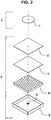
- Fig. 2 is an exploded view showing an analyzer and a polarizer of the apparatus of the present invention.
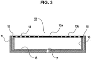
- Fig. 3 is a sectional view showing a surface illumination device and a holder of the apparatus of the present invention.
- Fig. 1 is a perspective view of a strain inspection apparatus according to the present invention.
- the strain inspection apparatus 1 is constituted by a rectangular shaped plate member 2, an analyzer 3 which is embedded in the plate member 2, two vertical supporting rods 4 which support the plate member 2, a main body 5 which supports the vertical rods 4, and a polarizer 6 which is housed in the main body 5.
- Fig. 2 is an exploded view which shows the analyzer 3 and the polarizer 6.
- the analyzer 3 is constituted by a first polarizing plate 7 of a disc-shape.
- the polarizer 6 is constituted by a second polarizing plate 8 which opposes to the first polarizing plate 7 with an object to be tested (not shown) positioned therebetween, a diffusion plate 9 displaced under the second polarizing plate 8, a surface illumination device 10 arranged under the diffusion plate 9, a holder 11 which houses therein the surface illumination device 10, and an LED diode 12 arranged at the central portion of the bottom surface of the holder 11.
- Fig. 3 is a sectional view which illustrates a state in which the surface illumination device 10 is accommodated in the holder 11 of the strain inspection apparatus of the invention.
- the surface illustration device 10 has a casing 18 which is housed in the holder 11.
- the casing 18 comprises reflection sidewall surfaces 16 at its sidewalls, and a reflection bottom surface 15 at its bottom. At the center of the reflection bottom surface 15, there is provided an opening 17 for an LED 12.
- the reflection sidewall surfaces 16 and the reflection bottom surface 15 allow reflection and diffusing-reflection of light.
- the upper opening of the housing 18 is covered by a light emission-side reflection plate 13 which allows penetration, reflection and diffusing-reflection of light.
- the light emission-side reflection plate 13 is constituted by a central reflection part 13a having a predetermined area right above the opening 17 for the LED 12 and an outer reflection part 13b which surrounds the central reflection part 13a.
- the outside reflection part 13b is formed by the reflection material which has a predetermined reflectance and allows penetration, reflection and diffusing reflection of a part of light, while the central reflection part 13a is formed by the reflection material of light permeability which has higher reflectance than that of the outside reflection part 13b.
- the reflection bottom surface 15, the reflection sidewall surfaces 16 and the light emission-side reflection plate 13 are made of materials having low light absorption characteristics.
- the light emitted from the LED 12 is multi-reflected by the reflection bottom surface 15 at the bottom and the reflection sidewall surfaces 16 at the sides of the casing 18 without being absorbed by the respective reflection members.
- the above construction makes it possible to utilize substantially full amount of light emitted from the LED 12.
- the surface illumination device 10 some amount of the light emitted from the LED 12 having strong directivity penetrates the central reflection part 13a and the remaining thereof is reflected by the same central reflection part 13a.
- the light reflected by the central reflection part 13a penetrates the outer reflection part 13b after it is multi-reflected by the reflection bottom surface 15, the reflection sidewall surfaces 16 and the outer reflection part 13b.
- the amount of light penetration at the central portion where intensity of light is high is limited while the amount of light penetration at the portion other than the central portion increases progressively so that the evenness of illumination light can be achieved.
- the light emitted from the LED 12 is multi-reflected inside the casing 18, the vertical dimension of the device can be made small as compared to the conventional one, thereby making it possible to construct the overall device compact.
- the outer reflection part 13b is provided with a plurality of fine or small holes 14 such as circle-, oblique- or square-holes in such a manner that the dimension of openings becomes progressively large in the outward direction as shown in Fig. 3 .
- the amount of penetration light can be increased in accordance with increase in distance from the central portion to the outer portion, whereby the evenness of illumination light can be attained.
- Opening areas of the small holes 14 in the outer reflection part 13b may be same.
- the number of holes 14 arranged at the outer periphery of the outer reflection part 13b is larger than that arranged near the central reflection part 13a.
- the materials forming the respective components such as the central reflection part 13a are not limitative and can be selected according to the desire.
- an optical reflective plate well known in the art can be used, or alternatively, a plate on which reflection material is sputtered may be used.
- An optical diffusion plate such as a frosted glass may be used as the light emission-side reflection plate 13.
- the device disclosed in Japanese Patent No. 4280283 namely, Product Name "Flatter” (commercially available from Opto-Design Inc., in Tokyo Japan) can be used.
- the number of LEDs is not limited to only one and a plurality of LEDs may be assembled as a unit so as to obtain a larger amount of light.
- the LED may consist of red, green and blue light emitting elements of three primary colors.
- the LED may be constituted by surface mounting type diode.
- the LED is positioned at the bottom center of the holder 11 in the above explained embodiment, the LED or LEDs may be arranged at any given position at the bottom surface of the holder 11 according to the design choice as far as desired even illumination of light can be obtained by such modification of reflectance of the respective elements in the illumination device.
Landscapes
- Physics & Mathematics (AREA)
- General Physics & Mathematics (AREA)
- Length Measuring Devices By Optical Means (AREA)
- Investigating Or Analysing Materials By Optical Means (AREA)
Applications Claiming Priority (1)
| Application Number | Priority Date | Filing Date | Title |
|---|---|---|---|
| JP2011004523U JP3171325U (ja) | 2011-08-02 | 2011-08-02 | 歪検査器 |
Publications (2)
| Publication Number | Publication Date |
|---|---|
| EP2554963A2 true EP2554963A2 (fr) | 2013-02-06 |
| EP2554963A3 EP2554963A3 (fr) | 2015-01-21 |
Family
ID=46799335
Family Applications (1)
| Application Number | Title | Priority Date | Filing Date |
|---|---|---|---|
| EP12000772.9A Withdrawn EP2554963A3 (fr) | 2011-08-02 | 2012-02-06 | Appareil d'inspection de tension dans les matériaux transparents |
Country Status (3)
| Country | Link |
|---|---|
| EP (1) | EP2554963A3 (fr) |
| JP (1) | JP3171325U (fr) |
| CN (1) | CN202304762U (fr) |
Cited By (1)
| Publication number | Priority date | Publication date | Assignee | Title |
|---|---|---|---|---|
| EP2905577A1 (fr) * | 2014-02-07 | 2015-08-12 | Luceo Co., Ltd. | Appareil d'inspection de contrainte |
Families Citing this family (6)
| Publication number | Priority date | Publication date | Assignee | Title |
|---|---|---|---|---|
| JP5578329B2 (ja) * | 2011-12-13 | 2014-08-27 | スミックス株式会社 | ライン光源 |
| JP5966704B2 (ja) * | 2012-07-11 | 2016-08-10 | 株式会社島津製作所 | 基板検査装置および基板検査装置用透過照明装置 |
| JP6839439B2 (ja) * | 2016-12-01 | 2021-03-10 | 国立大学法人山口大学 | 試料観察装置 |
| JP7312448B2 (ja) * | 2019-05-17 | 2023-07-21 | シンクロア株式会社 | 目視支援装置 |
| CN110243509A (zh) * | 2019-05-30 | 2019-09-17 | 开平市盈光机电科技有限公司 | 一种新型透明复合材料的应力检测工艺 |
| CN114383760B (zh) * | 2021-12-30 | 2023-04-14 | 厦门大学 | 一种力学参数的测量装置和测量方法 |
Citations (1)
| Publication number | Priority date | Publication date | Assignee | Title |
|---|---|---|---|---|
| JP2008027886A (ja) | 2006-01-27 | 2008-02-07 | Opt Design:Kk | 面照明光源装置及びこれを用いた面照明装置 |
Family Cites Families (2)
| Publication number | Priority date | Publication date | Assignee | Title |
|---|---|---|---|---|
| DE2403033A1 (de) * | 1974-01-23 | 1975-07-24 | Elmed Ges Fuer Elektrophysik U | Vorrichtung zur spannungsoptischen untersuchung |
| US7061612B2 (en) * | 2004-09-28 | 2006-06-13 | Osram Sylvania Inc. | LED Polarimeter |
-
2011
- 2011-08-02 JP JP2011004523U patent/JP3171325U/ja not_active Expired - Lifetime
- 2011-08-29 CN CN 201120317232 patent/CN202304762U/zh not_active Expired - Lifetime
-
2012
- 2012-02-06 EP EP12000772.9A patent/EP2554963A3/fr not_active Withdrawn
Patent Citations (2)
| Publication number | Priority date | Publication date | Assignee | Title |
|---|---|---|---|---|
| JP2008027886A (ja) | 2006-01-27 | 2008-02-07 | Opt Design:Kk | 面照明光源装置及びこれを用いた面照明装置 |
| JP4280283B2 (ja) | 2006-01-27 | 2009-06-17 | 株式会社オプトデザイン | 面照明光源装置及びこれを用いた面照明装置 |
Cited By (1)
| Publication number | Priority date | Publication date | Assignee | Title |
|---|---|---|---|---|
| EP2905577A1 (fr) * | 2014-02-07 | 2015-08-12 | Luceo Co., Ltd. | Appareil d'inspection de contrainte |
Also Published As
| Publication number | Publication date |
|---|---|
| EP2554963A3 (fr) | 2015-01-21 |
| JP3171325U (ja) | 2011-10-27 |
| CN202304762U (zh) | 2012-07-04 |
Similar Documents
| Publication | Publication Date | Title |
|---|---|---|
| EP2554963A2 (fr) | Appareil d'inspection de tension dans les matériaux transparents | |
| US7806540B2 (en) | Illumination device | |
| KR200473035Y1 (ko) | 렌즈 검사 시스템 | |
| JP5606981B2 (ja) | 光量安定化光源装置 | |
| CN102829959B (zh) | 一种导光板透过率光谱的测试装置及方法 | |
| CN106644989B (zh) | 一种吸光度的检测系统 | |
| JP2017211378A (ja) | 試験試料である平坦品の表面外観を検査する検査装置および検査方法 | |
| TW201333499A (zh) | 待測發光元件之光檢測裝置及其方法 | |
| CN102141218B (zh) | 光源装置 | |
| CN105277339B (zh) | 量测系统 | |
| CN112334756A (zh) | 用于检查微量滴定板的腔体中的样品的透射装置和借助于透射检查微量滴定板的腔体中的样品的方法 | |
| CN116067622B (zh) | 一种用于平面光导氛围灯光色质量测试的部件 | |
| JP2017187425A (ja) | 欠陥検査装置、欠陥検査方法、及び、バルーンカテーテルの製造方法 | |
| JP6094186B2 (ja) | 穀物外観検査キット及び穀物外観検査方法 | |
| CN104102008A (zh) | 能增加收光量及角度的收光装置 | |
| KR101119884B1 (ko) | 알지비 엘이디를 이용한 광섬유 조명의 검사 장치 | |
| KR100978487B1 (ko) | 기판검사용 조명장치 | |
| KR200419687Y1 (ko) | 평판표시장치의 결함 검사장치 | |
| JP4517574B2 (ja) | カラーフィルタ評価方法 | |
| KR102882989B1 (ko) | 원편광판 검사 장치 및 원편광판 검사 방법 | |
| JP2006202665A (ja) | 光源装置 | |
| JP5518546B2 (ja) | 基準光源装置 | |
| JP2016194473A (ja) | パターン製品の検査装置および方法 | |
| JP2008170342A (ja) | 光学性能測定装置及び光学性能測定方法 | |
| KR100923253B1 (ko) | 조명 장치 및 이를 포함하는 검사 장치 |
Legal Events
| Date | Code | Title | Description |
|---|---|---|---|
| PUAI | Public reference made under article 153(3) epc to a published international application that has entered the european phase |
Free format text: ORIGINAL CODE: 0009012 |
|
| AK | Designated contracting states |
Kind code of ref document: A2 Designated state(s): AL AT BE BG CH CY CZ DE DK EE ES FI FR GB GR HR HU IE IS IT LI LT LU LV MC MK MT NL NO PL PT RO RS SE SI SK SM TR |
|
| AX | Request for extension of the european patent |
Extension state: BA ME |
|
| PUAL | Search report despatched |
Free format text: ORIGINAL CODE: 0009013 |
|
| STAA | Information on the status of an ep patent application or granted ep patent |
Free format text: STATUS: THE APPLICATION IS DEEMED TO BE WITHDRAWN |
|
| AK | Designated contracting states |
Kind code of ref document: A3 Designated state(s): AL AT BE BG CH CY CZ DE DK EE ES FI FR GB GR HR HU IE IS IT LI LT LU LV MC MK MT NL NO PL PT RO RS SE SI SK SM TR |
|
| AX | Request for extension of the european patent |
Extension state: BA ME |
|
| RIC1 | Information provided on ipc code assigned before grant |
Ipc: G01L 1/24 20060101AFI20141212BHEP Ipc: G01N 21/958 20060101ALI20141212BHEP |
|
| 18D | Application deemed to be withdrawn |
Effective date: 20140902 |