EP2555007A1 - Procédé d'estimation de l'état de charge, dispositif d'estimation de l'état de charge et système électrique à accumulateur secondaire - Google Patents
Procédé d'estimation de l'état de charge, dispositif d'estimation de l'état de charge et système électrique à accumulateur secondaire Download PDFInfo
- Publication number
- EP2555007A1 EP2555007A1 EP11762404A EP11762404A EP2555007A1 EP 2555007 A1 EP2555007 A1 EP 2555007A1 EP 11762404 A EP11762404 A EP 11762404A EP 11762404 A EP11762404 A EP 11762404A EP 2555007 A1 EP2555007 A1 EP 2555007A1
- Authority
- EP
- European Patent Office
- Prior art keywords
- voltage measurement
- voltage
- measurement value
- charge
- state
- Prior art date
- Legal status (The legal status is an assumption and is not a legal conclusion. Google has not performed a legal analysis and makes no representation as to the accuracy of the status listed.)
- Granted
Links
Images




Classifications
-
- G—PHYSICS
- G01—MEASURING; TESTING
- G01R—MEASURING ELECTRIC VARIABLES; MEASURING MAGNETIC VARIABLES
- G01R31/00—Arrangements for testing electric properties; Arrangements for locating electric faults; Arrangements for electrical testing characterised by what is being tested not provided for elsewhere
- G01R31/36—Arrangements for testing, measuring or monitoring the electrical condition of accumulators or electric batteries, e.g. capacity or state of charge [SoC]
- G01R31/382—Arrangements for monitoring battery or accumulator variables, e.g. SoC
- G01R31/3835—Arrangements for monitoring battery or accumulator variables, e.g. SoC involving only voltage measurements
Definitions
- the present invention relates to the technical field of a state-of-charge estimation method and a state-of-charge estimation device for estimating the state of charge of a secondary battery to supply electric power to load.
- the current state of charge of a secondary battery such as a lead acid storage battery mounted on a car etc. is required to be accurately known.
- a secondary battery in general, since correlation exists between the state of charge and the open-circuit voltage (OCV) in a stable condition, the state of charge may be estimated by calculating the open-circuit voltage.
- OCV open-circuit voltage
- the open-circuit voltage of the secondary battery must be measured when charging or discharging is not being performed, and it takes a long time for the open-circuit voltage to be stabilized after charging or discharging is finished. Therefore, various methods for calculating convergence value of the open-circuit voltage have been proposed using the function (voltage characteristic formula) for approximating the time characteristics of the open-circuit voltage (for example, Patent Documents 1 to 3).
- the voltage characteristic formula of the open-circuit voltage has an adjustment parameter, and this adjustment parameter is determined by using the measured value of the open-circuit voltage obtained by measuring for a short period of time. And the convergence value of the open-circuit voltage is calculated using the voltage characteristic formula applied with the determined adjustment parameter.
- the convergence value of the open-circuit voltage of the secondary battery is calculated with the above-described conventional method, its precision depends on the precision of the voltage characteristic formula.
- a polynomial function, a logarithmic function, etc. are used as a voltage characteristic formula; however, since approximating the time characteristics of the open-circuit voltage of the secondary battery with high precision using these functions is difficult, the error of the convergence value of the open-circuit voltage is large.
- a quartic or more exponential attenuation function is used for approximate calculation of the open-circuit voltage of the secondary battery to be able to approximate the open-circuit voltage with high precision and to estimate the state of charge with high precision.
- a complicated nonlinear function such as a quartic or more exponential attenuation function is used for approximate calculation of the open-circuit voltage of the secondary battery
- the optimum solution of the least-square method must be obtained by solving sequential calculation such as the Gauss-Newton method or the Levenberg-Marquardt method or by performing filtering calculation such as Kalman filter calculation.
- the Patent Document 4 proposes a method for quickly and stably determining the convergence value of an adjustment parameter.
- the initial value of the adjustment parameter is uniquely determined by using only the initial voltage measurement value during the data acquisition period and the voltage measurement value immediately before completion. Therefore, an unsuitable value may be set as an initial value, in which case the optimal calculation of the adjustment parameter may not converge. That is to say, when change of the open-circuit voltage after charge/discharge of the secondary battery finishes is within the range of the voltage profile (gradually lowering or rising) assumed in advance, the optimization of the adjustment parameter is possible; however, since there are various charge/discharge histories in real vehicles, the voltage profile may be outside the assumed range. As an example, as shown in FIG.
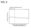
- the change of the voltage measurement value is reversed in the middle of a voltage measurement period.
- the initial value of the adjustment parameter is determined from the initial voltage measurement value during the data acquisition period and the voltage measurement value immediately before completion even with such a voltage profile, the optimization of the adjustment parameter sometimes did not converge.
- the present invention is devised to solve these problems, and has an object to provide a state-of-charge estimation method, a state-of-charge estimation device, and a secondary-battery power system that may quickly and stably determine the convergence value of the adjustment parameter of the voltage characteristic formula that may approximate change over time of the open-circuit voltage of the secondary battery with high precision by appropriately setting the initial value of the adjustment parameter and estimate the state of charge.
- the first aspect of the state-of-charge estimation method is a state-of-charge estimation method, wherein change over time of an open-circuit voltage (OCV) of a secondary battery after completion of charge/discharge is approximated with a voltage characteristic formula having an adjustment parameter, and the open-circuit voltage in a stable condition of the secondary battery is calculated from the voltage characteristic formula to estimate the state of charge of the secondary battery, and wherein the method obtains m (m is a natural number) measured values (hereinafter referred to as a voltage measurement value) of the open-circuit voltage of the secondary battery in a given cycle during a given data acquisition period after completion of charge/discharge of the secondary battery, selects the voltage measurement value at given selection timing from the m voltage measurement values to use as a selected voltage measurement value, calculates the initial value of the adjustment parameter based on the selected voltage measurement value and the selection timing, calculates the convergence value by gradually correcting the adjustment parameter from the initial value so that the error between the open-circuit voltage calculated with the voltage characteristic
- OCV
- the cycle to obtain the voltage measurement value is ⁇ t, and the C is a real number set in advance
- V0c are calculated with:
- the cycle to obtain the voltage measurement value is ⁇ t
- the C is a real number set in advance
- the cycle to obtain the voltage measurement value is ⁇ t
- the C is a real number set in advance
- the open-circuit voltage when the secondary battery is in a stable condition is calculated by substituting a given time defined in advance to the voltage characteristic formula using the convergence value for the adjustment parameter.
- the first aspect of the state-of-charge estimation device provides a state-of-charge estimation device for estimating a state of charge of a secondary battery, including: a voltage sensor for measuring a voltage of the secondary battery; a control part for performing and controlling calculation for estimating the state of charge using a voltage characteristic formula having an adjustment parameter; a storage part for storing a voltage measurement value measured with the voltage sensor and data used for the calculation with the control part, wherein the control part obtains m (m is a natural number) measured values (hereinafter referred to as a voltage measurement value) of the open-circuit voltage of the secondary battery in a given cycle during a given data acquisition period after completion of charge/discharge of the secondary battery, selects a voltage measurement value at given selection timing from the m voltage measurement values to use as a selected voltage measurement value, calculates the initial value of the adjustment parameter based on the selected voltage measurement value and the selection timing, calculates the convergence value by gradually correcting the adjustment parameter from the initial value so that the error between the open-
- the first aspect of the secondary-battery power system according to the present invention includes a secondary battery; a charging circuit for charging the secondary battery; and the state-of-charge estimation device according to claim 9 or 10 for estimating the state of charge of the secondary battery.
- a state-of-charge estimation method may quickly and stably determine the convergence value of the adjustment parameter of the voltage characteristic formula that may approximate change over time of the open-circuit voltage of the secondary battery with high precision by appropriately setting the initial value of the adjustment parameter and estimate the state of charge.
- a state-of-charge estimation method, a state-of-charge estimation device, and the structure of a secondary-battery power system according to preferred embodiments of the present invention are illustrated in detail with reference to the drawings. Components with the same function are indicated by the same reference numerals for the purpose of simplifying the drawings and description.
- the present invention is applied to a secondary battery mounted on a vehicle, such as a car, for explanation, but is not limited thereto.
- FIG. 2 is a block diagram showing the outline structure of a state-of-charge estimation device 101 and a secondary-battery power system 100 according to this embodiment.
- the secondary-battery power system 100 may be configured with a secondary battery 110 and the state-of-charge estimation device 101 for estimating the state of charge of the secondary battery 110.
- the state-of-charge estimation device 101 includes a voltage sensor 120 for measuring the voltage of the secondary battery 110; a control part 130 for inputting a voltage measurement value from the voltage sensor 120 and estimating the state of charge of the secondary battery 110; and a storage part 140 for storing data etc. that are used for calculation performed by the control part 130.
- the voltage sensor 120 is used for measuring the open-circuit voltage of the secondary battery 110 in a given cycle after completion of charge/discharge.
- the control part 130 obtains the open-circuit voltage from the voltage sensor 120 in a given cycle and saves it in the storage part 140 during the data acquisition period after completion of charge/discharge.
- the secondary-battery power system 100 may be configured so that the control part 130 also controls charge of the secondary battery 110 based on the state of charge estimated by the control part 130.
- FIG. 2 shows an example in which the secondary-battery power system 100 is also provided with a charging circuit 150, and controls the charging circuit 150 based on the state of charge estimated by the control part 130 to charge the secondary battery 110.
- the secondary-battery power system 100 configured as described above is connected with a load 10, such as a motor, and electric power is supplied to the load 10 from the secondary battery 110.
- a load 10 such as a motor
- electric power is supplied to the load 10 from the secondary battery 110.
- a lead acid storage battery is used as the secondary battery 110, for example.
- the control part 130 configured with a CPU etc. for performing data processing performs data processing for estimating the state of charge as described below at given timing.
- the storage part 140 connected to the control part 130 includes a ROM for storing various programs, such as a control program, in advance, and a RAM for storing various data used for processing the control part 130, etc.
- the state-of-charge estimation method according to this embodiment is used for estimating the state of charge of the secondary battery 110 in the control part 130 of the state-of-charge estimation device 101.
- the state of charge of the secondary battery has a strong correlation with the open-circuit voltage when the secondary battery is stable; therefore, if the open-circuit voltage in a stable condition (hereinafter referred to as a stable open-circuit voltage) is calculated, the state of charge of the secondary battery may be estimated.
- FIG. 3 An example of change over time of the open-circuit voltage of the secondary battery 110 after charge/discharge finishes is shown in FIG. 3 .
- the horizontal axis indicates the elapsed time t after completion of charge/discharge
- the vertical axis indicates the open-circuit voltage of the secondary battery 110.
- the open-circuit voltage indicated by the numeral 11 is lowered in monotone after completion of charge/discharge, the stable open-circuit voltage is not reached even after 30 minutes. Therefore, charge/discharge must be stopped for longer period of time to wait for the open-circuit voltage to be stabilized to measure the stable open-circuit voltage.
- the open-circuit voltages indicated by the numerals 12 to 15 tends to temporarily increase after completion of charge/discharge, gradually decrease after reaching the peak value, and the stable open-circuit voltage is not reached even after 30 minutes. Changes of the open-circuit voltages after charge/discharge stops vary as shown in FIG. 3 based on the states of charge/discharge in the past. Especially, there is a tendency for the open-circuit voltage to temporarily increase immediately after completion of charge/discharge when there is a large discharge from the secondary battery before completion of charge/discharge as shown by the numerals 12 to 15 that indicate change of the open-circuit voltage shown in FIG. 3 . In this case, the peak point of the open-circuit voltage changes based on the state of charge/discharge.
- a voltage characteristic formula is used that may approximate change over time of the open-circuit voltage of the secondary battery 110 after completion of charge/discharge with high precision.
- This voltage characteristic formula is optimally approximated using the voltage measurement value obtained during the given data acquisition period after completion of charge/dischargeso that the stable open-circuit voltage may be estimated with high precision without waiting for the secondary battery 110 to be stabilized.
- An example of the data acquisition period is shown by the numeral 20 in FIG. 3 .
- a data acquisition period TD is sufficiently short compared with the time taken to stabilize the open-circuit voltage after completion of charge/discharge, and may be approximately 30 minutes, for example.
- the following approximate expression including a quartic or more exponential attenuation function should be used as a voltage characteristic formula.
- a quadratic or cubic exponential attenuation function may be used as a voltage characteristic formula.
- V t A 1 x exp B 1 x t ) + A 2 x exp B 2 x t + ... + A n x exp B n x t + Vc
- n an integer not less than 4 showing the order of the exponential attenuation function of the formula (1)
- the t is the elapsed time after completion of charge/discharge
- ⁇ A i ⁇ (i 1 to n)
- ⁇ B i ⁇ (i 1 to n)
- Vc are the adjustment parameters (fitting parameter).
- discharge basically does not completely stop even in the idle state, and very small amount of current, i.e., the dark current, continues to flow. Therefore, the open-circuit voltage in a strict sense can not be measured, and the voltage with the dark current flowing is considered to be an open-circuit voltage.
- the voltage characteristic formula (1) having a quartic or more exponential attenuation function need to be able to approximate change of the open-circuit voltage of the secondary battery 110 with high precision.
- the measured value of the open-circuit voltage of the secondary battery 110 obtained during the given data acquisition period after completion of charge/discharge is used to optimally adjust the adjustment parameter of the formula (1).
- each of the initial values A0 1 to A0 n of the adjustment parameters A 1 to An is calculated with the following formula:
- k b 2
- Each of the initial values B0 1 to B0 n of the adjustment parameters B 1 to B n is calculated with the following formula.
- B ⁇ 0 - 1 / b 1 - 1 x ⁇ t x C
- B ⁇ 0 2 - 1 / b 2 - 1 x ⁇ t x C
- B ⁇ 0 n - 1 - 1 / b n - 1 - 1 x ⁇ t x C
- B ⁇ 0 n - 1 / m - 1 x ⁇ t x C
- the C is a real number set in advance.
- V ⁇ 0 ⁇ c VM m
- V t A 1 x exp B 1 x t ) + A 2 x exp B 2 x t + A 3 x exp B 3 x t + A 4 x exp B 4 x t + Vc
- the formula shown above indicates that the gap between the selection timing of the selected voltage measurement value is short at the beginning of the data acquisition period TD, and becomes gradually longer.
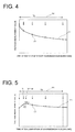
- FIG. 4 is a schematic diagram showing change of the open-circuit voltage of the secondary battery 110 for illustrating the selection timing of the selected voltage measurement value.
- the data acquisition period TD shown by the numeral 20 is magnified.
- the numeral 21 denotes the open-circuit voltage
- the circles with the numeral 22 denote the selected voltage measurement values used for calculating the initial value of the adjustment parameter.
- the gap between the selection timing of the selected voltage measurement value 22 becomes gradually longer from the beginning to the end of the data acquisition period TD.
- the selection timing of the selected voltage measurement value 22 is preferably set to correspond to the amount of change (rate of change) of the open-circuit voltage 21. That is to say, as shown in FIG. 4 , the open-circuit voltage 21 shows a large change at the beginning of the data acquisition period TD, and shows a smaller change as it approaches the end. Therefore, the selection timing of the selected voltage measurement value 22 is provided with small gaps at the beginning of the data acquisition period TD with a large change of the open-circuit voltage 21, and the gaps of the selection timing of the selected voltage measurement value 22 should preferably be longer as the change of the open-circuit voltage 21 becomes smaller.
- the formula (8) indicates that the gaps of the selection timing of the selected voltage measurement value 22 are set as described above.
- the order of the voltage characteristic formula may be quadratic or cubic as described above.
- the convergence value of the adjustment parameter calculated as described above is used for the voltage characteristic formula (1) (formula (6) when the order n is 4) to calculate the stable open-circuit voltage of the secondary battery 110 therewith.
- the stable open-circuit voltage is given with the value Vc when the elapsed time t is infinite in the formula (1).
- the stable open-circuit voltage may be calculated by substituting the given time defined in advance required for the battery voltage to be stable into the t of the formula (1). Once the stable open-circuit voltage is calculated, the state of charge corresponding to the calculated stable open-circuit voltage may be estimated from the relation between the stable open-circuit voltage and the state of charge prepared in advance.
- Data processing shown in FIG. 1 is a process mainly performed by the control part 130 based on the control program held in the storage part 140, and starts immediately after completion of charge/discharge of the secondary battery 110 in the secondary-battery power system 100, or at given timing after completion.
- the initial value V0c of the adjustment parameter Vc is calculated from the formula (5).
- the above-described error variance is given with the following formula.
- the tj is the elapsed time after completion of charge/discharge corresponding to VM j .
- S ⁇ V t j - VM j 2
- the optimized adjustment parameter Vc is used to estimate the state of charge of the secondary battery 110.
- the stable open-circuit voltage is calculated using the voltage characteristic formula (1), the exponential attenuation term is converged to 0 as the t becomes larger in the formula (1); therefore, the stable open-circuit voltage is equal to the constant term Vc of the formula (1).
- the open-circuit voltage in a stable condition may be immediately obtained from the constant term Vc of the formula (1).
- the stable open-circuit voltage may be calculated by substituting the given time defined in advance required for the battery voltage to be stable into the voltage characteristic formula (1) using the optimized adjustment parameter.
- the selection timing of the selected voltage measurement value is provided with small gaps at the beginning of the data acquisition period with large change of the open-circuit voltage, and the gaps of the selection timing of the selected voltage measurement value becomes longer as change of the open-circuit voltage becomes smaller. Thereby, the convergence value of the adjustment parameter may be determined quickly and stably.
- FIG. 5 is a diagram for illustrating how to calculate the initial value of the adjustment parameter of the voltage characteristic formula (1) in the state-of-charge estimation method according to this embodiment, and schematically shows change of the open-circuit voltage of a secondary battery 110.
- the formula (1) is optimized in the same manner as the first embodiment and the stable open-circuit voltage is calculated by using the optimized formula (1) below. Moreover, the state of charge of the secondary battery 110 is estimated from the calculated stable open-circuit voltage.
- the flow chart of the process of the state-of-charge estimation method according to this embodiment is shown in FIG. 6 . Hereinafter, difference from FIG. 1 showing the flow of the processes of the state-of-charge estimation method according to the first embodiment is described.
- Steps S21 to S24 are added in the flow of the processes of the state-of-charge estimation method according to this embodiment.
- the process proceeds to step S22, while when it has no peak, the process proceeds to step S13.
- steps S14 to S19 are successively processed to estimate the state of charge of the secondary battery 110 in the same manner as the first embodiment.
- each exponential attenuation item of the voltage characteristic formula (1) may be divided for optimization depending on when the voltage measurement value VM j is increasing or decreasing.
- the convergence value of the adjustment parameter may be quickly and stably determined.
- FIG. 7 is a diagram for illustrating how to calculate the initial value of the adjustment parameter of the voltage characteristic formula (1) in the state-of-charge estimation method according to this embodiment, and schematically shows change of the open-circuit voltage of a secondary battery 110.
- the formula (1) is optimized and used to calculate the stable open-circuit voltage. Moreover, the state of charge of the secondary battery 110 is estimated from the calculated stable open-circuit voltage.
- the flow of the process of the state-of-charge estimation method according to this embodiment is shown in FIG. 8 . Hereinafter, difference from FIG. 1 showing the flow of the process of the state-of-charge estimation method according to the first embodiment is described.
- Steps S31 to S34 are added in the flow of the processes of the state-of-charge estimation method according to this embodiment.
- the process proceeds to step S32, while when it has no peak, the process proceeds to step S13.
- the integer string ⁇ bc i ⁇ is expressed in the following formula.
- the above-described integer string ⁇ bc i ⁇ is distributed between the integer jp and the m, and never exceeds the m; therefore, (n - 1) voltage measurement values ((n+1) when including the jp and them) required for calculating the initial value maybe selected.
- the voltage characteristic formula (formula 1) including four terms of exponential attenuation function is described as an example; however, not limited to four terms, and more terms of the exponential attenuation function may be included.
- the number to obtain the voltage measurement values, etc. and sampling period etc. after completion of charge/discharge of the secondary battery may be suitably changed depending on the characteristics, the degree of degradation, etc. of the secondary battery.
- the initial value of the adjustment parameter of the voltage characteristic formula that may approximate change over time of the open-circuit voltage of the secondary battery with high precision may be appropriately set.
- a state-of-charge estimation method, a state-of-charge estimation device, and a secondary-battery power system that may quickly and stably determine the convergence value of the adjustment parameter and estimate the state of charge. Calculation may be successively converged quickly (fewer repetition) for various voltage profiles. Thereby, computation is possible even with built-in software with limited computing capability, for example.
- the description in the embodiments only shows examples of the state-of-charge estimation method, the state-of-charge estimation device, and thesecondary-battery powersystem according to the present invention, and is not limited thereto. Detailed structure, detailed operation, etc. of the state-of-charge estimation method, the state-of-charge estimation device, and the secondary-battery power system according to the embodiments may be suitably changed without departing from the spirit of the present invention.
Landscapes
- Physics & Mathematics (AREA)
- General Physics & Mathematics (AREA)
- Secondary Cells (AREA)
- Tests Of Electric Status Of Batteries (AREA)
- Charge And Discharge Circuits For Batteries Or The Like (AREA)
Applications Claiming Priority (2)
| Application Number | Priority Date | Filing Date | Title |
|---|---|---|---|
| JP2010079617A JP5520657B2 (ja) | 2010-03-30 | 2010-03-30 | 充電率推定方法、充電率推定装置及び二次電池電源システム |
| PCT/JP2011/053683 WO2011122164A1 (fr) | 2010-03-30 | 2011-02-21 | Procédé d'estimation de l'état de charge, dispositif d'estimation de l'état de charge et système électrique à accumulateur secondaire |
Publications (3)
| Publication Number | Publication Date |
|---|---|
| EP2555007A1 true EP2555007A1 (fr) | 2013-02-06 |
| EP2555007A4 EP2555007A4 (fr) | 2017-07-26 |
| EP2555007B1 EP2555007B1 (fr) | 2019-01-09 |
Family
ID=44711897
Family Applications (1)
| Application Number | Title | Priority Date | Filing Date |
|---|---|---|---|
| EP11762404.9A Active EP2555007B1 (fr) | 2010-03-30 | 2011-02-21 | Procédés d'estimation de l'état de charge |
Country Status (5)
| Country | Link |
|---|---|
| US (1) | US8903667B2 (fr) |
| EP (1) | EP2555007B1 (fr) |
| JP (1) | JP5520657B2 (fr) |
| CN (1) | CN102803980B (fr) |
| WO (1) | WO2011122164A1 (fr) |
Cited By (1)
| Publication number | Priority date | Publication date | Assignee | Title |
|---|---|---|---|---|
| EP2860539A4 (fr) * | 2012-06-05 | 2016-01-27 | Toyota Jidoshokki Kk | Procédé d'estimation d'un état de charge et dispositif d'estimation d'un état de charge |
Families Citing this family (20)
| Publication number | Priority date | Publication date | Assignee | Title |
|---|---|---|---|---|
| JP5842421B2 (ja) * | 2010-07-20 | 2016-01-13 | 日産自動車株式会社 | 電池状態推定装置 |
| JPWO2013054414A1 (ja) * | 2011-10-13 | 2015-03-30 | トヨタ自動車株式会社 | 二次電池の制御装置および制御方法 |
| WO2013054414A1 (fr) * | 2011-10-13 | 2013-04-18 | トヨタ自動車株式会社 | Dispositif et procédé de régulation d'une batterie rechargeable |
| US9091738B2 (en) * | 2012-10-10 | 2015-07-28 | GM Global Technology Operations LLC | Vehicle battery pack cell voltage determination |
| DE112013005699B4 (de) * | 2012-11-29 | 2023-03-23 | Mitsubishi Electric Corporation | Schätzvorrichtung für einen internen Zustand einer Batterie |
| JP6155774B2 (ja) | 2013-04-03 | 2017-07-05 | 株式会社Gsユアサ | 状態推定装置及び状態推定方法 |
| JP5958424B2 (ja) * | 2013-06-11 | 2016-08-02 | 株式会社豊田自動織機 | 2次電池の充電開始制御方法及び充電装置 |
| CN104714181B (zh) * | 2013-12-11 | 2017-10-27 | 广州汽车集团股份有限公司 | 一种获取电压与电池荷电状态关系的方法和系统 |
| JP6555773B2 (ja) * | 2014-11-18 | 2019-08-07 | 学校法人立命館 | 蓄電残量推定装置、蓄電池の蓄電残量を推定する方法、及びコンピュータプログラム |
| CN111545143A (zh) | 2015-04-09 | 2020-08-18 | 沙特阿拉伯石油公司 | 用于提高烃采收的胶囊型纳米组合物及其制备方法 |
| KR102805831B1 (ko) | 2017-01-17 | 2025-05-12 | 삼성전자주식회사 | 배터리 상태 추정 방법 및 장치 |
| CN109066874A (zh) * | 2018-08-30 | 2018-12-21 | 北京小米移动软件有限公司 | 快速充电方法及装置、电子设备、计算机可读存储介质 |
| CN113508488B (zh) * | 2019-02-28 | 2024-03-29 | 古河电气工业株式会社 | 可充电电池状态检测装置和可充电电池状态检测方法 |
| KR102521576B1 (ko) * | 2019-03-18 | 2023-04-12 | 주식회사 엘지에너지솔루션 | 배터리 관리 장치 |
| CN112989690B (zh) * | 2021-02-07 | 2024-05-24 | 南京航空航天大学 | 一种混合动力汽车锂电池多时间尺度荷电状态估计方法 |
| CN114325425A (zh) * | 2022-01-07 | 2022-04-12 | 迈科新能源(深圳)有限公司 | 一种基于磷酸铁锂电池用检测方法 |
| CN114545260B (zh) * | 2022-02-25 | 2022-10-18 | 威胜电气有限公司 | 一种电池容量解耦的锂电池荷电状态估计方法 |
| KR102827611B1 (ko) * | 2022-03-03 | 2025-07-01 | 주식회사 민테크 | 배터리 상태 추정 방법 |
| JP7690422B2 (ja) * | 2022-03-28 | 2025-06-10 | 株式会社Aescジャパン | 電池管理装置、電池管理方法、およびプログラム |
| CN120405448B (zh) * | 2025-07-03 | 2025-11-04 | 杭州科工电子科技股份有限公司 | 一种锂电池的电池荷电状态预测方法、装置及介质 |
Family Cites Families (13)
| Publication number | Priority date | Publication date | Assignee | Title |
|---|---|---|---|---|
| JPH0798367A (ja) | 1993-09-28 | 1995-04-11 | Honda Motor Co Ltd | 電池の残容量推定方法 |
| JP3869676B2 (ja) | 2000-12-08 | 2007-01-17 | 矢崎総業株式会社 | 車両用バッテリの開回路電圧推定方法及び装置 |
| JP3747826B2 (ja) | 2001-09-05 | 2006-02-22 | 日産自動車株式会社 | 二次電池の充電率推定装置 |
| JP3714321B2 (ja) | 2002-11-25 | 2005-11-09 | 日産自動車株式会社 | 二次電池の充電率推定装置 |
| JP4015128B2 (ja) * | 2003-07-09 | 2007-11-28 | 古河電気工業株式会社 | 充電率推定方法、充電率推定装置、電池システム及び車両用電池システム |
| JP4830382B2 (ja) * | 2005-07-19 | 2011-12-07 | 日産自動車株式会社 | 二次電池の充電率推定装置 |
| JP4532416B2 (ja) * | 2006-01-12 | 2010-08-25 | 古河電気工業株式会社 | バッテリ放電能力判定方法、バッテリ放電能力判定装置、及び電源システム |
| JP4785056B2 (ja) * | 2006-10-13 | 2011-10-05 | 古河電気工業株式会社 | 充電率推定方法、充電率推定装置及び二次電池電源システム |
| JP4703593B2 (ja) * | 2007-03-23 | 2011-06-15 | 株式会社豊田中央研究所 | 二次電池の状態推定装置 |
| US7899631B2 (en) * | 2007-03-29 | 2011-03-01 | The Furukawa Electric Co., Ltd. | Method and device for estimating battery residual capacity, and battery power supply system |
| JP4865627B2 (ja) * | 2007-03-29 | 2012-02-01 | 古河電気工業株式会社 | バッテリ残存容量推定方法、バッテリ残存容量推定装置及びバッテリ電源システム |
| JP2010002227A (ja) * | 2008-06-18 | 2010-01-07 | Autonetworks Technologies Ltd | 開放電圧推定方法及び電源装置 |
| JP4649682B2 (ja) * | 2008-09-02 | 2011-03-16 | 株式会社豊田中央研究所 | 二次電池の状態推定装置 |
-
2010
- 2010-03-30 JP JP2010079617A patent/JP5520657B2/ja active Active
-
2011
- 2011-02-21 WO PCT/JP2011/053683 patent/WO2011122164A1/fr not_active Ceased
- 2011-02-21 EP EP11762404.9A patent/EP2555007B1/fr active Active
- 2011-02-21 CN CN201180014445.XA patent/CN102803980B/zh active Active
-
2012
- 2012-09-14 US US13/616,792 patent/US8903667B2/en active Active
Non-Patent Citations (1)
| Title |
|---|
| See references of WO2011122164A1 * |
Cited By (1)
| Publication number | Priority date | Publication date | Assignee | Title |
|---|---|---|---|---|
| EP2860539A4 (fr) * | 2012-06-05 | 2016-01-27 | Toyota Jidoshokki Kk | Procédé d'estimation d'un état de charge et dispositif d'estimation d'un état de charge |
Also Published As
| Publication number | Publication date |
|---|---|
| CN102803980A (zh) | 2012-11-28 |
| JP2011209237A (ja) | 2011-10-20 |
| JP5520657B2 (ja) | 2014-06-11 |
| EP2555007A4 (fr) | 2017-07-26 |
| CN102803980B (zh) | 2015-03-04 |
| EP2555007B1 (fr) | 2019-01-09 |
| WO2011122164A1 (fr) | 2011-10-06 |
| US20130013237A1 (en) | 2013-01-10 |
| US8903667B2 (en) | 2014-12-02 |
Similar Documents
| Publication | Publication Date | Title |
|---|---|---|
| EP2555007B1 (fr) | Procédés d'estimation de l'état de charge | |
| US6789026B2 (en) | Circuit and method for monitoring battery state of charge | |
| US9026389B2 (en) | State of charge computation system | |
| JP4015128B2 (ja) | 充電率推定方法、充電率推定装置、電池システム及び車両用電池システム | |
| US8004243B2 (en) | Battery capacity estimating method and apparatus | |
| JP5051661B2 (ja) | 二次電池のsoc値を推定する方法及び装置並びに劣化判定方法及び装置 | |
| EP1688754B1 (fr) | Appareil de gestion de batterie | |
| EP1975635B1 (fr) | Procédé et dispositif pour estimer la capacité résiduelle d'une batterie et système d'alimentation électrique par batterie | |
| EP1933159B1 (fr) | Procédé et dispositif pour déterminer l'état d'une batterie, et système d'alimentation électrique à batterie associé | |
| CN103852727B (zh) | 动力电池荷电状态在线估算方法和装置 | |
| EP4607215A1 (fr) | Procédé et appareil d'estimation d'état de charge de batterie, et dispositif de stockage d'énergie | |
| EP1906193B1 (fr) | Procédé et dispositif pour détecter l'état de charge de la batterie | |
| KR102557731B1 (ko) | 배터리의 순간 개방 회로 전압 프로파일의 추정 방법 및 장치 | |
| RU2690724C1 (ru) | Устройство оценки коэффициента емкости или способ оценки коэффициента емкости | |
| US11467217B2 (en) | Charge capacity calculation device and method for energy storage system | |
| JP2012185124A (ja) | 充電率推定装置、充電率推定方法、及びプログラム | |
| CN101447688A (zh) | 用于检测车内蓄电池的内部电气状态的装置和方法 | |
| JP4865627B2 (ja) | バッテリ残存容量推定方法、バッテリ残存容量推定装置及びバッテリ電源システム | |
| CN114460475B (zh) | 电池ocv确定方法及装置、电池soc的估算方法 | |
| JP4785056B2 (ja) | 充電率推定方法、充電率推定装置及び二次電池電源システム | |
| US12320856B2 (en) | Chargeable battery state detection apparatus and chargeable battery state detection method | |
| EP4685505A1 (fr) | Appareil et procédé d'estimation de la durée de vie d'une batterie | |
| JP2019070622A (ja) | 二次電池システム | |
| CN120254653A (zh) | 一种改进型动力电池soc估算方法 |
Legal Events
| Date | Code | Title | Description |
|---|---|---|---|
| PUAI | Public reference made under article 153(3) epc to a published international application that has entered the european phase |
Free format text: ORIGINAL CODE: 0009012 |
|
| 17P | Request for examination filed |
Effective date: 20120920 |
|
| AK | Designated contracting states |
Kind code of ref document: A1 Designated state(s): AL AT BE BG CH CY CZ DE DK EE ES FI FR GB GR HR HU IE IS IT LI LT LU LV MC MK MT NL NO PL PT RO RS SE SI SK SM TR |
|
| DAX | Request for extension of the european patent (deleted) | ||
| RA4 | Supplementary search report drawn up and despatched (corrected) |
Effective date: 20170623 |
|
| RIC1 | Information provided on ipc code assigned before grant |
Ipc: G01R 31/36 20060101AFI20170619BHEP |
|
| GRAP | Despatch of communication of intention to grant a patent |
Free format text: ORIGINAL CODE: EPIDOSNIGR1 |
|
| STAA | Information on the status of an ep patent application or granted ep patent |
Free format text: STATUS: GRANT OF PATENT IS INTENDED |
|
| INTG | Intention to grant announced |
Effective date: 20180503 |
|
| GRAS | Grant fee paid |
Free format text: ORIGINAL CODE: EPIDOSNIGR3 |
|
| GRAJ | Information related to disapproval of communication of intention to grant by the applicant or resumption of examination proceedings by the epo deleted |
Free format text: ORIGINAL CODE: EPIDOSDIGR1 |
|
| GRAL | Information related to payment of fee for publishing/printing deleted |
Free format text: ORIGINAL CODE: EPIDOSDIGR3 |
|
| STAA | Information on the status of an ep patent application or granted ep patent |
Free format text: STATUS: REQUEST FOR EXAMINATION WAS MADE |
|
| GRAJ | Information related to disapproval of communication of intention to grant by the applicant or resumption of examination proceedings by the epo deleted |
Free format text: ORIGINAL CODE: EPIDOSDIGR1 |
|
| STAA | Information on the status of an ep patent application or granted ep patent |
Free format text: STATUS: GRANT OF PATENT IS INTENDED |
|
| GRAP | Despatch of communication of intention to grant a patent |
Free format text: ORIGINAL CODE: EPIDOSNIGR1 |
|
| INTC | Intention to grant announced (deleted) | ||
| INTG | Intention to grant announced |
Effective date: 20181010 |
|
| GRAA | (expected) grant |
Free format text: ORIGINAL CODE: 0009210 |
|
| STAA | Information on the status of an ep patent application or granted ep patent |
Free format text: STATUS: THE PATENT HAS BEEN GRANTED |
|
| AK | Designated contracting states |
Kind code of ref document: B1 Designated state(s): AL AT BE BG CH CY CZ DE DK EE ES FI FR GB GR HR HU IE IS IT LI LT LU LV MC MK MT NL NO PL PT RO RS SE SI SK SM TR |
|
| REG | Reference to a national code |
Ref country code: GB Ref legal event code: FG4D |
|
| REG | Reference to a national code |
Ref country code: CH Ref legal event code: EP Ref country code: AT Ref legal event code: REF Ref document number: 1087991 Country of ref document: AT Kind code of ref document: T Effective date: 20190115 |
|
| REG | Reference to a national code |
Ref country code: IE Ref legal event code: FG4D |
|
| REG | Reference to a national code |
Ref country code: DE Ref legal event code: R096 Ref document number: 602011055575 Country of ref document: DE |
|
| REG | Reference to a national code |
Ref country code: NL Ref legal event code: MP Effective date: 20190109 |
|
| REG | Reference to a national code |
Ref country code: LT Ref legal event code: MG4D |
|
| PG25 | Lapsed in a contracting state [announced via postgrant information from national office to epo] |
Ref country code: NL Free format text: LAPSE BECAUSE OF FAILURE TO SUBMIT A TRANSLATION OF THE DESCRIPTION OR TO PAY THE FEE WITHIN THE PRESCRIBED TIME-LIMIT Effective date: 20190109 |
|
| REG | Reference to a national code |
Ref country code: AT Ref legal event code: MK05 Ref document number: 1087991 Country of ref document: AT Kind code of ref document: T Effective date: 20190109 |
|
| PG25 | Lapsed in a contracting state [announced via postgrant information from national office to epo] |
Ref country code: SE Free format text: LAPSE BECAUSE OF FAILURE TO SUBMIT A TRANSLATION OF THE DESCRIPTION OR TO PAY THE FEE WITHIN THE PRESCRIBED TIME-LIMIT Effective date: 20190109 Ref country code: ES Free format text: LAPSE BECAUSE OF FAILURE TO SUBMIT A TRANSLATION OF THE DESCRIPTION OR TO PAY THE FEE WITHIN THE PRESCRIBED TIME-LIMIT Effective date: 20190109 Ref country code: LT Free format text: LAPSE BECAUSE OF FAILURE TO SUBMIT A TRANSLATION OF THE DESCRIPTION OR TO PAY THE FEE WITHIN THE PRESCRIBED TIME-LIMIT Effective date: 20190109 Ref country code: PL Free format text: LAPSE BECAUSE OF FAILURE TO SUBMIT A TRANSLATION OF THE DESCRIPTION OR TO PAY THE FEE WITHIN THE PRESCRIBED TIME-LIMIT Effective date: 20190109 Ref country code: PT Free format text: LAPSE BECAUSE OF FAILURE TO SUBMIT A TRANSLATION OF THE DESCRIPTION OR TO PAY THE FEE WITHIN THE PRESCRIBED TIME-LIMIT Effective date: 20190509 Ref country code: NO Free format text: LAPSE BECAUSE OF FAILURE TO SUBMIT A TRANSLATION OF THE DESCRIPTION OR TO PAY THE FEE WITHIN THE PRESCRIBED TIME-LIMIT Effective date: 20190409 Ref country code: FI Free format text: LAPSE BECAUSE OF FAILURE TO SUBMIT A TRANSLATION OF THE DESCRIPTION OR TO PAY THE FEE WITHIN THE PRESCRIBED TIME-LIMIT Effective date: 20190109 |
|
| PG25 | Lapsed in a contracting state [announced via postgrant information from national office to epo] |
Ref country code: BG Free format text: LAPSE BECAUSE OF FAILURE TO SUBMIT A TRANSLATION OF THE DESCRIPTION OR TO PAY THE FEE WITHIN THE PRESCRIBED TIME-LIMIT Effective date: 20190409 Ref country code: GR Free format text: LAPSE BECAUSE OF FAILURE TO SUBMIT A TRANSLATION OF THE DESCRIPTION OR TO PAY THE FEE WITHIN THE PRESCRIBED TIME-LIMIT Effective date: 20190410 Ref country code: RS Free format text: LAPSE BECAUSE OF FAILURE TO SUBMIT A TRANSLATION OF THE DESCRIPTION OR TO PAY THE FEE WITHIN THE PRESCRIBED TIME-LIMIT Effective date: 20190109 Ref country code: HR Free format text: LAPSE BECAUSE OF FAILURE TO SUBMIT A TRANSLATION OF THE DESCRIPTION OR TO PAY THE FEE WITHIN THE PRESCRIBED TIME-LIMIT Effective date: 20190109 Ref country code: IS Free format text: LAPSE BECAUSE OF FAILURE TO SUBMIT A TRANSLATION OF THE DESCRIPTION OR TO PAY THE FEE WITHIN THE PRESCRIBED TIME-LIMIT Effective date: 20190509 Ref country code: LV Free format text: LAPSE BECAUSE OF FAILURE TO SUBMIT A TRANSLATION OF THE DESCRIPTION OR TO PAY THE FEE WITHIN THE PRESCRIBED TIME-LIMIT Effective date: 20190109 |
|
| REG | Reference to a national code |
Ref country code: CH Ref legal event code: PL |
|
| REG | Reference to a national code |
Ref country code: DE Ref legal event code: R097 Ref document number: 602011055575 Country of ref document: DE |
|
| PG25 | Lapsed in a contracting state [announced via postgrant information from national office to epo] |
Ref country code: CZ Free format text: LAPSE BECAUSE OF FAILURE TO SUBMIT A TRANSLATION OF THE DESCRIPTION OR TO PAY THE FEE WITHIN THE PRESCRIBED TIME-LIMIT Effective date: 20190109 Ref country code: AL Free format text: LAPSE BECAUSE OF FAILURE TO SUBMIT A TRANSLATION OF THE DESCRIPTION OR TO PAY THE FEE WITHIN THE PRESCRIBED TIME-LIMIT Effective date: 20190109 Ref country code: MC Free format text: LAPSE BECAUSE OF FAILURE TO SUBMIT A TRANSLATION OF THE DESCRIPTION OR TO PAY THE FEE WITHIN THE PRESCRIBED TIME-LIMIT Effective date: 20190109 Ref country code: SK Free format text: LAPSE BECAUSE OF FAILURE TO SUBMIT A TRANSLATION OF THE DESCRIPTION OR TO PAY THE FEE WITHIN THE PRESCRIBED TIME-LIMIT Effective date: 20190109 Ref country code: IT Free format text: LAPSE BECAUSE OF FAILURE TO SUBMIT A TRANSLATION OF THE DESCRIPTION OR TO PAY THE FEE WITHIN THE PRESCRIBED TIME-LIMIT Effective date: 20190109 Ref country code: AT Free format text: LAPSE BECAUSE OF FAILURE TO SUBMIT A TRANSLATION OF THE DESCRIPTION OR TO PAY THE FEE WITHIN THE PRESCRIBED TIME-LIMIT Effective date: 20190109 Ref country code: DK Free format text: LAPSE BECAUSE OF FAILURE TO SUBMIT A TRANSLATION OF THE DESCRIPTION OR TO PAY THE FEE WITHIN THE PRESCRIBED TIME-LIMIT Effective date: 20190109 Ref country code: EE Free format text: LAPSE BECAUSE OF FAILURE TO SUBMIT A TRANSLATION OF THE DESCRIPTION OR TO PAY THE FEE WITHIN THE PRESCRIBED TIME-LIMIT Effective date: 20190109 Ref country code: LU Free format text: LAPSE BECAUSE OF NON-PAYMENT OF DUE FEES Effective date: 20190221 Ref country code: RO Free format text: LAPSE BECAUSE OF FAILURE TO SUBMIT A TRANSLATION OF THE DESCRIPTION OR TO PAY THE FEE WITHIN THE PRESCRIBED TIME-LIMIT Effective date: 20190109 |
|
| PLBE | No opposition filed within time limit |
Free format text: ORIGINAL CODE: 0009261 |
|
| STAA | Information on the status of an ep patent application or granted ep patent |
Free format text: STATUS: NO OPPOSITION FILED WITHIN TIME LIMIT |
|
| REG | Reference to a national code |
Ref country code: BE Ref legal event code: MM Effective date: 20190228 |
|
| REG | Reference to a national code |
Ref country code: IE Ref legal event code: MM4A |
|
| PG25 | Lapsed in a contracting state [announced via postgrant information from national office to epo] |
Ref country code: SM Free format text: LAPSE BECAUSE OF FAILURE TO SUBMIT A TRANSLATION OF THE DESCRIPTION OR TO PAY THE FEE WITHIN THE PRESCRIBED TIME-LIMIT Effective date: 20190109 |
|
| 26N | No opposition filed |
Effective date: 20191010 |
|
| GBPC | Gb: european patent ceased through non-payment of renewal fee |
Effective date: 20190409 |
|
| PG25 | Lapsed in a contracting state [announced via postgrant information from national office to epo] |
Ref country code: LI Free format text: LAPSE BECAUSE OF NON-PAYMENT OF DUE FEES Effective date: 20190228 Ref country code: CH Free format text: LAPSE BECAUSE OF NON-PAYMENT OF DUE FEES Effective date: 20190228 |
|
| PG25 | Lapsed in a contracting state [announced via postgrant information from national office to epo] |
Ref country code: IE Free format text: LAPSE BECAUSE OF NON-PAYMENT OF DUE FEES Effective date: 20190221 Ref country code: GB Free format text: LAPSE BECAUSE OF NON-PAYMENT OF DUE FEES Effective date: 20190409 |
|
| PG25 | Lapsed in a contracting state [announced via postgrant information from national office to epo] |
Ref country code: BE Free format text: LAPSE BECAUSE OF NON-PAYMENT OF DUE FEES Effective date: 20190228 Ref country code: FR Free format text: LAPSE BECAUSE OF NON-PAYMENT OF DUE FEES Effective date: 20190309 Ref country code: SI Free format text: LAPSE BECAUSE OF FAILURE TO SUBMIT A TRANSLATION OF THE DESCRIPTION OR TO PAY THE FEE WITHIN THE PRESCRIBED TIME-LIMIT Effective date: 20190109 |
|
| PG25 | Lapsed in a contracting state [announced via postgrant information from national office to epo] |
Ref country code: TR Free format text: LAPSE BECAUSE OF FAILURE TO SUBMIT A TRANSLATION OF THE DESCRIPTION OR TO PAY THE FEE WITHIN THE PRESCRIBED TIME-LIMIT Effective date: 20190109 |
|
| PG25 | Lapsed in a contracting state [announced via postgrant information from national office to epo] |
Ref country code: MT Free format text: LAPSE BECAUSE OF NON-PAYMENT OF DUE FEES Effective date: 20190221 |
|
| PG25 | Lapsed in a contracting state [announced via postgrant information from national office to epo] |
Ref country code: CY Free format text: LAPSE BECAUSE OF FAILURE TO SUBMIT A TRANSLATION OF THE DESCRIPTION OR TO PAY THE FEE WITHIN THE PRESCRIBED TIME-LIMIT Effective date: 20190109 |
|
| PG25 | Lapsed in a contracting state [announced via postgrant information from national office to epo] |
Ref country code: HU Free format text: LAPSE BECAUSE OF FAILURE TO SUBMIT A TRANSLATION OF THE DESCRIPTION OR TO PAY THE FEE WITHIN THE PRESCRIBED TIME-LIMIT; INVALID AB INITIO Effective date: 20110221 |
|
| PG25 | Lapsed in a contracting state [announced via postgrant information from national office to epo] |
Ref country code: MK Free format text: LAPSE BECAUSE OF FAILURE TO SUBMIT A TRANSLATION OF THE DESCRIPTION OR TO PAY THE FEE WITHIN THE PRESCRIBED TIME-LIMIT Effective date: 20190109 |
|
| P01 | Opt-out of the competence of the unified patent court (upc) registered |
Effective date: 20230512 |
|
| PGFP | Annual fee paid to national office [announced via postgrant information from national office to epo] |
Ref country code: DE Payment date: 20251230 Year of fee payment: 16 |