EP2555014A1 - Procédé de détection et d'évaluation d'un plan - Google Patents
Procédé de détection et d'évaluation d'un plan Download PDFInfo
- Publication number
- EP2555014A1 EP2555014A1 EP12401151A EP12401151A EP2555014A1 EP 2555014 A1 EP2555014 A1 EP 2555014A1 EP 12401151 A EP12401151 A EP 12401151A EP 12401151 A EP12401151 A EP 12401151A EP 2555014 A1 EP2555014 A1 EP 2555014A1
- Authority
- EP
- European Patent Office
- Prior art keywords
- plane
- distance
- detected
- vehicle
- sensor
- Prior art date
- Legal status (The legal status is an assumption and is not a legal conclusion. Google has not performed a legal analysis and makes no representation as to the accuracy of the status listed.)
- Granted
Links
Images


Classifications
-
- G—PHYSICS
- G01—MEASURING; TESTING
- G01S—RADIO DIRECTION-FINDING; RADIO NAVIGATION; DETERMINING DISTANCE OR VELOCITY BY USE OF RADIO WAVES; LOCATING OR PRESENCE-DETECTING BY USE OF THE REFLECTION OR RERADIATION OF RADIO WAVES; ANALOGOUS ARRANGEMENTS USING OTHER WAVES
- G01S17/00—Systems using the reflection or reradiation of electromagnetic waves other than radio waves, e.g. lidar systems
- G01S17/86—Combinations of lidar systems with systems other than lidar, radar or sonar, e.g. with direction finders
-
- G—PHYSICS
- G01—MEASURING; TESTING
- G01S—RADIO DIRECTION-FINDING; RADIO NAVIGATION; DETERMINING DISTANCE OR VELOCITY BY USE OF RADIO WAVES; LOCATING OR PRESENCE-DETECTING BY USE OF THE REFLECTION OR RERADIATION OF RADIO WAVES; ANALOGOUS ARRANGEMENTS USING OTHER WAVES
- G01S17/00—Systems using the reflection or reradiation of electromagnetic waves other than radio waves, e.g. lidar systems
- G01S17/88—Lidar systems specially adapted for specific applications
- G01S17/93—Lidar systems specially adapted for specific applications for anti-collision purposes
- G01S17/931—Lidar systems specially adapted for specific applications for anti-collision purposes of land vehicles
-
- G—PHYSICS
- G01—MEASURING; TESTING
- G01S—RADIO DIRECTION-FINDING; RADIO NAVIGATION; DETERMINING DISTANCE OR VELOCITY BY USE OF RADIO WAVES; LOCATING OR PRESENCE-DETECTING BY USE OF THE REFLECTION OR RERADIATION OF RADIO WAVES; ANALOGOUS ARRANGEMENTS USING OTHER WAVES
- G01S7/00—Details of systems according to groups G01S13/00, G01S15/00, G01S17/00
- G01S7/48—Details of systems according to groups G01S13/00, G01S15/00, G01S17/00 of systems according to group G01S17/00
- G01S7/497—Means for monitoring or calibrating
-
- G—PHYSICS
- G01—MEASURING; TESTING
- G01S—RADIO DIRECTION-FINDING; RADIO NAVIGATION; DETERMINING DISTANCE OR VELOCITY BY USE OF RADIO WAVES; LOCATING OR PRESENCE-DETECTING BY USE OF THE REFLECTION OR RERADIATION OF RADIO WAVES; ANALOGOUS ARRANGEMENTS USING OTHER WAVES
- G01S7/00—Details of systems according to groups G01S13/00, G01S15/00, G01S17/00
- G01S7/48—Details of systems according to groups G01S13/00, G01S15/00, G01S17/00 of systems according to group G01S17/00
- G01S7/497—Means for monitoring or calibrating
- G01S7/4972—Alignment of sensor
-
- G—PHYSICS
- G01—MEASURING; TESTING
- G01S—RADIO DIRECTION-FINDING; RADIO NAVIGATION; DETERMINING DISTANCE OR VELOCITY BY USE OF RADIO WAVES; LOCATING OR PRESENCE-DETECTING BY USE OF THE REFLECTION OR RERADIATION OF RADIO WAVES; ANALOGOUS ARRANGEMENTS USING OTHER WAVES
- G01S15/00—Systems using the reflection or reradiation of acoustic waves, e.g. sonar systems
- G01S15/88—Sonar systems specially adapted for specific applications
- G01S15/93—Sonar systems specially adapted for specific applications for anti-collision purposes
- G01S15/931—Sonar systems specially adapted for specific applications for anti-collision purposes of land vehicles
Definitions
- the invention relates to a method for detecting and evaluating a plane
- the invention relates to a method according to the preamble of claim 1. With the help of the method levels should be detected and in particular determined whether objects or obstacles are present in or on the plane or if there are errors in the plane.
- sensors for detecting objects or for detecting obstacles in a danger area.
- the object detection can also be used to determine the position of vehicles. For this u.a. Ultrasound and also radar procedures.
- lasers in particular laser scanners, have found greater significance. It is common for the laser to emit the laser beam vertically from a rotating, vertical axis. The distance is measured by the reflection of the objects hit by the laser beam. The functionality of the laser scanner is often checked by measurements on a reference surface, which is usually located in the rear part of the device.
- a disadvantage of this method is that bodies with a very low remission, ie in particular black bodies or holes, are not reliably or not recognized at all. Also exits or holes in the road are also not recognized.
- the laser scanners are usually mounted relatively low on the vehicle, in part at a height of 10 or 20 cm above the plane, so the roadway. If the vehicle now nods, for example when braking, or the road surface increases, the road can be falsely recognized as a disturbing obstacle.
- laser scanners are also used. As soon as an object, a vehicle or a person enters this area, this is registered as a fault or as an alarm.
- a disadvantage of the known methods is that they can not reliably detect objects, in particular black objects or holes, particularly in the application in front of vehicles.
- the invention has for its object to provide a method by which objects or obstacles are reliably detected.
- the level to be detected can be compared with reference values, in other words: there is data for a desired level that can be compared with the determined level, ie the actual level. If too large deviations or no values can be determined, the cause may be an object, the term object according to the invention obstacles of any kind and shape, persons, animals and errors in the nature of the plane, in particular the road, such as recesses or Projections should be understood.
- the function of the device or of the method can also be tested, in particular if, for example, during the journey of a vehicle, the setpoint values change and the actual values follow accordingly. With regular function tests higher security levels can be achieved in the evaluation.
- the general plane is unlimited in itself, extended flat and two-dimensional. However, the coverage is limited to a limited part.
- the plane is thus at least minimally limited by the detection range of the sensors or by other adjacent planes.
- a plane, as well as the reference plane, can be described by three points in the plane.
- the quality of the plane continues to increase when the flatness is two-dimensional.
- the invention is intended to check whether the flatness of the plane is as complete as possible.
- the term "road level” is also used, because the meaning of the invention can be seen more frequently in object and obstacle detection in front of vehicles.
- the plane is the surface that is important for observation.
- the real level is more or less smooth and plan. But it can also have areas with different slopes or even jumps.
- the deviations from an ideal level may, depending on the applications, be tolerable to a certain extent. Larger deviations, e.g. Jumps can even be used as a brand if they are known.
- the level In stationary applications, the level is fixed, in mobile applications, however, the level changes from the perspective of the moving vehicle. In vehicle application, obstacle detection at the level is generally required primarily in the width of the vehicle and in the length of the stopping distance in front of the vehicle.
- the plane Even if the vehicle is pitching due to acceleration or deceleration, the plane will appear to be closer or farther away. However, this can be tolerated by specifying a certain tolerance for the absolute distance of the plane.
- the normal expected distance measurement can be 4m. If the roadway is apparently 3,80m or 4,2m away due to pitching, rolling or rising or falling, this can be acceptable. The plane at least still appears even if the entire road level is flat or at least a straight line across the roadway can still be perceived as a straight line.
- object is also here z.T. representative of obstacle or error in the plane.
- the roadway can be checked on the one hand by comparing the measured values (actual values) with the reference values (nominal values). This is especially true to detect gross deviations. On the other hand, there is the additional verification of relative deviations compared to the ideal level. This also serves to detect small deviations. If both methods - ie the evaluation of the plane by an absolute distance measurement and the flatness - an object in the same place, there is also the additional opportunity to check both procedures mutually. Especially on reference or test objects, both methods must display the object.
- the absolute deviation can be taken into account. It is also possible to evaluate the amplitude, that is to say the signal strength of the measured value. Strong signals are to be rated higher than weak signals, which may already be close to the noise.
- distance-measuring laser scanner which are mounted in front of the vehicle in the direction of travel and look more or less obliquely or steeply from the top of appropriate height on the road. If, for example, you at least check the stopping distance in front of the vehicle, the vehicle can be brought to a standstill in time if a danger is detected.
- a further advantage results from the function check by means of the site-specific, expected reference values for the plane. If the match is positive, then a bump test is passed.
- the distances between the sensor and the road plane depend on the location of the sensor and the orientation. It lends itself to the sensor, e.g. align a laser scanner in such a way that it covers at least the stopping distance in front of the vehicle in the longitudinal direction or hits the plane there and transversally scans the necessary lane width.
- the laser scanner could secure the roadway 4m ahead of a vehicle.
- the laser scanner could secure the roadway 4m ahead of a vehicle.
- the braking effect and road condition possibly even speeds of more than 15 km / h are allowed.
- a far-ahead detection of the road surface with direct distance measuring methods e.g. with a laser scanner
- the camera or stereo camera may be detected markings on the road.
- the markers e.g. Lane boundary lines, can then also be used for the detection and assessment of the road level.
- the measurement result is of good quality if all distance values are completely present and within the permissible tolerance. Then the plane is also usable as a roadway, i. there are no dangerous objects on the roadway, there are no holes or black objects. The carriageway is complete and the function is checked.
- the plane in front of the vehicle can be captured with a camera as a whole in one shot. It can be detected gradually with other sensors, but also line by line or one-by-one.
- the plane for example, to capture line by line with a laser scanner while driving.
- the laser scanner is aligned so that it scans across the carriageway plane.
- the road level is thus recorded line by line, so that the determination of the level can be made gradually.
- the detection and evaluation of the plane can be done both on a line and in the area.
- line-by-line detection in addition to the translatory, if necessary, also the rotational movement of the vehicle must be taken into account. This is important to check the flatness of the road surface in the direction of travel.
- line-by-line captures the plane lengthwise in multiple steps. Between these steps, the vehicle moves. The movement of the vehicle can be taken into account in the plane determination.
- the features are located in, on, above or near the lane. They can be installed both artificially, so specially for checking or guiding the vehicle, or also of more or less natural origin, e.g. Real estate that exists anyway.
- the features can be of different types.
- objects are recognized that are sublime, ie differ in height from the road level and represent themselves by a different distance.
- the function makes sense to use movement changes of the vehicle. For example. For example, when accelerating and braking a sprung vehicle, the distance of the sensor from the observation area on the plane changes. When starting and braking, the vehicle will nod and the distance will decrease. When dozing in not only the function of the level monitoring can be checked, but possibly also the effect of the braking process.
- the degree of buckling is a measure of the braking deceleration.
- the review of the method is carried out in that the sensor is moved relative to the vehicle.
- a rotational or translational movement or a combination of these take place.
- the detection range can change significantly, so that then, if necessary, also other measured values are expected. If the movement of the sensor is known and there is an expectation about the environment (setpoint), then again with the new measured values it can be checked whether the method works. Furthermore, however, for example when the sensor moves in a new direction of travel, for example when turning, the curve area can be detected.
- Translational motion gives the sensor a new perspective, allowing it to more reliably determine objects and, if necessary, capture them three-dimensionally.
- the translational movement can be used similarly to the distance (base) of two cameras in stereo technology.
- the distance to the plane can also be determined, for example, with a camera by following the contrast in the detection area as the vehicle continues to move in a defined manner. Close contrasts and high contrasts move more and more from remote to low contrast from camera to camera. From the original position of the contrast in the first shot and in comparison to the position in the second shot, both the distance to the camera and the height of the contrast to the plane can be determined.
- the speed of the vehicle can also be determined, if it can be assumed that the contrasts are really in the plane.
- contrasts instead of contrasts, it is also possible to detect raised objects or other three-dimensional features with laser scanners or other transit-time-measuring methods, and to track them in motion in a similar manner to how contrasts can be tracked with cameras.
- the method increases the detection quality.
- the contrasts may be e.g. also to act on lane markings, but also to shadow on the plane.
- the distance determination then takes place with receivers and evaluators who use the triangulation method.
- the size, eg width, of a known mark can also be used to determine the distance (set of rays).
- optical projection also light-sectioning
- the bright sunlight does not disturb the projection patterns.
- lines, dots or other patterns in the optical or neighboring frequency range are projected onto the plane to be monitored, for example with a line laser.
- a matching receiver e.g. with a camera placed at a known distance from the laser, ie looking at the plane from another direction
- the pattern is controlled on the plane.
- the pattern is seen in a different direction, depending on the size of the object.
- the pattern e.g. a line projected onto the plane transversely to the lane direction will be indicated when the vehicle is pitching or when the slope of the lane is allowed to change, possibly causing erroneous obstacles or disturbances. Therefore, it is advantageous to use the line-cut sensor in combination with other sensors, including other line-cut sensors, that observe another part of the plane.
- the level can be controlled in a larger area. Objects, obstacles and the like can then be distinguished from the pitch of the vehicle or changing slope of the road. You can discreetly recognize these objects, etc., and distinguish them from the otherwise acceptable level.
- the pattern is relatively small compared to the observed area.
- the radiated energy is efficiently concentrated on the pattern, whereby the pattern is perceived all the more clearly in contrast. It is helpful then to bring a picture with pattern in difference to a picture without pattern. In the difference image, the pattern is highlighted even more, regardless of the location lighting.
- infrared patterns or flashing does not disturb people; the use of visible patterns or flashlight can also be used as an indication of an approaching vehicle. In doing so, the use of the combination of different methods compensates for weaknesses of individual methods.
- Contrasts can be in the brightness, that is more or less black and white or in their color, even in the spectrum not visible to humans.
- brightness and color can be used to check the layer. If brightness or color are incorrect, there may be an error, a marker, a hazard, or another layer area. Regardless of the daylight, brightness and possibly also color can be better assessed with artificial lighting, including flashlight.
- lane markings used for lane guidance are subject to distance checking of raised contrasts, e.g. Objects and obstacles, can be distinguished. This test also increases the validity of the mark detection.
- At least two sensors are used, which look at different levels steeply on the plane. It may, for example, be the case that the sun or other emitters are reflected in the plane on a wet roadway and that it makes the detection of the plane for a sensor more difficult or impossible. Then it is an advantage that the sensors look at the road at different angles. possibly then they have different locations. Thus, the quality of the measurement can improve mind. For one of the sensors.
- a plurality of sensors are used for different areas.
- a long-range sensor can, for example, initiate a slow as warning sensor.
- Another short-range sensor may be responsible for stop or emergency shutdown.
- touching or tactile sensors e.g. Bumper or safety edges, proven.
- Level monitoring is suitable for both fully automatic vehicles and assistance systems. Depending on the environmental conditions, it may be that e.g. Rain, snow, unfavorable sun, etc., from which level monitoring falsely detects obstacles. If then, for example, an automatically moving vehicle comes to a halt, although no obstacle is present, this can be detected by camera image transmission by radio and representation of the vehicle environment on a monitor. An authorized person can then release the onward journey teleoperated.
- the verification of the method in particular of the sensor system, can also be carried out by switching off this energy source for self-testing in the case of light-emitting or other energy-emitting sensors.
- the measurement of the plane and the determination of the plane must then legitimately show an error or another reaction to it.
- a stop or slow speed should occur. However, it is important that the initiation of slow travel is also checked. Although the delay can also be measured by measuring the speed, e.g. via incremental encoder.
- the acceleration sensor must supply a minimum value to ensure the deceleration. So it is then possible, for example, that upon detection of an obstacle at a great distance in front of the vehicle, first a moderate braking deceleration is initiated until a lower, more acceptable speed or the vehicle is stopped. If the acceleration sensor does not detect a sufficient braking effect, the vehicle may still be reliably stopped via emergency stop.
- Speed sensors also displacement sensors, e.g. Incremental encoders can also be used to check the acceleration sensor or vice versa.
- changes in the plane e.g. other inclinations or levels, ie jumps, or other changes can be detected. These changes may be tolerable or even expected when the route is known and stored. Changes can be used, for example, for obstacle detection or navigation.
- the level can not be determined only by the distance measurements being within the tolerance band for the expected distances. It can also be determined by comparing adjacent measurements. On a rough road, the individual measured values vary more clearly compared to a smooth road. However, if the values fluctuate more than expected, this can also be due to the measurement inaccuracy and thus be a measure of the measurement quality. In the case of large fluctuations between the individual adjacent measured values, the confidence in the measurement can then possibly be reset. Possibly. then other measurement methods are required or make corrections. With good quality of the measured values, on the other hand, confidence increases.
- a rough road or a rough area is detected, but a smooth area is expected, a deviation can also be detected here. If even a smooth area can be detected against a rough area, these areas can also be distinguished. This can serve both obstacle detection and navigation. Again, this can be used in combination with changes in distance or changes in the surface color and surface brightness for contrast or object, obstacle or error detection.
- Determining the distance to the plane and objects is complicated with some methods, including stereoscopic techniques, sometimes ambiguous and thus often incorrect.
- the principle of stereo technology is based on the fact that at least two shots are taken from different locations. To determine the distance then the recordings must same contrasts are found and compared with each other. The same contrasts have different positions in the recordings. The difference (disparity) is stronger, the smaller the distance. The difference is used for distance determination. However, it is laborious to find the identical contrasts in the recordings and assign them correctly.
- recordings can be used with cameras from a vehicle to the roadway level.
- a first shot captures contrasts and similar features. This shot serves as a reference. If the vehicle then moves a little further and another shot is taken, the contrasts that are on the plane must also appear in the second shot where they are expected due to the vehicle movement, that is, moved closer to the vehicle accordingly.
- this feature must be are above or below the level. It must then be a feature that belongs to an object.
- the advantage of the method lies in the fact that it is possible to determine from the first picture where the contrasts in the second picture are to be found. It is therefore possible to create an expectation image (reference) for the second recording. It is then in the next step relatively easy to compare the second shot with the expected image, if necessary, to form a difference. If the expected image and the second image are identical, ie no difference occurs, then there is an undisturbed, ie expected, level. There is then usually no object or obstacle on the road. Complex calculations, such as might otherwise be required in imaging systems, are eliminated.
- the deviations can be used to correct the position, the orientation or even to detect errors of the path and direction measuring device (odometry) or other sensors.
- Time-of-flight measuring methods e.g. Laser scanners measure the distance directly and reliably. However, they require a relatively large amount of time per measurement and usually work in two dimensions.
- Camera method e.g. Stereo, capture with each shot the whole or a large part of the relevant part level and can in principle provide a lot of data. However, they require contrasts and the evaluation is often less reliable.
- the plane can be reliably determined in their position. Based on this, for example, contrasts can be displayed and measured in more detail using a stereo camera. If the position of the plane is already known, there are many ambiguities in the interpretation of the stereo images. The evaluation becomes faster, easier and more reliable. In particular, if further images are taken and compared with the movement of a vehicle, the evaluation results in high reliability and quality. In any case, it is advantageous for even higher demands to consider the plane from different positions with multiple sensors. This also allows three-dimensional Illuminate objects or better visualize the surrounding scene. This also helps to increase the measurement quality or to avoid glare caused by emitters, eg the sun, or other disturbances.
- a plane detection can be performed. This process can also be carried out directly on site in a so-called teach-in procedure. The position of the plane, roughness, unevenness, brightness, color and the like can be recorded. You can also enter the tolerance values automatically or manually. At this reference level, further detected levels should then be measured or compared.
- one or several reference planes can be used to guide a vehicle, ie to guide in the lane and also to control the speed. If deviations are detected, a stop, a different speed, or, if one can assess the situation at the level, an avoidance strategy, e.g. Avoidance of obstacles. Contrasts or other features, e.g. Landmarks, can be searched and used to guide the vehicle. As a rule, the landmarks must then be expected. They are part of a railway ticket. It can be e.g. to act markings in or on the plane, but also raised features. These may also be abnormalities or changes in the position of the plane, the roughness, the unevenness, the brightness of the color and the like.
- the method is suitable for measuring experience, control, assistance and for automatic operation.
- Fig. 1 is from a sensor (1), eg a laser scanner, which is located on a vehicle (2), the road plane (3) considered.
- the sensor (1) can deposit a scanning beam (4) across the roadway plane (3). It is expedient that at least the roadway width or the width of the vehicle (2) is detected and that the sensor (1) looks ahead sufficiently that the vehicle stops in time when an object (6), in this case an obstacle, is detected can be.
- the distance from the sensor (1) to the object (6) would be shorter than the distance to the roadway level (3).
- the roadway is particularly well visible in the near range, so the method is better suited for short-range than for the long-range.
- known horizontal laser scanners (7) are usually used in such a way that they detect the surroundings in a quasi disc-shaped manner parallel to the plane, but also at a small distance from the plane. It turns out that they can recognize bright objects (6) well. However, it also becomes clear that they do not recognize objects (6) when they are black and that they also do not recognize any depressions or holes (10) in the roadway. This is a fundamental security problem of the known horizontal laser scanner (7). Another disadvantage is that they have higher standing obstacles, e.g. do not see protruding cargo, drawbars of trailers and the like.
- the senor (1) may recognize the legs of a table or even the wheels of a vehicle on the right and left of the road, but do not see the table top or the vehicle body. Since it is of course advantageous if the sensor (1) has a much higher position and also protects the upper portion of the vehicle (2). However, it can also be advantageous to combine known horizontal laser scanners (7) with the sensor (1), which looks down from above.
- the sensor (1) is a laser scanner, it is also possible to detect the road level (3) in the state of the vehicle (2). The prerequisite for this is that the sensor (1) can then be tilted or rotated about its transverse axis, ie the laser scanner can detect the area between the scanning beam (4) and the lower scanning beam (5). This can be done automatically, for example.
- the roadway level (3) can also be detected in this area but also alternatively by so-called. PMD cameras, stereo cameras or by other technologies quasi in an image. Thus, objects or obstacles can be detected, which are located below the scan beam (4).
- the roadway plane (3) can also be detected when the vehicle (2) is moving. During the journey, the road level (3) is then gradually taken in steps with the individual scans. Also suitable are multi-beam laser scanners, which can record several lines virtually simultaneously.
- a plane e.g. 10cm above the ground, scanned.
- the laser scanner beam also hits the object (6). However, if the object is completely black, no reflection comes back and the object is not seen.
- the obliquely forward looking sensor (1) e.g. a laser scanner that observes the whole lane or roadway plane (3).
- the scanning beam (4) then hits the road surface (3) at an expected distance.
- the scanner is attached to a truck, e.g. 3m above the road and aligned so that he would have to hit the road about 4m in front of the truck.
- the beam hits the road level (3) at a distance of 5 meters. If there is an object (6), it may be seen directly. The distance is then not 5m, but only 3m, which is recognized as a mistake or obstacle.
- the vehicle is braked. However, if the object is black, it is not seen directly. However, since no feedback occurs, this is recognized as a deviation from the plane and the vehicle is also braked.
- the invention makes use of the fact that the laser scanner is damaged by disturbing influences, e.g. Although temperature and light is subject to significant absolute error influences, however, only small, relative errors occur in measurements taken directly one after the other. Because only small relative errors occur in successive measurements, even relatively small objects can be clearly recognized, especially if they are quasi-sharp-edged, that is, represent a point of discontinuity.
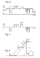
- Fig. 2 the distance (y) over the roadway width (x) is shown, for example when a laser scanner scans the roadway plane (3) transversely.
- a curb (8) On the left you can see a curb (8), an obstacle (9), a hole (10), a black object (14), floating parts (11) and a property (12).
- the distance At the hole (10) the distance is wider than at the road level (3).
- a black object (14) typically no signal is detected.
- the floating parts (11) may be rain, snow or leaves or the like.
- the reflection image changes again during the next scan, so that the suspended parts (11) can classically be distinguished from individual fixed, ie permanent, devices.
- Even the reflection image of fog differs from suspended parts (11) and can be evaluated if necessary.
- the reflection image of fog is also more diffuse and thus differs from suspended parts. It is important to distinguish these different reflections, inter alia, in the assessment of the danger situation in front of a vehicle (2). In the case of suspended parts (11) or fog, there is normally no need to brake; with real obstacles (9) already.
- the property (12) is a permanent facility. It can be used to track a vehicle (2), e.g. along guardrail or wall, or also for location in the direction of travel, e.g. be used on building corners, doors, columns and the like. Even holes (10) in the road level can be used as a location reference.
- the reference line (13) represents the distance values expected at this location on the roadway plane (3). If reference values and measured values match, the lane is as expected. With deviations, an object (6) can be detected or an obstacle (9) or a fault can be detected.
- the Fig. 2 is shown in idealized form.
- the reference line (13) or according to the roadway level (3) are actually further away from the perspective of the sensor (1) right and left, as in the middle. This distortion has been corrected here for better illustration, so that the reference line (13) appears in the road area as a straight line.
- Fig. 3 refers to Fig. 2 and shows the difference between the measured values and the reference values over the lane width. If the measured values correspond to the expected reference values, no difference can be detected. But you can see the deviations through the obstacle (9), the hole (10), the black object (14) and the floating parts (11).
- Fig. 4 shows a sensor (1), for example a camera, on a moving vehicle (2) above the roadway level (3). It should be shown that contrasts at different heights can be detected by tracking the contrasts.
- the marker contrast (16) on the road surface (3) is seen by the sensor (1) in the same direction as the object contrast (17).
- the contrasts seem to have moved further towards the vehicle by the distance (S), as seen by the camera (1).
- the marker contrast (16) now appears offset by a smaller angle (18) and the object contrast (17) is shifted by a larger angle (19).
- the height of the object mark (17) above the road surface (3) and the distance to the sensor (1) or the vehicle (2) can be calculated when the height the sensor (1) above the road surface (3), the distance (S) and the larger angle (19) are known.
- contrasts in the expected image coincide with the next shot, then they lie on the road surface (3); if they do not coincide, they may belong to an object.
- the formation of the expectation picture is a simple process. It is then no longer necessary to use complex computation, if you do not need the true place of contrasts.
- An expectation picture formed from the second picture can be used as a reference for the third picture, and so on.
- stereo cameras Another advantage of this application is the use of stereo cameras. If the stereo camera consists of a right and a left camera, especially contrasts that run longitudinally in the direction of travel can be reliably determined in their distance. By contrast, recordings that take place one after the other, in particular contrasts which run transversely, determine the distance better when the vehicle has traveled a little further. In this respect, the combination of stereo camera and evaluation of various shots on further travel is an advantage.
- FIG. 5 shows in plan view the vehicle (2) on the road surface (3) in front of an object (6).
- the sensor (1) eg laser scanner
- a laser line (20) is scanned over the individual scanning beams (4). Without object (6), the laser line (20) would be in the expected Reference line (13) run.
- the scan line is slightly shorter than on the road surface (3). The expected jump on the curb (8) can also be used for navigation, so to guide the vehicle (2).
- a side strip (31) can be seen on the other side of the road surface (3).
- the texture may be different than on the road surface (3).
- the side strip (31) is detected and can also be used for tracking or could also be assessed as an obstacle.
- the object (6) is recognized as an obstacle.
- the scanning beams (4) are significantly shorter at this point than expected. If, instead of the object (6), a reference line (13) of e.g. 3m would be expected and in the distance a tolerance of perhaps + -0.4m is granted, but the object (6) is detected at a smaller distance of 2.5m, then the object (6) is also an obstacle. In contrast, the roughness on the side strip (31) may be so small that they are still within the tolerance of 0.4m may not be recognized as an obstacle.
- the analysis of the texture can be used as a distinguishing feature, ie for the recognition of objects and levels etc.
- the sensor (1) is at a certain height and looks obliquely on the road surface (3). It can be seen that the outer scanning beams (4) on the traveling plane (3) are longer than the inner scanning beams (4) when they hit the reference line (13). Taking into account the height of the sensor (1) above the road surface (3) and the inclination of the sensor (1), it can be calculated back that the reference line (13) should be more or less depending on the flatness of the road plane (3) a straight line.
- the scanned laser line (20) (actual values) must remain within the tolerance per se.
- the tolerance is exceeded.
- the object (6) must then be recognized to some extent by a certain width and also temporal stability.
- the sensor (1) can be, for example, a laser scanner, a stereo camera, another time-measuring device, but also a pattern projector with a camera (also light-section method) act.
- the patterns can be points, lines, grids, and so on.
- a transverse projection line could correspond to the laser line (20).
- Light-section methods are well suited for small distances indoors. You can then, for example, well recognize differences in the level of the road (3), for example, distinguish a carpet from a parquet floor.
- FIG. 6 is one opposite the FIG. 5 deviating operating situation shown.
- the vehicle (2) is intended to scan the reference line (13) with the sensor (1) per se.
- the laser line (20) extends at a shorter distance and obliquely. This may be because the vehicle (2) is nodding and staggering to the road surface, possibly due to a braking operation or a one-sided loading. It may also be that the road level (3) rises slightly or has a one-sided slope. Perhaps the allowable tolerance to the reference line (13) would now be exceeded. Nevertheless, the situation is not to be assessed as a dangerous situation since the laser line (20) still forms a straight line on the roadway plane (3). There is no interruption or discontinuity in this line.
- FIG. 5 shows how obstacles are detected by absolute distance measurements Fig. 6 in that the flatness is also recognized, even if the tolerances are exceeded in the distance. Only when the linear equation is exceeded inadmissible, an object or obstacle would be detected in the laser line (20).
Landscapes
- Engineering & Computer Science (AREA)
- Physics & Mathematics (AREA)
- Radar, Positioning & Navigation (AREA)
- Remote Sensing (AREA)
- Computer Networks & Wireless Communication (AREA)
- General Physics & Mathematics (AREA)
- Electromagnetism (AREA)
- Traffic Control Systems (AREA)
- Optical Radar Systems And Details Thereof (AREA)
- Measurement Of Optical Distance (AREA)
- Control Of Position, Course, Altitude, Or Attitude Of Moving Bodies (AREA)
- Length Measuring Devices By Optical Means (AREA)
Applications Claiming Priority (2)
| Application Number | Priority Date | Filing Date | Title |
|---|---|---|---|
| DE102011109051 | 2011-07-30 | ||
| DE102011054852.1A DE102011054852B4 (de) | 2011-07-30 | 2011-10-27 | Verfahren zur Erfassung und Bewertung einer Ebene |
Publications (2)
| Publication Number | Publication Date |
|---|---|
| EP2555014A1 true EP2555014A1 (fr) | 2013-02-06 |
| EP2555014B1 EP2555014B1 (fr) | 2018-02-28 |
Family
ID=47022612
Family Applications (1)
| Application Number | Title | Priority Date | Filing Date |
|---|---|---|---|
| EP12401151.1A Active EP2555014B1 (fr) | 2011-07-30 | 2012-07-13 | Procédé de détection et d'évaluation d'un plan |
Country Status (3)
| Country | Link |
|---|---|
| US (1) | US20130030685A1 (fr) |
| EP (1) | EP2555014B1 (fr) |
| DE (1) | DE102011054852B4 (fr) |
Cited By (3)
| Publication number | Priority date | Publication date | Assignee | Title |
|---|---|---|---|---|
| EP3026459A1 (fr) * | 2014-11-27 | 2016-06-01 | Sick Ag | Systeme de capteur |
| WO2017191201A1 (fr) * | 2016-05-06 | 2017-11-09 | Audi Ag | Véhicule automobile comprenant au moins deux capteurs radars |
| EP3453672A1 (fr) | 2017-09-12 | 2019-03-13 | STILL GmbH | Procédé et dispositif de prévention de collision lors du fonctionnement d'un chariot de manutention |
Families Citing this family (23)
| Publication number | Priority date | Publication date | Assignee | Title |
|---|---|---|---|---|
| DE102014209338A1 (de) | 2013-05-17 | 2014-11-20 | Ifm Electronic Gmbh | Lichtlaufzeitkamerasystem zur Freifelderkennung |
| US9165352B2 (en) | 2013-06-10 | 2015-10-20 | Xerox Corporation | Precipitation removal for vision-based parking management systems |
| GB2517788B (en) * | 2013-09-03 | 2016-06-08 | Jaguar Land Rover Ltd | Water depth estimation apparatus and method |
| US9446765B2 (en) | 2014-01-30 | 2016-09-20 | Mobileye Vision Technologies Ltd. | Systems and methods for identifying relevant traffic lights |
| DE102014208967A1 (de) * | 2014-05-13 | 2015-11-19 | Bayerische Motoren Werke Aktiengesellschaft | Umfeldkarte für Fahrflächen mit beliebigem Höhenverlauf |
| DE102014109755A1 (de) * | 2014-07-11 | 2016-01-14 | Sick Ag | Verfahren zur vermessung eines objekts |
| JP6398680B2 (ja) * | 2014-12-12 | 2018-10-03 | 村田機械株式会社 | サイドアーム式移載装置 |
| EP4030378A1 (fr) * | 2015-05-10 | 2022-07-20 | Mobileye Vision Technologies Ltd. | Profil de route le long d'un trajet prévu |
| JP2017015601A (ja) * | 2015-07-02 | 2017-01-19 | シャープ株式会社 | 路面検知装置、移動体、路面検知方法、および路面検知プログラム |
| US9981676B2 (en) | 2016-01-15 | 2018-05-29 | Edward Stanton Sandstrom | Derail alarm systems |
| JP6451715B2 (ja) * | 2016-10-14 | 2019-01-16 | 株式会社豊田自動織機 | フォークリフト |
| DE102017205513B4 (de) * | 2017-03-31 | 2019-08-29 | Zf Friedrichshafen Ag | Verfahren und Vorrichtung zum Einstellen einer Betriebsstrategie für ein Fahrzeug |
| CN108089203A (zh) * | 2018-02-05 | 2018-05-29 | 弗徕威智能机器人科技(上海)有限公司 | 一种特殊障碍物检测方法 |
| US10710593B2 (en) * | 2018-09-04 | 2020-07-14 | GM Global Technology Operations LLC | System and method for autonomous control of a vehicle |
| DE102021201713A1 (de) * | 2021-02-24 | 2022-08-25 | Continental Autonomous Mobility Germany GmbH | Verfahren und Vorrichtung zur Detektion und Höhenbestimmung von Objekten |
| JP2022150929A (ja) * | 2021-03-26 | 2022-10-07 | 本田技研工業株式会社 | 軸ずれ推定装置 |
| CN113071480B (zh) * | 2021-04-30 | 2022-06-03 | 重庆长安汽车股份有限公司 | 自动泊车障碍物检测方法、泊车方法、系统及车辆 |
| DE102021121222A1 (de) | 2021-08-16 | 2023-02-16 | Jungheinrich Aktiengesellschaft | Autonom geführtes Flurförderzeug mit einem Paar von Scanner-Einheiten |
| CN113812889B (zh) * | 2021-09-30 | 2022-11-29 | 深圳银星智能集团股份有限公司 | 一种自移动机器人 |
| EP4478086A4 (fr) * | 2022-02-10 | 2025-11-26 | Pioneer Corp | Dispositif de traitement d'informations, procédé de commande, programme et support de stockage |
| CN116539093B (zh) * | 2023-05-10 | 2025-02-11 | 浙江亿桥工程技术研究有限公司 | 一种建筑工程检测方法 |
| DE102023134781A1 (de) * | 2023-12-12 | 2025-06-12 | Ifm Electronic Gmbh | Verfahren zum Ermitteln der Eigenbewegung eines Fahrzeugs mittels einer Lichtlaufzeitkamera |
| DE102024106659A1 (de) * | 2024-03-08 | 2025-09-11 | Sick Ag | Optischer Sensor |
Citations (2)
| Publication number | Priority date | Publication date | Assignee | Title |
|---|---|---|---|---|
| DE19934670A1 (de) * | 1999-05-26 | 2000-12-21 | Bosch Gmbh Robert | Objektdetektionssystem |
| US20060072914A1 (en) * | 2003-08-28 | 2006-04-06 | Kazuhiko Arai | Object recognition apparatus |
Family Cites Families (21)
| Publication number | Priority date | Publication date | Assignee | Title |
|---|---|---|---|---|
| CA1235773A (fr) * | 1983-12-23 | 1988-04-26 | Shigeto Nakayama | Detecteur d'etat d'une chaussee |
| DE3738221A1 (de) * | 1987-11-11 | 1989-06-08 | Bayerische Motoren Werke Ag | Verfahren und einrichtung zum erkennen des zustandes einer strasse |
| JP2737043B2 (ja) * | 1993-05-12 | 1998-04-08 | 本田技研工業株式会社 | 車両のレーダセンサ装置 |
| JP3212218B2 (ja) * | 1994-05-26 | 2001-09-25 | 三菱電機株式会社 | 車両用障害物検出装置 |
| DE19507957C1 (de) * | 1995-03-07 | 1996-09-12 | Daimler Benz Ag | Fahrzeug mit optischer Abtasteinrichtung für einen seitlichen Fahrbahnbereich |
| DE19652441C2 (de) * | 1996-12-17 | 2002-09-26 | Leuze Electronic Gmbh & Co | Optoelektronische Vorrichtung |
| DE19730414A1 (de) * | 1997-07-16 | 1999-01-21 | Opel Adam Ag | Verfahren und Vorrichtung zur vorausschauenden Fahrbahnbeurteilung |
| DE59809476D1 (de) * | 1997-11-03 | 2003-10-09 | Volkswagen Ag | Autonomes Fahrzeug und Verfahren zur Steuerung eines autonomen Fahrzeuges |
| DE19926559A1 (de) * | 1999-06-11 | 2000-12-21 | Daimler Chrysler Ag | Verfahren und Vorrichtung zur Detektion von Objekten im Umfeld eines Straßenfahrzeugs bis in große Entfernung |
| DE19962491A1 (de) * | 1999-12-23 | 2001-07-05 | Daimler Chrysler Ag | Verfahren zur optischen Überwachung der Umgebung eines sich bewegenden Fahrzeugs |
| KR100523367B1 (ko) * | 2000-10-26 | 2005-10-20 | 마츠시다 덴코 가부시키가이샤 | 장해물 회피기능을 가지는 자율이동장치 |
| US6778897B2 (en) * | 2002-11-27 | 2004-08-17 | Visteon Global Technologies, Inc. | Adaptive cruise control system and strategy |
| DE10351915A1 (de) * | 2003-11-07 | 2005-06-09 | Volkswagen Ag | Überwachungsvorrichtung für ein Kraftfahrzeug |
| GB0403105D0 (en) * | 2004-02-12 | 2004-03-17 | Sim Neil | The safety zone system |
| JP2007187618A (ja) * | 2006-01-16 | 2007-07-26 | Omron Corp | 物体識別装置 |
| DE102006008275A1 (de) * | 2006-02-22 | 2007-08-23 | Siemens Ag | Verfahren zur Detektion von Objekten mit einer schwenkbaren Sensoreinrichtung |
| DE102006012205A1 (de) * | 2006-03-16 | 2007-09-20 | Still Gmbh | Flurförderzeug mit einem Hubmast |
| JP4725391B2 (ja) * | 2006-03-29 | 2011-07-13 | 株式会社デンソー | 車両用視程測定装置、及び運転支援装置 |
| US7872764B2 (en) * | 2007-10-16 | 2011-01-18 | Magna Electronics Inc. | Machine vision for predictive suspension |
| DE102007060346A1 (de) * | 2007-12-14 | 2009-06-18 | Hochschule Offenburg | Verfahren zur Laufzeitmessung mittels Ultraschall, insbesondere zur 2D- oder 3D-Ortung von Objekten |
| JP5039765B2 (ja) * | 2009-09-17 | 2012-10-03 | 日立オートモティブシステムズ株式会社 | 車両制御装置 |
-
2011
- 2011-10-27 DE DE102011054852.1A patent/DE102011054852B4/de active Active
-
2012
- 2012-07-13 EP EP12401151.1A patent/EP2555014B1/fr active Active
- 2012-07-30 US US13/561,149 patent/US20130030685A1/en not_active Abandoned
Patent Citations (2)
| Publication number | Priority date | Publication date | Assignee | Title |
|---|---|---|---|---|
| DE19934670A1 (de) * | 1999-05-26 | 2000-12-21 | Bosch Gmbh Robert | Objektdetektionssystem |
| US20060072914A1 (en) * | 2003-08-28 | 2006-04-06 | Kazuhiko Arai | Object recognition apparatus |
Cited By (5)
| Publication number | Priority date | Publication date | Assignee | Title |
|---|---|---|---|---|
| EP3026459A1 (fr) * | 2014-11-27 | 2016-06-01 | Sick Ag | Systeme de capteur |
| DE102014117399B4 (de) * | 2014-11-27 | 2017-05-11 | Sick Ag | Sensorsystem |
| WO2017191201A1 (fr) * | 2016-05-06 | 2017-11-09 | Audi Ag | Véhicule automobile comprenant au moins deux capteurs radars |
| EP3453672A1 (fr) | 2017-09-12 | 2019-03-13 | STILL GmbH | Procédé et dispositif de prévention de collision lors du fonctionnement d'un chariot de manutention |
| EP3453672B1 (fr) * | 2017-09-12 | 2025-04-16 | STILL GmbH | Procédé et dispositif de prévention de collision lors du fonctionnement d'un chariot de manutention |
Also Published As
| Publication number | Publication date |
|---|---|
| DE102011054852B4 (de) | 2024-05-16 |
| EP2555014B1 (fr) | 2018-02-28 |
| DE102011054852A1 (de) | 2013-01-31 |
| US20130030685A1 (en) | 2013-01-31 |
Similar Documents
| Publication | Publication Date | Title |
|---|---|---|
| EP2555014B1 (fr) | Procédé de détection et d'évaluation d'un plan | |
| EP1557691B1 (fr) | Procédé de détection des marquages sur une chaussée | |
| DE102007021762B4 (de) | Straßenumgebungs-Erkennungsvorrichtung und Verfahren zum Erkennen einer Straßenumgebung | |
| EP1067399B1 (fr) | Procédé de détermination de la visibilité | |
| EP4139709B1 (fr) | Procédé et dispositif d'identification de l'efflorescence dans une mesure lidar | |
| EP1068992A2 (fr) | Aide pour reculer | |
| WO2016120044A1 (fr) | Mesure d'une dimension sur une surface | |
| EP1286178A2 (fr) | Procédé de détection optique du sol | |
| WO2009089938A1 (fr) | Système et procédé pour mesurer un créneau de stationnement | |
| DE102004057296A1 (de) | Lane-Departure-Warning mit Unterscheidung zwischen Fahrbahnrandmarkierung und baulicher Begrenzung des Fahrbahnrandes | |
| DE102008004633A1 (de) | Verfahren und Vorrichtung zur Erkennung und/oder Vermessung einer Parklücke | |
| DE10114932A1 (de) | Dreidimensionale Umfelderfassung | |
| DE112015000715T5 (de) | Vorrichtung zum Erfassen einer Achsenfehlausrichtung eines Strahlensensors | |
| EP3789842B1 (fr) | Procédé de localisation d'un véhicule ainsi que véhicule destiné à la mise en uvre du procédé | |
| WO2003087873A1 (fr) | Determination de l'orientation d'un capteur optoelectronique | |
| DE102017212371B4 (de) | Bestimmung einer Marke in einem Datensatz mit mittels zumindest eines Laserscanners erfassten dreidimensionalen Oberflächen-Koordinaten einer Szene | |
| EP4237990A1 (fr) | Procédé et dispositif d'identification de candidats d'efflorescence dans une mesure lidar | |
| EP3026459B1 (fr) | Systeme de capteur | |
| EP3193276A1 (fr) | Dispositif de detection et procede destine a la reconnaissance d'essieux de vehicule | |
| EP1628141B1 (fr) | Procède de triangulation ayant des diodes laser et une caméra pour determiner la distance pour les applications arret-demarrage des véhicules automobiles | |
| EP2959310A1 (fr) | Procédé et dispositif pour déterminer l'étendue de détection d'une voie de circulation | |
| EP3995856A1 (fr) | Méthode de mesure de la position, systèmes de mesure de la position et marquage | |
| DE102009038406B4 (de) | Verfahren und Vorrichtung zur Vermessung des Umfeldes eines Kraftfahrzeugs | |
| WO2022157042A1 (fr) | Détection de l'extrémité latérale d'une chaussée | |
| DE102011017707A1 (de) | Verfahren und Vorrichtung zur Erkennung von einem Objekt in einer Umgebung einer Kamera |
Legal Events
| Date | Code | Title | Description |
|---|---|---|---|
| PUAI | Public reference made under article 153(3) epc to a published international application that has entered the european phase |
Free format text: ORIGINAL CODE: 0009012 |
|
| AK | Designated contracting states |
Kind code of ref document: A1 Designated state(s): AL AT BE BG CH CY CZ DE DK EE ES FI FR GB GR HR HU IE IS IT LI LT LU LV MC MK MT NL NO PL PT RO RS SE SI SK SM TR |
|
| AX | Request for extension of the european patent |
Extension state: BA ME |
|
| RIN1 | Information on inventor provided before grant (corrected) |
Inventor name: GOETTING, HANS-HEINRICH |
|
| 17P | Request for examination filed |
Effective date: 20130806 |
|
| RBV | Designated contracting states (corrected) |
Designated state(s): AL AT BE BG CH CY CZ DE DK EE ES FI FR GB GR HR HU IE IS IT LI LT LU LV MC MK MT NL NO PL PT RO RS SE SI SK SM TR |
|
| 17Q | First examination report despatched |
Effective date: 20160527 |
|
| GRAP | Despatch of communication of intention to grant a patent |
Free format text: ORIGINAL CODE: EPIDOSNIGR1 |
|
| STAA | Information on the status of an ep patent application or granted ep patent |
Free format text: STATUS: GRANT OF PATENT IS INTENDED |
|
| INTG | Intention to grant announced |
Effective date: 20171206 |
|
| GRAS | Grant fee paid |
Free format text: ORIGINAL CODE: EPIDOSNIGR3 |
|
| GRAA | (expected) grant |
Free format text: ORIGINAL CODE: 0009210 |
|
| STAA | Information on the status of an ep patent application or granted ep patent |
Free format text: STATUS: THE PATENT HAS BEEN GRANTED |
|
| AK | Designated contracting states |
Kind code of ref document: B1 Designated state(s): AL AT BE BG CH CY CZ DE DK EE ES FI FR GB GR HR HU IE IS IT LI LT LU LV MC MK MT NL NO PL PT RO RS SE SI SK SM TR |
|
| REG | Reference to a national code |
Ref country code: GB Ref legal event code: FG4D Free format text: NOT ENGLISH Ref country code: CH Ref legal event code: EP |
|
| REG | Reference to a national code |
Ref country code: AT Ref legal event code: REF Ref document number: 974741 Country of ref document: AT Kind code of ref document: T Effective date: 20180315 |
|
| REG | Reference to a national code |
Ref country code: IE Ref legal event code: FG4D Free format text: LANGUAGE OF EP DOCUMENT: GERMAN |
|
| REG | Reference to a national code |
Ref country code: DE Ref legal event code: R096 Ref document number: 502012012244 Country of ref document: DE |
|
| REG | Reference to a national code |
Ref country code: NL Ref legal event code: MP Effective date: 20180228 |
|
| REG | Reference to a national code |
Ref country code: LT Ref legal event code: MG4D |
|
| REG | Reference to a national code |
Ref country code: FR Ref legal event code: PLFP Year of fee payment: 7 |
|
| PG25 | Lapsed in a contracting state [announced via postgrant information from national office to epo] |
Ref country code: ES Free format text: LAPSE BECAUSE OF FAILURE TO SUBMIT A TRANSLATION OF THE DESCRIPTION OR TO PAY THE FEE WITHIN THE PRESCRIBED TIME-LIMIT Effective date: 20180228 Ref country code: NL Free format text: LAPSE BECAUSE OF FAILURE TO SUBMIT A TRANSLATION OF THE DESCRIPTION OR TO PAY THE FEE WITHIN THE PRESCRIBED TIME-LIMIT Effective date: 20180228 Ref country code: LT Free format text: LAPSE BECAUSE OF FAILURE TO SUBMIT A TRANSLATION OF THE DESCRIPTION OR TO PAY THE FEE WITHIN THE PRESCRIBED TIME-LIMIT Effective date: 20180228 Ref country code: CY Free format text: LAPSE BECAUSE OF FAILURE TO SUBMIT A TRANSLATION OF THE DESCRIPTION OR TO PAY THE FEE WITHIN THE PRESCRIBED TIME-LIMIT Effective date: 20180228 Ref country code: NO Free format text: LAPSE BECAUSE OF FAILURE TO SUBMIT A TRANSLATION OF THE DESCRIPTION OR TO PAY THE FEE WITHIN THE PRESCRIBED TIME-LIMIT Effective date: 20180528 Ref country code: HR Free format text: LAPSE BECAUSE OF FAILURE TO SUBMIT A TRANSLATION OF THE DESCRIPTION OR TO PAY THE FEE WITHIN THE PRESCRIBED TIME-LIMIT Effective date: 20180228 Ref country code: FI Free format text: LAPSE BECAUSE OF FAILURE TO SUBMIT A TRANSLATION OF THE DESCRIPTION OR TO PAY THE FEE WITHIN THE PRESCRIBED TIME-LIMIT Effective date: 20180228 |
|
| PG25 | Lapsed in a contracting state [announced via postgrant information from national office to epo] |
Ref country code: RS Free format text: LAPSE BECAUSE OF FAILURE TO SUBMIT A TRANSLATION OF THE DESCRIPTION OR TO PAY THE FEE WITHIN THE PRESCRIBED TIME-LIMIT Effective date: 20180228 Ref country code: GR Free format text: LAPSE BECAUSE OF FAILURE TO SUBMIT A TRANSLATION OF THE DESCRIPTION OR TO PAY THE FEE WITHIN THE PRESCRIBED TIME-LIMIT Effective date: 20180529 Ref country code: BG Free format text: LAPSE BECAUSE OF FAILURE TO SUBMIT A TRANSLATION OF THE DESCRIPTION OR TO PAY THE FEE WITHIN THE PRESCRIBED TIME-LIMIT Effective date: 20180528 Ref country code: LV Free format text: LAPSE BECAUSE OF FAILURE TO SUBMIT A TRANSLATION OF THE DESCRIPTION OR TO PAY THE FEE WITHIN THE PRESCRIBED TIME-LIMIT Effective date: 20180228 Ref country code: SE Free format text: LAPSE BECAUSE OF FAILURE TO SUBMIT A TRANSLATION OF THE DESCRIPTION OR TO PAY THE FEE WITHIN THE PRESCRIBED TIME-LIMIT Effective date: 20180228 |
|
| PG25 | Lapsed in a contracting state [announced via postgrant information from national office to epo] |
Ref country code: MT Free format text: LAPSE BECAUSE OF FAILURE TO SUBMIT A TRANSLATION OF THE DESCRIPTION OR TO PAY THE FEE WITHIN THE PRESCRIBED TIME-LIMIT Effective date: 20180228 |
|
| PG25 | Lapsed in a contracting state [announced via postgrant information from national office to epo] |
Ref country code: RO Free format text: LAPSE BECAUSE OF FAILURE TO SUBMIT A TRANSLATION OF THE DESCRIPTION OR TO PAY THE FEE WITHIN THE PRESCRIBED TIME-LIMIT Effective date: 20180228 Ref country code: PL Free format text: LAPSE BECAUSE OF FAILURE TO SUBMIT A TRANSLATION OF THE DESCRIPTION OR TO PAY THE FEE WITHIN THE PRESCRIBED TIME-LIMIT Effective date: 20180228 Ref country code: AL Free format text: LAPSE BECAUSE OF FAILURE TO SUBMIT A TRANSLATION OF THE DESCRIPTION OR TO PAY THE FEE WITHIN THE PRESCRIBED TIME-LIMIT Effective date: 20180228 Ref country code: IT Free format text: LAPSE BECAUSE OF FAILURE TO SUBMIT A TRANSLATION OF THE DESCRIPTION OR TO PAY THE FEE WITHIN THE PRESCRIBED TIME-LIMIT Effective date: 20180228 Ref country code: EE Free format text: LAPSE BECAUSE OF FAILURE TO SUBMIT A TRANSLATION OF THE DESCRIPTION OR TO PAY THE FEE WITHIN THE PRESCRIBED TIME-LIMIT Effective date: 20180228 |
|
| REG | Reference to a national code |
Ref country code: DE Ref legal event code: R097 Ref document number: 502012012244 Country of ref document: DE |
|
| PG25 | Lapsed in a contracting state [announced via postgrant information from national office to epo] |
Ref country code: DK Free format text: LAPSE BECAUSE OF FAILURE TO SUBMIT A TRANSLATION OF THE DESCRIPTION OR TO PAY THE FEE WITHIN THE PRESCRIBED TIME-LIMIT Effective date: 20180228 Ref country code: SM Free format text: LAPSE BECAUSE OF FAILURE TO SUBMIT A TRANSLATION OF THE DESCRIPTION OR TO PAY THE FEE WITHIN THE PRESCRIBED TIME-LIMIT Effective date: 20180228 Ref country code: SK Free format text: LAPSE BECAUSE OF FAILURE TO SUBMIT A TRANSLATION OF THE DESCRIPTION OR TO PAY THE FEE WITHIN THE PRESCRIBED TIME-LIMIT Effective date: 20180228 Ref country code: CZ Free format text: LAPSE BECAUSE OF FAILURE TO SUBMIT A TRANSLATION OF THE DESCRIPTION OR TO PAY THE FEE WITHIN THE PRESCRIBED TIME-LIMIT Effective date: 20180228 |
|
| PLBE | No opposition filed within time limit |
Free format text: ORIGINAL CODE: 0009261 |
|
| STAA | Information on the status of an ep patent application or granted ep patent |
Free format text: STATUS: NO OPPOSITION FILED WITHIN TIME LIMIT |
|
| 26N | No opposition filed |
Effective date: 20181129 |
|
| PG25 | Lapsed in a contracting state [announced via postgrant information from national office to epo] |
Ref country code: SI Free format text: LAPSE BECAUSE OF FAILURE TO SUBMIT A TRANSLATION OF THE DESCRIPTION OR TO PAY THE FEE WITHIN THE PRESCRIBED TIME-LIMIT Effective date: 20180228 |
|
| REG | Reference to a national code |
Ref country code: CH Ref legal event code: PL |
|
| PG25 | Lapsed in a contracting state [announced via postgrant information from national office to epo] |
Ref country code: LU Free format text: LAPSE BECAUSE OF NON-PAYMENT OF DUE FEES Effective date: 20180713 Ref country code: MC Free format text: LAPSE BECAUSE OF FAILURE TO SUBMIT A TRANSLATION OF THE DESCRIPTION OR TO PAY THE FEE WITHIN THE PRESCRIBED TIME-LIMIT Effective date: 20180228 |
|
| REG | Reference to a national code |
Ref country code: BE Ref legal event code: MM Effective date: 20180731 |
|
| REG | Reference to a national code |
Ref country code: IE Ref legal event code: MM4A |
|
| PG25 | Lapsed in a contracting state [announced via postgrant information from national office to epo] |
Ref country code: IE Free format text: LAPSE BECAUSE OF NON-PAYMENT OF DUE FEES Effective date: 20180713 Ref country code: LI Free format text: LAPSE BECAUSE OF NON-PAYMENT OF DUE FEES Effective date: 20180731 Ref country code: CH Free format text: LAPSE BECAUSE OF NON-PAYMENT OF DUE FEES Effective date: 20180731 |
|
| PG25 | Lapsed in a contracting state [announced via postgrant information from national office to epo] |
Ref country code: BE Free format text: LAPSE BECAUSE OF NON-PAYMENT OF DUE FEES Effective date: 20180731 |
|
| REG | Reference to a national code |
Ref country code: AT Ref legal event code: MM01 Ref document number: 974741 Country of ref document: AT Kind code of ref document: T Effective date: 20180713 |
|
| PG25 | Lapsed in a contracting state [announced via postgrant information from national office to epo] |
Ref country code: AT Free format text: LAPSE BECAUSE OF NON-PAYMENT OF DUE FEES Effective date: 20180713 |
|
| PG25 | Lapsed in a contracting state [announced via postgrant information from national office to epo] |
Ref country code: TR Free format text: LAPSE BECAUSE OF FAILURE TO SUBMIT A TRANSLATION OF THE DESCRIPTION OR TO PAY THE FEE WITHIN THE PRESCRIBED TIME-LIMIT Effective date: 20180228 |
|
| PG25 | Lapsed in a contracting state [announced via postgrant information from national office to epo] |
Ref country code: PT Free format text: LAPSE BECAUSE OF FAILURE TO SUBMIT A TRANSLATION OF THE DESCRIPTION OR TO PAY THE FEE WITHIN THE PRESCRIBED TIME-LIMIT Effective date: 20180228 Ref country code: HU Free format text: LAPSE BECAUSE OF FAILURE TO SUBMIT A TRANSLATION OF THE DESCRIPTION OR TO PAY THE FEE WITHIN THE PRESCRIBED TIME-LIMIT; INVALID AB INITIO Effective date: 20120713 |
|
| PG25 | Lapsed in a contracting state [announced via postgrant information from national office to epo] |
Ref country code: MK Free format text: LAPSE BECAUSE OF NON-PAYMENT OF DUE FEES Effective date: 20180228 |
|
| PG25 | Lapsed in a contracting state [announced via postgrant information from national office to epo] |
Ref country code: IS Free format text: LAPSE BECAUSE OF FAILURE TO SUBMIT A TRANSLATION OF THE DESCRIPTION OR TO PAY THE FEE WITHIN THE PRESCRIBED TIME-LIMIT Effective date: 20180628 |
|
| REG | Reference to a national code |
Ref country code: DE Ref legal event code: R082 Ref document number: 502012012244 Country of ref document: DE Representative=s name: CREUTZBURG, TOM, DIPL.-ING., DE |
|
| PGFP | Annual fee paid to national office [announced via postgrant information from national office to epo] |
Ref country code: DE Payment date: 20250731 Year of fee payment: 14 |
|
| PGFP | Annual fee paid to national office [announced via postgrant information from national office to epo] |
Ref country code: GB Payment date: 20250724 Year of fee payment: 14 |
|
| PGFP | Annual fee paid to national office [announced via postgrant information from national office to epo] |
Ref country code: FR Payment date: 20250723 Year of fee payment: 14 |