EP2555331B1 - Borne de mise à la terre - Google Patents
Borne de mise à la terre Download PDFInfo
- Publication number
- EP2555331B1 EP2555331B1 EP12177775.9A EP12177775A EP2555331B1 EP 2555331 B1 EP2555331 B1 EP 2555331B1 EP 12177775 A EP12177775 A EP 12177775A EP 2555331 B1 EP2555331 B1 EP 2555331B1
- Authority
- EP
- European Patent Office
- Prior art keywords
- earth terminal
- contact
- guide means
- earthed
- contact element
- Prior art date
- Legal status (The legal status is an assumption and is not a legal conclusion. Google has not performed a legal analysis and makes no representation as to the accuracy of the status listed.)
- Active
Links
Images


Classifications
-
- H—ELECTRICITY
- H01—ELECTRIC ELEMENTS
- H01R—ELECTRICALLY-CONDUCTIVE CONNECTIONS; STRUCTURAL ASSOCIATIONS OF A PLURALITY OF MUTUALLY-INSULATED ELECTRICAL CONNECTING ELEMENTS; COUPLING DEVICES; CURRENT COLLECTORS
- H01R4/00—Electrically-conductive connections between two or more conductive members in direct contact, i.e. touching one another; Means for effecting or maintaining such contact; Electrically-conductive connections having two or more spaced connecting locations for conductors and using contact members penetrating insulation
- H01R4/58—Electrically-conductive connections between two or more conductive members in direct contact, i.e. touching one another; Means for effecting or maintaining such contact; Electrically-conductive connections having two or more spaced connecting locations for conductors and using contact members penetrating insulation characterised by the form or material of the contacting members
- H01R4/64—Connections between or with conductive parts having primarily a non-electric function, e.g. frame, casing, rail
-
- H—ELECTRICITY
- H01—ELECTRIC ELEMENTS
- H01R—ELECTRICALLY-CONDUCTIVE CONNECTIONS; STRUCTURAL ASSOCIATIONS OF A PLURALITY OF MUTUALLY-INSULATED ELECTRICAL CONNECTING ELEMENTS; COUPLING DEVICES; CURRENT COLLECTORS
- H01R4/00—Electrically-conductive connections between two or more conductive members in direct contact, i.e. touching one another; Means for effecting or maintaining such contact; Electrically-conductive connections having two or more spaced connecting locations for conductors and using contact members penetrating insulation
- H01R4/58—Electrically-conductive connections between two or more conductive members in direct contact, i.e. touching one another; Means for effecting or maintaining such contact; Electrically-conductive connections having two or more spaced connecting locations for conductors and using contact members penetrating insulation characterised by the form or material of the contacting members
- H01R4/66—Connections with the terrestrial mass, e.g. earth plate, earth pin
Definitions
- the invention relates to a ground terminal.
- Earthing terminals for grounding of eg water pipes or for equipotential bonding are available in various forms on the market.
- Out US2010227483 is a ground terminal known, which consists of two half-shells which are screwed together via two lateral flanges. A clamping device for fixing a grounding wire is firmly formed on one of the two half-shells. The half-shells make contact with the pipe. To mount the ground terminal, the two half-shells are placed around the pipe to be grounded and fastened by means of screws.
- grounding terminals comprising a clamping device, which is laterally connected to a mounting portion.
- a metal band is fixed with one end fixed to the attachment portion and can be inserted with the free end in a guide element of the attachment portion.
- the metal strip is placed around the pipe and the free end of the metal strip is inserted into the guide member and fixed by a screw in the mounting portion by deformation of the tape perpendicular to its surface.
- Such grounding terminals are cumbersome to install and the type of fixation leads to an insufficient clamping force. In addition, they are not easy solvable and reusable.
- EP1398850 The same applicant describes a ground terminal with a clamping device, which is arranged directly on a support member.
- the support member has two laterally bent by 90 degrees contact elements, which the contact to grounding device.
- the support member has two free-standing, bent back and arranged transversely to the contact elements tabs that allow attachment of the ground terminal by means of a band clip, but do not rest on the device to be grounded.
- the ground terminal has many undercuts, which complicate a cost-effective production.
- it has long load paths between the tabs and the contact elements and the entire ground terminal can deform unintentionally at the high clamping forces of a band clamp, which can lead to insufficient contact.
- the object of the invention is to provide a ground terminal, which is easier and less expensive to produce and allows better contact with the device to be grounded.
- the above object is achieved by a ground terminal with the features of claim 1.
- the earthing terminal according to the invention comprising a clamping device for at least one earthing line and a fastening section with which the earthing terminal can be fastened to a device to be earthed by means of a guided clamp, wherein the fastening section has at least one guide means for guiding the clamp, is accordingly characterized in that Attachment section has at least one contact element for resting on the device to be grounded, wherein the at least one guide portion and the at least a contact element are arranged adjacent to each other in such a way that in the mounted state of the ground terminal clamped on a device to be grounded, the contact element between the pipe clamp and the device to be grounded and thus fixed.
- another suitable fastening means such as a band clamp, Bride, hose clamp, wire clamp or the like, can be used.
- the ground terminal can be used e.g. be adapted to different diameters.
- the at least one contact element of the grounding terminal according to the invention is preferably a contact plate.
- the contact surface of the ground terminal can be significantly increased, which allows an even better contact.
- such a contact plate may be angled or rounded, and / or be deformable and / or have a predetermined bending point, so that the bearing surface resp.
- Contact surface of the contact plate on a device to be grounded, preferably a pipe, is further enlarged.
- the at least one guide means is arranged laterally adjacent to the at least one contact plate.
- a guide section is arranged at two opposite ends or sides of the contact element, so that in the mounted state of the ground terminal on a device to be grounded, the clamp extends over the contact element.
- the at least one guide section lies between two contact elements, so that in the mounted state of the ground terminal on a device to be earthed, the pipe clamp runs over the contact element.
- the at least one guide means may be preferably formed as a tab or slot-shaped recess through which the pipe clamp to be attached extends.
- the at least one guide means may also be designed as two webs or two tongues, so that the pipe clamp to be attached extends between the webs or tongues and over the contact element.
- the type of guide means can be chosen according to their arrangement in the various embodiments.
- this is preferably angled or rounded, so that the bearing surface of the contact plate on a device to be grounded, preferably a pipe, is enlarged.
- the contact element preferably the contact plate, may be about 20 to 40 mm, preferably 25 to 30 mm, wide and about 20 to 40 mm, preferably 25 to 30 mm long.
- the clamping device can be arranged via a connecting portion transverse to the direction of the pipe clamp.
- the clamping device can also be arranged on the attachment section via a connecting section along the running direction of the clamp be, in which case at least one guide means is formed by a slot-shaped recess in the connecting portion.
- the attachment portion and a portion of the clamping device are preferably integrally stamped and / or bent together from a steel sheet.
- the steel sheet may be about 1 to 3 mm, preferably about 2 mm, thick.
- a per se known band clamp or strap e.g. with a sortedspannver gleich
- a pipe clamp with lock and strap can be easily attached by the guide means.
- Other fasteners, provided they fit in the guide means, can also be used.
- the earthing clamp is, as long as the clamp is not tightened, freely slidable along the clamp, so that the clamp of the clamp and the clamp can be brought into the desired positions.
- the closure resp. the lock of the clamp and the clamping device are therefore variably arranged.
- the inventive earthing terminal is reusable, since the clamp can be removed without destroying or can simply be replaced by a new pipe clamp.
- the invention further relates to a kit of a ground terminal according to the invention and a pipe clamp, preferably a band clamp with lock and strap, more preferably a band clamp with sortedspannver gleich as a lock.
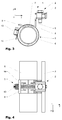
- Fig. 1 to 4 are a first embodiment of the inventive ground terminal 1 in perspective views ( Fig. 1 and 2 ), or a side view ( Fig. 3 ) and a plan view ( Fig. 4 ).
- the ground terminal 1 is shown with a band clamp 5 with lock 13 and strap 14 on a pipe to be grounded 6, wherein the band clamp not tightened.
- the ground terminal 1 has a known clamping device with clamping plate and clamping screw.
- a grounding line 3 is clamped.
- the grounding line 3 may be, for example, a wire, a stranded wire, a rope, a cable or the like.
- the earthing terminal 1 further comprises a fastening section 4 with a contact element designed as a contact plate 7, which rests on the tube 6.
- the contact plate 7 is angled centrally, so that the support surface is enlarged to the tube 6.
- the attachment portion 4 on two opposite sides of the contact plate 7 each about 90 degrees bent parts, in which a slot-shaped recess 8 are formed as a guide means for the band clamp 5.
- the slot-shaped recesses 8 extend beyond the bent region, so that the clamping force of the pipe clamp 5 is transmitted via the clamping band 14 directly to the contact plate 7.
- the bent part is continued as a connecting portion 9 for the clamping device 2.
- the connecting portion 9 is therefore arranged in the running direction of the tension band 14 of the pipe clip 5 on the attachment portion 4.
- the guide means 8 at the free end, ie the clamping device 2, respectively. the connecting portion 9, opposite end, may also be formed as two webs or tongues, between which the pipe clamp 5 can be performed.
- Fig. 3 shows the embodiment in a side view with a view along the longitudinal axis of the tube 6. This illustration clearly shows the enlarged bearing surface of the angled contact plate. 7
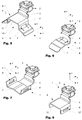
- Fig. 5 also shows the embodiment Fig. 1 in a perspective view, wherein the ground terminal 1 is shown detached from the pipe clamp 5 with lock 13 and strap 14.
- a clamp can also be another suitable fastener be used.
- the contact plate 7 also has a predetermined bending point 15. The predetermined bending point 15 is arranged such that when attaching the ground terminal 1 on a pipe to be grounded 5, a portion of the contact plate under the clamping pressure of the pipe clip 5 turns towards the pipe, whereby the contacting of the ground terminal 1 is increased to the tube 5.
- a second embodiment of the inventive ground terminal 1 is shown in a perspective view.
- the connecting portion 9 opposite side of the contact plate 7 no guide means 8.
- the pipe clamp 5 (not shown) is guided with the clamping band 14 through the slot-shaped recess in the connecting portion 9 and extends over the contact plate. 7
- a third embodiment of the inventive ground terminal 1 is shown in a perspective view.
- the clamping device 2 is connected via a connecting portion 9 with the contact plate 7, wherein the connecting portion 9 arranged transversely to the direction of the pipe clamp on one side of the contact plate, which is between the two guide means 8, 8 '.
- both guide means 8, 8 ' may be formed as webs or tongues.
- a fourth embodiment of the inventive ground terminal 1 is shown in a perspective view.
- the contact element as two connected via a bridge 10 contact plates 7, 7 'is formed.
- Two guide means 8, 8 ' are each formed in bent parts between the contact plates 7, 7' and the bridge 10.
- the pipe clamp 5 (not shown) is with the clamping band through the slot-shaped recess in the bent parts 11, 11 'out, wherein the clamping band 14 under the bridge and over the contact plates 7, 7' extends.
- a fifth embodiment of the inventive ground terminal 1 is shown in a perspective view.
- the contact element as webs 12, 12 'formed directly below the guide means 8, 8'.
Landscapes
- Supports For Pipes And Cables (AREA)
- Clamps And Clips (AREA)
Claims (15)
- Borne de mise à la terre (1) comprenant un dispositif de serrage (2) pour au moins un câble de mise à la terre (3) et une section de fixation (4) à l'aide de laquelle la borne de mise à la terre (1) peut être fixée au moyen d'un collier de serrage guidé librement (5) au niveau d'un dispositif à mettre à la terre (6), la section de fixation (4) présentant au moins un moyen de guidage (8) pour guider le collier de serrage (5), la section de fixation (4) présentant au moins un élément de contact (7) destiné à se poser sur le dispositif à mettre à la terre (6), caractérisée en ce que l'au moins un moyen de guidage (8) et l'au moins un élément de contact (7) sont disposés adjacents l'un par rapport à l'autre de manière à ce que, à l'état monté de la borne de mise à la terre (1) sur un dispositif à mettre à la terre (6), l'élément de contact (7) soit bloqué entre le collier de serrage (5) et le dispositif à mettre à la terre (6).
- Borne de mise à la terre (1) selon la revendication 1, caractérisée en ce que l'au moins un élément de contact (7) est une plaque de contact.
- Borne de mise à la terre (1) selon la revendication 2, caractérisée en ce que l'au moins un moyen de guidage (8) est disposé latéralement adjacent à l'au moins une plaque de contact (7).
- Borne de mise à la terre (1) selon la revendication 2 ou 3, caractérisée en ce que la plaque de contact (7) est déformable et/ou présente un point de flexion théorique (15) de sorte que, à l'état monté de la borne de mise à la terre (1) sur le dispositif à mettre à la terre, le contact de la plaque de contact (7) avec le dispositif à mettre à la terre (6) soit accru.
- Borne de mise à la terre (1) selon une des revendications 1 à 4, caractérisée en ce que l'au moins un moyen de guidage (8) se présente sous forme d'une bride ou d'un évidement en forme de fente.
- Borne de mise à la terre (1) selon une des revendications 1 à 4, caractérisée en ce que l'au moins un moyen de guidage (8) se présente sous forme de deux traverses ou deux languettes.
- Borne de mise à la terre (1) selon une des revendications 2 à 6, caractérisée en ce que la plaque de contact (7) est angulaire ou arrondie, de sorte que la surface de contact de la plaque de contact (7) sur un dispositif à mettre à la terre (6), de préférence un tuyau, est agrandie.
- Borne de mise à la terre (1) selon une des revendications précédentes, caractérisée en ce que l'élément de contact (7) a une largeur d'environ 20 à 40 mm, de préférence 25 à 30 mm, et une longueur d'environ 20 à 40 mm, de préférence 25 à 30 mm.
- Borne de mise à la terre selon une des revendications précédentes, caractérisé en ce qu'un moyen de guidage (8) est disposé respectivement sur deux faces opposées de l'élément de contact (7) de sorte que, à l'état monté de la borne de mise à la terre (1) sur un dispositif à mettre à la terre (6), le collier de serrage (5) s'étend au-dessus de l'élément de contact (7).
- Borne de mise à la terre selon une des revendications 1 à 8, caractérisée en ce que l'au moins un moyen de guidage (8) est situé entre deux éléments de contact (7) de sorte que, à l'état monté de la borne de mise à la terre (1) sur un dispositif à mettre à la terre (6), le collier de serrage (5) s'étend au-dessus des éléments de contact (7).
- Borne de mise à la terre selon une des revendications précédentes, caractérisée en ce que le dispositif de serrage (2) est disposé via une section de liaison (9) transversalement par rapport au sens de roulement du collier de serrage (5).
- Borne de mise à la terre selon une des revendications 1 à 10, caractérisée en ce que le dispositif de serrage (2) est disposé via une section de liaison (9) le long du sens de roulement du collier de serrage (5) au niveau de la section de fixation (4) et qu'au moins un moyen de guidage (8) est constitué par un évidement en forme de fente de la section de liaison (9).
- Borne de mise à la terre selon une des revendications précédentes, caractérisée en ce que la section de fixation (4) est découpée et/ou cintrée en une pièce dans une tôle d'acier avec une partie du dispositif de serrage (2).
- Borne de mise à la terre selon la revendication 13, caractérisée en ce que la tôle d'acier a une épaisseur d'environ 1 à 3 mm, de préférence environ 2 mm.
- Kit comportant une borne de mise à la terre selon une des revendications 1 à 13 et un collier de serrage, de préférence un collier en bande (5) avec serrure (13) et bande de tension (14).
Applications Claiming Priority (1)
| Application Number | Priority Date | Filing Date | Title |
|---|---|---|---|
| CH12942011A CH705346A2 (de) | 2011-08-04 | 2011-08-04 | Erdungsklemme. |
Publications (2)
| Publication Number | Publication Date |
|---|---|
| EP2555331A1 EP2555331A1 (fr) | 2013-02-06 |
| EP2555331B1 true EP2555331B1 (fr) | 2016-09-14 |
Family
ID=46650378
Family Applications (1)
| Application Number | Title | Priority Date | Filing Date |
|---|---|---|---|
| EP12177775.9A Active EP2555331B1 (fr) | 2011-08-04 | 2012-07-25 | Borne de mise à la terre |
Country Status (2)
| Country | Link |
|---|---|
| EP (1) | EP2555331B1 (fr) |
| CH (1) | CH705346A2 (fr) |
Cited By (1)
| Publication number | Priority date | Publication date | Assignee | Title |
|---|---|---|---|---|
| US11649910B2 (en) | 2020-03-06 | 2023-05-16 | Erico International Corporation | Systems and methods for a clamp |
Families Citing this family (2)
| Publication number | Priority date | Publication date | Assignee | Title |
|---|---|---|---|---|
| CH708053A2 (de) * | 2013-05-14 | 2014-11-14 | Agro Ag | Unterputzdose für elektrische Anschlüsse. |
| CH711109B1 (de) * | 2015-05-20 | 2020-03-13 | Agro Ag | Klemmvorrichtung für eine Erdungsklemme und Erdungsklemme. |
Family Cites Families (5)
| Publication number | Priority date | Publication date | Assignee | Title |
|---|---|---|---|---|
| DE3502022A1 (de) | 1983-09-08 | 1986-07-24 | Hermann Kleinhuis GmbH & Co KG, 5880 Lüdenscheid | Erdungsbandschelle mit universalanschlussklemme |
| DE3332353A1 (de) | 1983-09-08 | 1985-03-28 | Hermann Kleinhuis GmbH & Co KG, 5880 Lüdenscheid | Erdungsbandschelle mit universalanschlussklemme |
| US6202300B1 (en) * | 1998-06-05 | 2001-03-20 | Chrysler Corporation | Method for electrical grounding of vehicular components |
| DE50203970D1 (de) | 2002-09-05 | 2005-09-22 | Agro Ag Hunzenschwil | Erdleitungsbride |
| US7780461B1 (en) | 2009-03-03 | 2010-08-24 | Mike Vernica | Midpoint cable electrical ground clamp |
-
2011
- 2011-08-04 CH CH12942011A patent/CH705346A2/de not_active Application Discontinuation
-
2012
- 2012-07-25 EP EP12177775.9A patent/EP2555331B1/fr active Active
Cited By (2)
| Publication number | Priority date | Publication date | Assignee | Title |
|---|---|---|---|---|
| US11649910B2 (en) | 2020-03-06 | 2023-05-16 | Erico International Corporation | Systems and methods for a clamp |
| US12215809B2 (en) | 2020-03-06 | 2025-02-04 | Erico International Corporation | Systems and methods for a clamp |
Also Published As
| Publication number | Publication date |
|---|---|
| EP2555331A1 (fr) | 2013-02-06 |
| CH705346A2 (de) | 2013-02-15 |
Similar Documents
| Publication | Publication Date | Title |
|---|---|---|
| EP1133038B1 (fr) | Porte-câbles pour fixer des câbles dans une structure de véhicule | |
| EP1697644A1 (fr) | Dispositif de connexion d'une piece support et d'une piece rapportee | |
| DE102009057514B3 (de) | Vorrichtung zum Halten und Festklemmen eines Schirmkabels | |
| EP2555331B1 (fr) | Borne de mise à la terre | |
| DE10214966C1 (de) | Schelle zum achsparallelen Verbinden eines zylindrischen Temperaturfühlers mit einem Rohr | |
| DE20319556U1 (de) | Vorrichtung zum Verbinden eines Trägerteiles mit einem Anbauteil | |
| DE20004019U1 (de) | Anschlußelement für Kabelschirme an Montagegestelle, insbesondere Montageschienen | |
| DE102006033800A1 (de) | Kabelbefestigungsvorrichtung und Kabel mit Kabelbefestigungsvorrichtung | |
| DE10035795B4 (de) | Klemmschuhanordnung | |
| DE3204199C2 (de) | Montageblock | |
| DE102016010951B4 (de) | Klemme mit Kontaktplatte | |
| EP1182735A2 (fr) | Réglette d'interconnexion électrique | |
| DE202017107378U1 (de) | Montagevorrichtung zur Montage eines Rahmens, beispielsweise für Fenster oder Türen | |
| DE19949509A1 (de) | Schirmklemme zur Anbindung von Kabelschirmen | |
| WO2013182369A2 (fr) | Dispositif de fixation pour fixer un composant à un support | |
| AT398654B (de) | Vorrichtung zum potentialausgleich | |
| DE102016218306A1 (de) | Einstellbarer Blitzschutz-Fangstangenhalter zur Befestigung an einem Dachfirst und Verwendung des Halters | |
| DE9301520U1 (de) | Vorrichtung zur Befestigung von Installationselementen | |
| DE2735648B2 (de) | Warnkugel zur Befestigung an elektrischen Freileitungen | |
| DE202012101035U1 (de) | Montageelement | |
| EP2333220A2 (fr) | Barre de dormant, patte d'appui et procédé de rembourrage arrière d'une barre de dormant | |
| DE102007054143A1 (de) | Anschlussvorrichtung und Elektromotor | |
| DE102017105434A1 (de) | Verfahren zum Herstellen einer Batterieklemme und Batterieklemme | |
| DE2911790C2 (de) | Halterung mit elastischer Dämmeinlage | |
| WO2020245162A1 (fr) | Logement de ressort à lames pour recevoir un ressort à lames d'un véhicule automobile, dispositif de serrage de ressort à lames et véhicule automobile |
Legal Events
| Date | Code | Title | Description |
|---|---|---|---|
| PUAI | Public reference made under article 153(3) epc to a published international application that has entered the european phase |
Free format text: ORIGINAL CODE: 0009012 |
|
| AK | Designated contracting states |
Kind code of ref document: A1 Designated state(s): AL AT BE BG CH CY CZ DE DK EE ES FI FR GB GR HR HU IE IS IT LI LT LU LV MC MK MT NL NO PL PT RO RS SE SI SK SM TR |
|
| AX | Request for extension of the european patent |
Extension state: BA ME |
|
| 17P | Request for examination filed |
Effective date: 20130312 |
|
| GRAP | Despatch of communication of intention to grant a patent |
Free format text: ORIGINAL CODE: EPIDOSNIGR1 |
|
| INTG | Intention to grant announced |
Effective date: 20160309 |
|
| GRAS | Grant fee paid |
Free format text: ORIGINAL CODE: EPIDOSNIGR3 |
|
| GRAA | (expected) grant |
Free format text: ORIGINAL CODE: 0009210 |
|
| AK | Designated contracting states |
Kind code of ref document: B1 Designated state(s): AL AT BE BG CH CY CZ DE DK EE ES FI FR GB GR HR HU IE IS IT LI LT LU LV MC MK MT NL NO PL PT RO RS SE SI SK SM TR |
|
| REG | Reference to a national code |
Ref country code: GB Ref legal event code: FG4D Free format text: NOT ENGLISH |
|
| REG | Reference to a national code |
Ref country code: CH Ref legal event code: EP |
|
| REG | Reference to a national code |
Ref country code: IE Ref legal event code: FG4D Free format text: LANGUAGE OF EP DOCUMENT: GERMAN |
|
| REG | Reference to a national code |
Ref country code: AT Ref legal event code: REF Ref document number: 829901 Country of ref document: AT Kind code of ref document: T Effective date: 20161015 |
|
| REG | Reference to a national code |
Ref country code: DE Ref legal event code: R096 Ref document number: 502012008201 Country of ref document: DE |
|
| REG | Reference to a national code |
Ref country code: CH Ref legal event code: NV Representative=s name: RENTSCH PARTNER AG, CH |
|
| REG | Reference to a national code |
Ref country code: LT Ref legal event code: MG4D |
|
| REG | Reference to a national code |
Ref country code: NL Ref legal event code: MP Effective date: 20160914 |
|
| PG25 | Lapsed in a contracting state [announced via postgrant information from national office to epo] |
Ref country code: LT Free format text: LAPSE BECAUSE OF FAILURE TO SUBMIT A TRANSLATION OF THE DESCRIPTION OR TO PAY THE FEE WITHIN THE PRESCRIBED TIME-LIMIT Effective date: 20160914 Ref country code: RS Free format text: LAPSE BECAUSE OF FAILURE TO SUBMIT A TRANSLATION OF THE DESCRIPTION OR TO PAY THE FEE WITHIN THE PRESCRIBED TIME-LIMIT Effective date: 20160914 Ref country code: NO Free format text: LAPSE BECAUSE OF FAILURE TO SUBMIT A TRANSLATION OF THE DESCRIPTION OR TO PAY THE FEE WITHIN THE PRESCRIBED TIME-LIMIT Effective date: 20161214 Ref country code: FI Free format text: LAPSE BECAUSE OF FAILURE TO SUBMIT A TRANSLATION OF THE DESCRIPTION OR TO PAY THE FEE WITHIN THE PRESCRIBED TIME-LIMIT Effective date: 20160914 Ref country code: HR Free format text: LAPSE BECAUSE OF FAILURE TO SUBMIT A TRANSLATION OF THE DESCRIPTION OR TO PAY THE FEE WITHIN THE PRESCRIBED TIME-LIMIT Effective date: 20160914 |
|
| PG25 | Lapsed in a contracting state [announced via postgrant information from national office to epo] |
Ref country code: LV Free format text: LAPSE BECAUSE OF FAILURE TO SUBMIT A TRANSLATION OF THE DESCRIPTION OR TO PAY THE FEE WITHIN THE PRESCRIBED TIME-LIMIT Effective date: 20160914 Ref country code: SE Free format text: LAPSE BECAUSE OF FAILURE TO SUBMIT A TRANSLATION OF THE DESCRIPTION OR TO PAY THE FEE WITHIN THE PRESCRIBED TIME-LIMIT Effective date: 20160914 Ref country code: NL Free format text: LAPSE BECAUSE OF FAILURE TO SUBMIT A TRANSLATION OF THE DESCRIPTION OR TO PAY THE FEE WITHIN THE PRESCRIBED TIME-LIMIT Effective date: 20160914 Ref country code: GR Free format text: LAPSE BECAUSE OF FAILURE TO SUBMIT A TRANSLATION OF THE DESCRIPTION OR TO PAY THE FEE WITHIN THE PRESCRIBED TIME-LIMIT Effective date: 20161215 |
|
| PG25 | Lapsed in a contracting state [announced via postgrant information from national office to epo] |
Ref country code: EE Free format text: LAPSE BECAUSE OF FAILURE TO SUBMIT A TRANSLATION OF THE DESCRIPTION OR TO PAY THE FEE WITHIN THE PRESCRIBED TIME-LIMIT Effective date: 20160914 Ref country code: RO Free format text: LAPSE BECAUSE OF FAILURE TO SUBMIT A TRANSLATION OF THE DESCRIPTION OR TO PAY THE FEE WITHIN THE PRESCRIBED TIME-LIMIT Effective date: 20160914 |
|
| PG25 | Lapsed in a contracting state [announced via postgrant information from national office to epo] |
Ref country code: PL Free format text: LAPSE BECAUSE OF FAILURE TO SUBMIT A TRANSLATION OF THE DESCRIPTION OR TO PAY THE FEE WITHIN THE PRESCRIBED TIME-LIMIT Effective date: 20160914 Ref country code: IS Free format text: LAPSE BECAUSE OF FAILURE TO SUBMIT A TRANSLATION OF THE DESCRIPTION OR TO PAY THE FEE WITHIN THE PRESCRIBED TIME-LIMIT Effective date: 20170114 Ref country code: SM Free format text: LAPSE BECAUSE OF FAILURE TO SUBMIT A TRANSLATION OF THE DESCRIPTION OR TO PAY THE FEE WITHIN THE PRESCRIBED TIME-LIMIT Effective date: 20160914 Ref country code: CZ Free format text: LAPSE BECAUSE OF FAILURE TO SUBMIT A TRANSLATION OF THE DESCRIPTION OR TO PAY THE FEE WITHIN THE PRESCRIBED TIME-LIMIT Effective date: 20160914 Ref country code: SK Free format text: LAPSE BECAUSE OF FAILURE TO SUBMIT A TRANSLATION OF THE DESCRIPTION OR TO PAY THE FEE WITHIN THE PRESCRIBED TIME-LIMIT Effective date: 20160914 Ref country code: BG Free format text: LAPSE BECAUSE OF FAILURE TO SUBMIT A TRANSLATION OF THE DESCRIPTION OR TO PAY THE FEE WITHIN THE PRESCRIBED TIME-LIMIT Effective date: 20161214 Ref country code: ES Free format text: LAPSE BECAUSE OF FAILURE TO SUBMIT A TRANSLATION OF THE DESCRIPTION OR TO PAY THE FEE WITHIN THE PRESCRIBED TIME-LIMIT Effective date: 20160914 Ref country code: PT Free format text: LAPSE BECAUSE OF FAILURE TO SUBMIT A TRANSLATION OF THE DESCRIPTION OR TO PAY THE FEE WITHIN THE PRESCRIBED TIME-LIMIT Effective date: 20170116 |
|
| REG | Reference to a national code |
Ref country code: DE Ref legal event code: R097 Ref document number: 502012008201 Country of ref document: DE |
|
| PG25 | Lapsed in a contracting state [announced via postgrant information from national office to epo] |
Ref country code: IT Free format text: LAPSE BECAUSE OF FAILURE TO SUBMIT A TRANSLATION OF THE DESCRIPTION OR TO PAY THE FEE WITHIN THE PRESCRIBED TIME-LIMIT Effective date: 20160914 |
|
| PLBE | No opposition filed within time limit |
Free format text: ORIGINAL CODE: 0009261 |
|
| STAA | Information on the status of an ep patent application or granted ep patent |
Free format text: STATUS: NO OPPOSITION FILED WITHIN TIME LIMIT |
|
| PG25 | Lapsed in a contracting state [announced via postgrant information from national office to epo] |
Ref country code: DK Free format text: LAPSE BECAUSE OF FAILURE TO SUBMIT A TRANSLATION OF THE DESCRIPTION OR TO PAY THE FEE WITHIN THE PRESCRIBED TIME-LIMIT Effective date: 20160914 |
|
| 26N | No opposition filed |
Effective date: 20170615 |
|
| REG | Reference to a national code |
Ref country code: CH Ref legal event code: PCAR Free format text: NEW ADDRESS: BELLERIVESTRASSE 203 POSTFACH, 8034 ZUERICH (CH) |
|
| PG25 | Lapsed in a contracting state [announced via postgrant information from national office to epo] |
Ref country code: SI Free format text: LAPSE BECAUSE OF FAILURE TO SUBMIT A TRANSLATION OF THE DESCRIPTION OR TO PAY THE FEE WITHIN THE PRESCRIBED TIME-LIMIT Effective date: 20160914 |
|
| GBPC | Gb: european patent ceased through non-payment of renewal fee |
Effective date: 20170725 |
|
| REG | Reference to a national code |
Ref country code: IE Ref legal event code: MM4A |
|
| REG | Reference to a national code |
Ref country code: FR Ref legal event code: ST Effective date: 20180330 |
|
| PG25 | Lapsed in a contracting state [announced via postgrant information from national office to epo] |
Ref country code: GB Free format text: LAPSE BECAUSE OF NON-PAYMENT OF DUE FEES Effective date: 20170725 Ref country code: IE Free format text: LAPSE BECAUSE OF NON-PAYMENT OF DUE FEES Effective date: 20170725 |
|
| PG25 | Lapsed in a contracting state [announced via postgrant information from national office to epo] |
Ref country code: FR Free format text: LAPSE BECAUSE OF NON-PAYMENT OF DUE FEES Effective date: 20170731 |
|
| REG | Reference to a national code |
Ref country code: BE Ref legal event code: MM Effective date: 20170731 |
|
| PG25 | Lapsed in a contracting state [announced via postgrant information from national office to epo] |
Ref country code: LU Free format text: LAPSE BECAUSE OF NON-PAYMENT OF DUE FEES Effective date: 20170725 |
|
| PG25 | Lapsed in a contracting state [announced via postgrant information from national office to epo] |
Ref country code: BE Free format text: LAPSE BECAUSE OF NON-PAYMENT OF DUE FEES Effective date: 20170731 |
|
| REG | Reference to a national code |
Ref country code: AT Ref legal event code: MM01 Ref document number: 829901 Country of ref document: AT Kind code of ref document: T Effective date: 20170725 |
|
| PG25 | Lapsed in a contracting state [announced via postgrant information from national office to epo] |
Ref country code: MT Free format text: LAPSE BECAUSE OF FAILURE TO SUBMIT A TRANSLATION OF THE DESCRIPTION OR TO PAY THE FEE WITHIN THE PRESCRIBED TIME-LIMIT Effective date: 20160914 |
|
| PG25 | Lapsed in a contracting state [announced via postgrant information from national office to epo] |
Ref country code: AL Free format text: LAPSE BECAUSE OF FAILURE TO SUBMIT A TRANSLATION OF THE DESCRIPTION OR TO PAY THE FEE WITHIN THE PRESCRIBED TIME-LIMIT Effective date: 20160914 |
|
| PG25 | Lapsed in a contracting state [announced via postgrant information from national office to epo] |
Ref country code: AT Free format text: LAPSE BECAUSE OF NON-PAYMENT OF DUE FEES Effective date: 20170725 |
|
| PG25 | Lapsed in a contracting state [announced via postgrant information from national office to epo] |
Ref country code: MC Free format text: LAPSE BECAUSE OF FAILURE TO SUBMIT A TRANSLATION OF THE DESCRIPTION OR TO PAY THE FEE WITHIN THE PRESCRIBED TIME-LIMIT Effective date: 20160914 Ref country code: HU Free format text: LAPSE BECAUSE OF FAILURE TO SUBMIT A TRANSLATION OF THE DESCRIPTION OR TO PAY THE FEE WITHIN THE PRESCRIBED TIME-LIMIT; INVALID AB INITIO Effective date: 20120725 |
|
| PG25 | Lapsed in a contracting state [announced via postgrant information from national office to epo] |
Ref country code: CY Free format text: LAPSE BECAUSE OF NON-PAYMENT OF DUE FEES Effective date: 20160914 |
|
| PG25 | Lapsed in a contracting state [announced via postgrant information from national office to epo] |
Ref country code: MK Free format text: LAPSE BECAUSE OF FAILURE TO SUBMIT A TRANSLATION OF THE DESCRIPTION OR TO PAY THE FEE WITHIN THE PRESCRIBED TIME-LIMIT Effective date: 20160914 |
|
| PG25 | Lapsed in a contracting state [announced via postgrant information from national office to epo] |
Ref country code: TR Free format text: LAPSE BECAUSE OF FAILURE TO SUBMIT A TRANSLATION OF THE DESCRIPTION OR TO PAY THE FEE WITHIN THE PRESCRIBED TIME-LIMIT Effective date: 20160914 |
|
| P01 | Opt-out of the competence of the unified patent court (upc) registered |
Effective date: 20230513 |
|
| PGFP | Annual fee paid to national office [announced via postgrant information from national office to epo] |
Ref country code: DE Payment date: 20240719 Year of fee payment: 13 |
|
| PGFP | Annual fee paid to national office [announced via postgrant information from national office to epo] |
Ref country code: CH Payment date: 20250801 Year of fee payment: 14 |
|
| REG | Reference to a national code |
Ref country code: DE Ref legal event code: R119 Ref document number: 502012008201 Country of ref document: DE |
|
| PG25 | Lapsed in a contracting state [announced via postgrant information from national office to epo] |
Ref country code: DE Free format text: LAPSE BECAUSE OF NON-PAYMENT OF DUE FEES Effective date: 20260203 |