EP2555331B1 - Erdungsklemme - Google Patents
Erdungsklemme Download PDFInfo
- Publication number
- EP2555331B1 EP2555331B1 EP12177775.9A EP12177775A EP2555331B1 EP 2555331 B1 EP2555331 B1 EP 2555331B1 EP 12177775 A EP12177775 A EP 12177775A EP 2555331 B1 EP2555331 B1 EP 2555331B1
- Authority
- EP
- European Patent Office
- Prior art keywords
- earth terminal
- contact
- guide means
- earthed
- contact element
- Prior art date
- Legal status (The legal status is an assumption and is not a legal conclusion. Google has not performed a legal analysis and makes no representation as to the accuracy of the status listed.)
- Active
Links
Images


Classifications
-
- H—ELECTRICITY
- H01—ELECTRIC ELEMENTS
- H01R—ELECTRICALLY-CONDUCTIVE CONNECTIONS; STRUCTURAL ASSOCIATIONS OF A PLURALITY OF MUTUALLY-INSULATED ELECTRICAL CONNECTING ELEMENTS; COUPLING DEVICES; CURRENT COLLECTORS
- H01R4/00—Electrically-conductive connections between two or more conductive members in direct contact, i.e. touching one another; Means for effecting or maintaining such contact; Electrically-conductive connections having two or more spaced connecting locations for conductors and using contact members penetrating insulation
- H01R4/58—Electrically-conductive connections between two or more conductive members in direct contact, i.e. touching one another; Means for effecting or maintaining such contact; Electrically-conductive connections having two or more spaced connecting locations for conductors and using contact members penetrating insulation characterised by the form or material of the contacting members
- H01R4/64—Connections between or with conductive parts having primarily a non-electric function, e.g. frame, casing, rail
-
- H—ELECTRICITY
- H01—ELECTRIC ELEMENTS
- H01R—ELECTRICALLY-CONDUCTIVE CONNECTIONS; STRUCTURAL ASSOCIATIONS OF A PLURALITY OF MUTUALLY-INSULATED ELECTRICAL CONNECTING ELEMENTS; COUPLING DEVICES; CURRENT COLLECTORS
- H01R4/00—Electrically-conductive connections between two or more conductive members in direct contact, i.e. touching one another; Means for effecting or maintaining such contact; Electrically-conductive connections having two or more spaced connecting locations for conductors and using contact members penetrating insulation
- H01R4/58—Electrically-conductive connections between two or more conductive members in direct contact, i.e. touching one another; Means for effecting or maintaining such contact; Electrically-conductive connections having two or more spaced connecting locations for conductors and using contact members penetrating insulation characterised by the form or material of the contacting members
- H01R4/66—Connections with the terrestrial mass, e.g. earth plate, earth pin
Definitions
- the invention relates to a ground terminal.
- Earthing terminals for grounding of eg water pipes or for equipotential bonding are available in various forms on the market.
- Out US2010227483 is a ground terminal known, which consists of two half-shells which are screwed together via two lateral flanges. A clamping device for fixing a grounding wire is firmly formed on one of the two half-shells. The half-shells make contact with the pipe. To mount the ground terminal, the two half-shells are placed around the pipe to be grounded and fastened by means of screws.
- grounding terminals comprising a clamping device, which is laterally connected to a mounting portion.
- a metal band is fixed with one end fixed to the attachment portion and can be inserted with the free end in a guide element of the attachment portion.
- the metal strip is placed around the pipe and the free end of the metal strip is inserted into the guide member and fixed by a screw in the mounting portion by deformation of the tape perpendicular to its surface.
- Such grounding terminals are cumbersome to install and the type of fixation leads to an insufficient clamping force. In addition, they are not easy solvable and reusable.
- EP1398850 The same applicant describes a ground terminal with a clamping device, which is arranged directly on a support member.
- the support member has two laterally bent by 90 degrees contact elements, which the contact to grounding device.
- the support member has two free-standing, bent back and arranged transversely to the contact elements tabs that allow attachment of the ground terminal by means of a band clip, but do not rest on the device to be grounded.
- the ground terminal has many undercuts, which complicate a cost-effective production.
- it has long load paths between the tabs and the contact elements and the entire ground terminal can deform unintentionally at the high clamping forces of a band clamp, which can lead to insufficient contact.
- the object of the invention is to provide a ground terminal, which is easier and less expensive to produce and allows better contact with the device to be grounded.
- the above object is achieved by a ground terminal with the features of claim 1.
- the earthing terminal according to the invention comprising a clamping device for at least one earthing line and a fastening section with which the earthing terminal can be fastened to a device to be earthed by means of a guided clamp, wherein the fastening section has at least one guide means for guiding the clamp, is accordingly characterized in that Attachment section has at least one contact element for resting on the device to be grounded, wherein the at least one guide portion and the at least a contact element are arranged adjacent to each other in such a way that in the mounted state of the ground terminal clamped on a device to be grounded, the contact element between the pipe clamp and the device to be grounded and thus fixed.
- another suitable fastening means such as a band clamp, Bride, hose clamp, wire clamp or the like, can be used.
- the ground terminal can be used e.g. be adapted to different diameters.
- the at least one contact element of the grounding terminal according to the invention is preferably a contact plate.
- the contact surface of the ground terminal can be significantly increased, which allows an even better contact.
- such a contact plate may be angled or rounded, and / or be deformable and / or have a predetermined bending point, so that the bearing surface resp.
- Contact surface of the contact plate on a device to be grounded, preferably a pipe, is further enlarged.
- the at least one guide means is arranged laterally adjacent to the at least one contact plate.
- a guide section is arranged at two opposite ends or sides of the contact element, so that in the mounted state of the ground terminal on a device to be grounded, the clamp extends over the contact element.
- the at least one guide section lies between two contact elements, so that in the mounted state of the ground terminal on a device to be earthed, the pipe clamp runs over the contact element.
- the at least one guide means may be preferably formed as a tab or slot-shaped recess through which the pipe clamp to be attached extends.
- the at least one guide means may also be designed as two webs or two tongues, so that the pipe clamp to be attached extends between the webs or tongues and over the contact element.
- the type of guide means can be chosen according to their arrangement in the various embodiments.
- this is preferably angled or rounded, so that the bearing surface of the contact plate on a device to be grounded, preferably a pipe, is enlarged.
- the contact element preferably the contact plate, may be about 20 to 40 mm, preferably 25 to 30 mm, wide and about 20 to 40 mm, preferably 25 to 30 mm long.
- the clamping device can be arranged via a connecting portion transverse to the direction of the pipe clamp.
- the clamping device can also be arranged on the attachment section via a connecting section along the running direction of the clamp be, in which case at least one guide means is formed by a slot-shaped recess in the connecting portion.
- the attachment portion and a portion of the clamping device are preferably integrally stamped and / or bent together from a steel sheet.
- the steel sheet may be about 1 to 3 mm, preferably about 2 mm, thick.
- a per se known band clamp or strap e.g. with a sortedspannver gleich
- a pipe clamp with lock and strap can be easily attached by the guide means.
- Other fasteners, provided they fit in the guide means, can also be used.
- the earthing clamp is, as long as the clamp is not tightened, freely slidable along the clamp, so that the clamp of the clamp and the clamp can be brought into the desired positions.
- the closure resp. the lock of the clamp and the clamping device are therefore variably arranged.
- the inventive earthing terminal is reusable, since the clamp can be removed without destroying or can simply be replaced by a new pipe clamp.
- the invention further relates to a kit of a ground terminal according to the invention and a pipe clamp, preferably a band clamp with lock and strap, more preferably a band clamp with sortedspannver gleich as a lock.
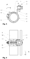
- Fig. 1 to 4 are a first embodiment of the inventive ground terminal 1 in perspective views ( Fig. 1 and 2 ), or a side view ( Fig. 3 ) and a plan view ( Fig. 4 ).
- the ground terminal 1 is shown with a band clamp 5 with lock 13 and strap 14 on a pipe to be grounded 6, wherein the band clamp not tightened.
- the ground terminal 1 has a known clamping device with clamping plate and clamping screw.
- a grounding line 3 is clamped.
- the grounding line 3 may be, for example, a wire, a stranded wire, a rope, a cable or the like.
- the earthing terminal 1 further comprises a fastening section 4 with a contact element designed as a contact plate 7, which rests on the tube 6.
- the contact plate 7 is angled centrally, so that the support surface is enlarged to the tube 6.
- the attachment portion 4 on two opposite sides of the contact plate 7 each about 90 degrees bent parts, in which a slot-shaped recess 8 are formed as a guide means for the band clamp 5.
- the slot-shaped recesses 8 extend beyond the bent region, so that the clamping force of the pipe clamp 5 is transmitted via the clamping band 14 directly to the contact plate 7.
- the bent part is continued as a connecting portion 9 for the clamping device 2.
- the connecting portion 9 is therefore arranged in the running direction of the tension band 14 of the pipe clip 5 on the attachment portion 4.
- the guide means 8 at the free end, ie the clamping device 2, respectively. the connecting portion 9, opposite end, may also be formed as two webs or tongues, between which the pipe clamp 5 can be performed.
- Fig. 3 shows the embodiment in a side view with a view along the longitudinal axis of the tube 6. This illustration clearly shows the enlarged bearing surface of the angled contact plate. 7
- Fig. 5 also shows the embodiment Fig. 1 in a perspective view, wherein the ground terminal 1 is shown detached from the pipe clamp 5 with lock 13 and strap 14.
- a clamp can also be another suitable fastener be used.
- the contact plate 7 also has a predetermined bending point 15. The predetermined bending point 15 is arranged such that when attaching the ground terminal 1 on a pipe to be grounded 5, a portion of the contact plate under the clamping pressure of the pipe clip 5 turns towards the pipe, whereby the contacting of the ground terminal 1 is increased to the tube 5.
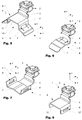
- a second embodiment of the inventive ground terminal 1 is shown in a perspective view.
- the connecting portion 9 opposite side of the contact plate 7 no guide means 8.
- the pipe clamp 5 (not shown) is guided with the clamping band 14 through the slot-shaped recess in the connecting portion 9 and extends over the contact plate. 7
- a third embodiment of the inventive ground terminal 1 is shown in a perspective view.
- the clamping device 2 is connected via a connecting portion 9 with the contact plate 7, wherein the connecting portion 9 arranged transversely to the direction of the pipe clamp on one side of the contact plate, which is between the two guide means 8, 8 '.
- both guide means 8, 8 ' may be formed as webs or tongues.
- a fourth embodiment of the inventive ground terminal 1 is shown in a perspective view.
- the contact element as two connected via a bridge 10 contact plates 7, 7 'is formed.
- Two guide means 8, 8 ' are each formed in bent parts between the contact plates 7, 7' and the bridge 10.
- the pipe clamp 5 (not shown) is with the clamping band through the slot-shaped recess in the bent parts 11, 11 'out, wherein the clamping band 14 under the bridge and over the contact plates 7, 7' extends.
- a fifth embodiment of the inventive ground terminal 1 is shown in a perspective view.
- the contact element as webs 12, 12 'formed directly below the guide means 8, 8'.
Landscapes
- Supports For Pipes And Cables (AREA)
- Clamps And Clips (AREA)
Description
- Die Erfindung betrifft eine Erdungsklemme.
- Erdungsklemmen für die Erdung von z.B. Wasserrohren oder für den Potenzialausgleich sind in verschiedenen Formen auf dem Markt erhältlich. Aus
US2010227483 ist eine Erdungsklemme bekannt, welche aus zwei Halbschalen besteht die über zwei seitliche Flansche miteinander verschraubbar sind. Eine Klemmvorrichtung für die Befestigung eines Erdungsdrahts ist fest auf einem der beiden Halbschalen angeformt. Die Halbschalen stellen den Kontakt zum Rohr her. Zur Montage der Erdungsklemme werden die beiden Halbschalen um das zu erdende Rohr gelegt und mittels Schrauben befestigt. - Aus
DE3502022 undDE3332353 sind weitere Erdungsklemmen bekannt, umfassend eine Klemmvorrichtung, welche seitlich mit einem Befestigungsabschnitt verbunden ist. Ein Metallband ist mit einem Ende fest an dem Befestigungsabschnitt fixiert und kann mit dem freien Ende in ein Führungselement des Befestigungsabschnitts eingesteckt werden. Zur Befestigung der Erdungsklemme an einem zu erdenden Rohr wird das Metallband um das Rohr gelegt und das freie Ende des Metallbands wird in das Führungselement eingesteckt und mittels einer Schraube im Befestigungsabschnitt durch Deformation des Bandes senkrecht zu seiner Oberfläche fixiert. Solche Erdungsklemmen sind umständlich zu montieren und die Art der Fixierung führt zu einer ungenügenden Klemmkraft. Zudem sind sie nicht einfach lös- und wieder verwendbar. -
EP1398850 derselben Anmelderin beschreibt eine Erdungsklemme mit einer Klemmvorrichtung, welche direkt auf einem Tragelement angeordnet ist. Das Tragelement weist zwei seitlich um 90 Grad abgebogene Kontaktelemente auf, welche den Kontakt zur zu erdenden Vorrichtung herstellen. Zudem weist das Tragelement zwei frei stehende, zurückgebogene und quer zu den Kontaktelementen angeordnete Laschen auf, die eine Befestigung der Erdungsklemme mittels einer Bandschelle ermöglichen, aber nicht auf der zu erdenden Vorrichtung aufliegen. Die Erdungsklemme weist viele Hinterschnitte auf, welche eine kostengünstige Herstellung erschweren. Zudem weist sie lange Lastwege zwischen den Laschen und den Kontaktelementen auf und die gesamte Erdungsklemme kann sich bei den hohen Klemmkräften einer Bandschelle ungewollt deformieren, was zu einer ungenügenden Kontaktierung führen kann. - Aufgabe der Erfindung ist es, eine Erdungsklemme anzugeben, welche einfacher und kostengünstiger herstellbar ist und eine bessere Kontaktierung zur zu erdenden Vorrichtung erlaubt.
- Es hat sich nämlich gezeigt, dass die bekannten Erdungsklemmen entweder eine komplizierte Konstruktion aufweisen und daher teuer in der Herstellung sind, oder dass eine sichere Kontaktierungen zur zu erdenden Vorrichtung aufgrund der Anordnung von Kontaktelement, Führungsmittel und Rohrschelle ungenügend sind. Weiterhin ist eine flexible Befestigung nicht möglich.
- Die oben genannte Aufgabe wird durch eine Erdungsklemme mit den Merkmalen des Anspruch 1 gelöst. Die erfindungsgemässe Erdungsklemme, umfassend eine Klemmvorrichtung für mindestens eine Erdungsleitung und einen Befestigungsabschnitt, mit welchem die Erdungsklemme mittels einer geführten Rohrschelle an einer zu erdenden Vorrichtung befestigbar ist, wobei der Befestigungsabschnitt mindestens ein Führungsmittel zur Führung der Rohrschelle aufweist, ist demnach dadurch gekennzeichnet, dass der Befestigungsabschnitt mindestens ein Kontaktelement zur Auflage auf die zu erdende Vorrichtung aufweist, wobei der mindestens eine Führungsabschnitt und das mindestens eine Kontaktelement derart aneinander angrenzend angeordnet sind, dass im montierten Zustand der Erdungsklemme auf einer zu erdenden Vorrichtung das Kontaktelement zwischen der Rohrschelle und der zu erdenden Vorrichtung festgeklemmt und damit fixiert ist. Anstelle einer Rohrschelle kann auch ein anderes geeignetes Befestigungsmittel, wie z.B. eine Bandschelle, Bride, Schlauchschelle, Drahtschelle oder dergleichen, verwendet werden.
- Auf diese Weise ist eine gute und stabile Kontaktierung der Erdungsklemme auf der zu erdenden Vorrichtung gewährleistet, da der Klemmdruck der stark klemmenden Rohrschelle direkt auf das Kontaktelement übertragen wird. Zudem ist aufgrund der einfachen Anordnung von Kontaktelement und Führungsabschnitt und der Befestigung über herkömmliche Rohrschellen eine kostengünstige Herstellung mit wenig Materialverlust möglich. Durch Austausch der Rohrschelle kann die Erdungsklemme z.B. an unterschiedliche Durchmesser angepasst werden.
- Das mindestens eine Kontaktelement der erfindungsgemässen Erdungsklemme ist vorzugsweise eine Kontaktplatte. Dadurch kann die Kontaktfläche der Erdungsklemme wesentlich vergrössert werden, was eine noch bessere Kontaktierung erlaubt. Weiter vorzugsweise kann eine solche Kontaktplatte abgewinkelt oder gerundet ausgebildet sein, und/oder deformierbar sein und/oder eine Sollbiegestelle aufweisen, so dass die Auflagefläche resp. Kontaktfläche der Kontaktplatte auf einer zu erdenden Vorrichtung, vorzugsweise ein Rohr, noch weiter vergrössert ist.
- In einer bevorzugten Ausführungsform ist das mindestens eine Führungsmittel seitlich angrenzend an der mindestens einen Kontaktplatte angeordnet ist.
- In einer weiter bevorzugten Ausführungsform ist jeweils ein Führungsabschnitt an zwei gegenüberliegenden Enden oder Seiten des Kontaktelements angeordnet, so dass im montierten Zustand der Erdungsklemme auf einer zu erdenden Vorrichtung die Rohrschelle über das Kontaktelement verläuft.
- In einer noch weiteren Ausführungsform liegt der mindestens eine Führungsabschnitt zwischen zwei Kontaktelementen, so dass im montierten Zustand der Erdungsklemme auf einer zu erdenden Vorrichtung die Rohrschelle über das Kontaktelement verläuft.
- In den verschiedenen Ausführungsformen kann das mindestens eine Führungsmittel vorzugsweise als Lasche oder schlitzförmige Aussparung ausgebildet sein, durch welche die anzubringende Rohrschelle verläuft. Das mindestens eine Führungsmittel kann auch als zwei Stege oder zwei Zungen ausgebildet sein, so dass die anzubringende Rohrschelle zwischen den Stegen oder Zungen und über dem Kontaktelement verläuft. Die Art der Führungsmittel kann je nach deren Anordnung in den verschiedenen Ausführungsformen gewählt werden.
- In den Ausführungsformen mit Kontaktplatte ist diese bevorzugt abgewinkelt oder gerundet, so dass die Auflagefläche der Kontaktplatte auf einer zu erdenden Vorrichtung, vorzugsweise ein Rohr, vergrössert ist. Das Kontaktelement, vorzugsweise die Kontaktplatte, kann etwa 20 bis 40 mm, vorzugsweise 25 bis 30 mm, breit und etwa 20 bis 40 mm, vorzugsweise 25 bis 30 mm, lang sein.
- Die Klemmvorrichtung kann über einen Verbindungsabschnitt quer zur Laufrichtung der Rohrschelle angeordnet sein. Die Klemmvorrichtung kann auch über einen Verbindungsabschnitt entlang der Laufrichtung der Rohrschelle am Befestigungsabschnitt angeordnet sein, wobei dann mindestens ein Führungsmittel durch eine schlitzförmige Aussparung in dem Verbindungsabschnitt ausgebildet ist.
- Bei allen Ausführungsformen ist der Befestigungsabschnitt und ein Teil der Klemmvorrichtung (ohne z.B. Klemmschraube und Klemmplatte) vorzugsweise zusammen einstückig aus einem Stahlblech gestanzt und/oder gebogen sein. Das Stahlblech kann etwa 1 bis 3 mm, vorzugsweise etwa 2 mm, dick sein.
- Zur Befestigung der Erdungsklemme wird vorzugsweise eine an sich bekannte Bandschelle oder Bride, z.B. mit einem Schraubspannverschluss, verwendet. In allen Ausführungsformen kann eine Rohrschelle mit Schloss und Spannband leicht durch die Führungsmittel angebracht werden. Andere Befestigungsmittel, sofern sie in die Führungsmittel passen, können auch verwendet werden. Die Erdungsklemme ist, solange die Rohrschelle nicht angezogen ist, frei entlang der Rohrschelle verschiebbar, so dass der Verschluss der Rohrschelle und die Klemmvorrichtung in die gewünschten Stellungen gebracht werden können. Der Verschluss resp. das Schloss der Rohrschelle und die Klemmvorrichtung sind also variabel anordbar. Auch ist die erfindungsgemässe Erdungsklemme wiederverwendbar, da die Rohrschelle zerstörungsfrei entfernt werden kann oder schlicht durch eine neue Rohrschelle ersetzt werden kann.
- Die Erfindung betrifft weiter ein Kit aus einer erfindungsgemässen Erdungsklemme und eine Rohrschelle, vorzugsweise eine Bandschelle mit Schloss und Spannband, weiter vorzugsweise eine Bandschelle mit Schraubspannverschluss als Schloss.
- Die Erfindung soll nachfolgend anhand von Ausführungsbeispielen im Zusammenhang mit der Zeichnung näher erläutert werden. Es zeigen:
- Fig. 1
- eine perspektivische Ansicht einer ersten Ausführungsform der erfindungsgemässen Erdungsklemme mit einer Bandschelle auf einem zu erdenden Rohr;
- Fig. 2
- eine weitere perspektivische Ansicht der Ausführungsform aus
Fig. 1 ; - Fig. 3
- eine Seitenansicht der Ausführungsform aus
Fig. 1 ; - Fig. 4
- eine Draufsicht auf die Ausführungsform aus
Fig. 1 ; - Fig. 5
- eine perspektivische Ansicht der Erdungsklemme aus
Fig. 1 losgelöst von der Bandschelle; - Fig. 6
- eine perspektivische Ansicht einer zweiten Ausführungsform der erfindungsgemässen Erdungsklemme;
- Fig. 7
- eine perspektivische Ansicht einer dritten Ausführungsform der erfindungsgemässen Erdungsklemme;
- Fig. 8
- eine perspektivische Ansicht einer vierten Ausführungsform der erfindungsgemässen Erdungsklemme; und
- Fig. 9
- eine perspektivische Ansicht einer fünften Ausführungsform der erfindungsgemässen Erdungsklemme.
- In
Fig. 1 bis 4 sind eine erste Ausführungsform der erfindungsgemässen Erdungsklemme 1 in perspektivischen Ansichten (Fig. 1 und 2 ), bzw. einer Seitenansicht (Fig. 3 ) und einer Draufsicht (Fig. 4 ) gezeigt. Die Erdungsklemme 1 ist mit einer Bandschelle 5 mit Schloss 13 und Spannband 14 auf einem zu erdenden Rohr 6 dargestellt, wobei die Bandschelle nicht festgezogen ist. Die Erdungsklemme 1 weist eine an sich bekannte Klemmvorrichtung mit Klemmplatte und Klemmschraube auf. In der Klemmvorrichtung 2 ist eine Erdungsleitung 3 eingeklemmt. Die Erdungsleitung 3 kann z.B. ein Draht, eine Litze, ein Seil, ein Kabel oder dergleichen sein. Die Erdungsklemme 1 umfasst weiter einen Befestigungsabschnitt 4 mit einem als Kontaktplatte 7 ausgebildetem Kontaktelement, welches auf dem Rohr 6 aufliegt. Die Kontaktplatte 7 ist mittig abgewinkelt, so dass die Auflagefläche auf das Rohr 6 vergrössert ist. Zudem weist der Befestigungsabschnitt 4 auf zwei gegenüberliegenden Seiten der Kontaktplatte 7 jeweils um etwa 90 Grad abgebogene Teile auf, in welche eine schlitzförmige Aussparung 8 als Führungsmittel für die Bandschelle 5 ausgebildet sind. Die schlitzförmigen Aussparungen 8 reichen bis über den abgebogenen Bereich, so dass die Klemmkraft der Rohrschelle 5 über das Spannband 14 direkt auf die Kontaktplatte 7 übertragen wird. - Auf einer der beiden Seiten ist das abgebogene Teil als Verbindungsabschnitt 9 für die Klemmvorrichtung 2 weitergeführt. Der Verbindungsabschnitt 9 ist demnach in Laufrichtung des Spannbands 14 der Rohschelle 5 am Befestigungsabschnitt 4 angeordnet. Das Führungsmittel 8 an dem freien Ende, also dem der Klemmvorrichtung 2, resp. dem Verbindungsabschnitt 9, gegenüberliegenden Ende, kann auch als zwei Stege oder Zungen ausgebildet sein, zwischen welche die Rohrschelle 5 geführt werden kann.
-
Fig. 3 zeigt die Ausführungsform in einer Seitenansicht mit Blick entlang der Längsachse des Rohrs 6. Diese Darstellung zeigt deutlich die vergrösserte Auflagefläche der abgewinkelten Kontaktplatte 7. -
Fig. 5 zeigt ebenfalls die Ausführungsform ausFig. 1 in einer perspektivische Ansicht, wobei die Erdungsklemme 1 von der Rohrschelle 5 mit Schloss 13 und Spannband 14 losgelöst dargestellt ist. Als Rohrschelle kann auch ein anderes geeignetes Befestigungsmittel verwendet werden. Die Kontaktplatte 7 weist zudem eine Sollbiegestelle 15 auf. Die Sollbiegestelle 15 ist derart angeordnet, dass beim Anbringen der Erdungsklemme 1 auf einem zu erdenden Rohr 5 ein Bereich der Kontaktplatte unter dem Klemmdruck der Rohrschelle 5 sich zum Rohr hin abbiegt, wodurch die Kontaktierung der Erdungsklemme 1 zum Rohr 5 erhöht wird. - In
Fig. 6 ist eine zweite Ausführungsform der erfindungsgemässen Erdungsklemme 1 in einer perspektivischen Ansicht dargestellt. Im Unterschied zur Ausführungsform ausFig. 1 ist weist die dem Verbindungsabschnitt 9 gegenüberliegende Seite der Kontaktplatte 7 kein Führungsmittel 8 auf. Die Rohrschelle 5 (nicht dargestellt) wird mit dem Spannband 14 durch die schlitzförmige Aussparung in dem Verbindungsabschnitt 9 geführt und verläuft über die Kontaktplatte 7. - In
Fig. 7 ist eine dritte Ausführungsform der erfindungsgemässen Erdungsklemme 1 in einer perspektivischen Ansicht dargestellt. Im Unterschied zur Ausführungsform ausFig. 1 ist die Klemmvorrichtung 2 über einen Verbindungsabschnitt 9 mit der Kontaktplatte 7 verbunden, wobei der Verbindungsabschnitt 9 quer zur Laufrichtung der Rohrschelle an einer Seite der Kontaktplatte, welche zwischen den beiden Führungsmittel 8, 8' liegt, angeordnet. Bei dieser Ausführungsform können auch beide Führungsmittel 8, 8' als Stege oder Zungen ausgebildet sein. - In
Fig. 8 ist eine vierte Ausführungsform der erfindungsgemässen Erdungsklemme 1 in einer perspektivischen Ansicht dargestellt. Im Unterschied zur Ausführungsform ausFig. 7 ist das Kontaktelement als zwei über eine Brücke 10 verbundene Kontaktplatten 7, 7' ausgebildet. Zwei Führungsmittel 8, 8' sind jeweils in abgebogenen Teilen zwischen den Kontaktplatten 7, 7' und der Brücke 10 ausgebildet. Die Rohrschelle 5 (nicht dargestellt) wird mit dem Spannband durch die schlitzförmige Aussparung in dem abgebogenen Teilen 11, 11' geführt, wobei das Spannband 14 unter der Brücke und über den Kontaktplatten 7, 7' verläuft. - In
Fig. 9 ist eine fünfte Ausführungsform der erfindungsgemässen Erdungsklemme 1 in einer perspektivischen Ansicht dargestellt. Im Unterschied zur Ausführungsform ausFig. 8 sind die Kontaktelement als Stege 12, 12' direkt unterhalb der Führungsmittel 8, 8' ausgebildet. -
- 1
- Erdungsklemme
- 2
- Klemmvorrichtung
- 3
- Erdungsleitung
- 4
- Befestigungsabschnitt
- 5
- Rohrschelle
- 6
- zu erdende Vorrichtung
- 7, 7'
- Kontaktelement, Kontaktplatte
- 8
- Führungsmittel
- 9
- Verbindungsabschnitt
- 10
- Brücke
- 11, 11'
- abgebogener Teil
- 12, 12'
- Kontaktelement, Steg
- 13
- Schloss Rohrschelle
- 14
- Spannband
- 15
- Sollbiegestelle
Claims (15)
- Erdungsklemme (1) umfassend eine Klemmvorrichtung (2) für mindestens eine Erdungsleitung (3) und einen Befestigungsabschnitt (4), mit welchem die Erdungsklemme (1) mittels einer lose geführten Rohrschelle (5) an einer zu erdenden Vorrichtung (6) befestigbar ist, wobei der Befestigungsabschnitt (4) mindestens ein Führungsmittel (8) zur Führung der Rohrschelle (5) aufweist, wobei, der Befestigungsabschnitt (4) mindestens ein Kontaktelement (7) zur Auflage auf die zu erdende Vorrichtung (6) aufweist, dadurch gekennzeichnet, dass das mindestens eine Führungsmittel (8) und das mindestens eine Kontaktelement (7) derart aneinander angrenzend angeordnet sind, dass im montierten Zustand der Erdungsklemme (1) auf einer zu erdenden Vorrichtung (6) das Kontaktelement (7) zwischen der Rohrschelle (5) und der zu erdenden Vorrichtung (6) festgeklemmt ist.
- Erdungsklemme (1) nach Anspruch 1, dadurch gekennzeichnet, dass das mindestens eine Kontaktelement (7) eine Kontaktplatte ist.
- Erdungsklemme (1) nach Anspruch 2, dadurch gekennzeichnet, dass das mindestens eine Führungsmittel (8) seitlich angrenzend an der mindestens einen Kontaktplatte (7) angeordnet ist.
- Erdungsklemme (1) nach Anspruch 2 oder 3, dadurch gekennzeichnet, dass die Kontaktplatte (7) deformierbar ist und/oder eine Sollbiegestelle (15) aufweist, so dass im montierten Zustand der Erdungsklemme (1) auf der zu erdenden Vorrich tung die Kontaktierung der Kontaktplatte (7) auf der zu erdenden Vorrichtung (6) erhöht ist.
- Erdungsklemme (1) nach einem der Ansprüche 1 bis 4, dadurch gekennzeichnet, dass das mindestens ein Führungsmittel (8) als Lasche oder schlitzförmige Aussparung ausgebildet ist.
- Erdungsklemme (1) nach einem der Ansprüche 1 bis 4, dadurch gekennzeichnet, dass das mindestens ein Führungsmittel (8) als zwei Stege oder zwei Zungen ausgebildet ist.
- Erdungsklemme (1) nach einem der Ansprüche 2 bis 6, dadurch gekennzeichnet, dass die Kontaktplatte (7) abgewinkelt oder gerundet ist, so dass die Auflagefläche der Kontaktplatte (7) auf einer zu erdenden Vorrichtung (6), vorzugsweise ein Rohr, vergrössert ist.
- Erdungsklemme (1) nach einem der vorangehenden Ansprüche, dadurch gekennzeichnet, dass das Kontaktelement (7) etwa 20 bis 40 mm, vorzugsweise 25 bis 30 mm, breit und etwa 20 bis 40 mm, vorzugsweise 25 bis 30 mm, lang ist.
- Erdungsklemme nach einem der vorangehenden Ansprüche, dadurch gekennzeichnet, dass jeweils ein Führungsmittel (8) an zwei gegenüberliegenden Seiten des Kontaktelements (7) angeordnet ist, so dass im montierten Zustand der Erdungsklemme (1) auf einer zu erdenden Vorrichtung (6) die Rohrschelle (5) über dem Kontaktelement (7) verläuft.
- Erdungsklemme nach einem der Ansprüche 1 bis 8, dadurch gekennzeichnet, dass das mindestens eine Führungsmittel (8) zwischen zwei Kontaktelementen (7) liegt, so dass im montierten Zustand der Erdungsklemme (1) auf einer zu erdenden Vorrichtung (6) die Rohrschelle (5) über den Kontaktelementen (7) verläuft.
- Erdungsklemme nach einem der vorangehenden Ansprüche, dadurch gekennzeichnet, dass die Klemmvorrichtung (2) über einen Verbindungsabschnitt (9) quer zur Laufrichtung der Rohrschelle (5) angeordnet ist.
- Erdungsklemme nach einem der Ansprüche 1 bis 10, dadurch gekennzeichnet, dass die Klemmvorrichtung (2) über einen Verbindungsabschnitt (9) entlang der Laufrichtung der Rohrschelle (5) am Befestigungsabschnitt (4) angeordnet ist und dass mindestens ein Führungsmittel (8) durch einen schlitzförmige Aussparung in dem Verbindungsabschnitt (9) ausgebildet ist.
- Erdungsklemme nach einem der vorangehenden Ansprüche, dadurch gekennzeichnet, dass der Befestigungsabschnitt (4) zusammen mit einem Teil der Klemmvorrichtung (2) einstückig aus einem Stahlblech gestanzt und/oder gebogen ist.
- Erdungsklemme nach Anspruch 13, dadurch gekennzeichnet, dass das Stahlblech etwa 1 bis 3 mm, vorzugsweise etwa 2 mm, dick ist.
- Kit mit einer Erdungsklemme nach einem der Ansprüche 1 bis 13 und einer Rohrschelle, vorzugsweise eine Bandschelle (5) mit Schloss (13) und Spannband (14).
Applications Claiming Priority (1)
| Application Number | Priority Date | Filing Date | Title |
|---|---|---|---|
| CH12942011A CH705346A2 (de) | 2011-08-04 | 2011-08-04 | Erdungsklemme. |
Publications (2)
| Publication Number | Publication Date |
|---|---|
| EP2555331A1 EP2555331A1 (de) | 2013-02-06 |
| EP2555331B1 true EP2555331B1 (de) | 2016-09-14 |
Family
ID=46650378
Family Applications (1)
| Application Number | Title | Priority Date | Filing Date |
|---|---|---|---|
| EP12177775.9A Active EP2555331B1 (de) | 2011-08-04 | 2012-07-25 | Erdungsklemme |
Country Status (2)
| Country | Link |
|---|---|
| EP (1) | EP2555331B1 (de) |
| CH (1) | CH705346A2 (de) |
Cited By (1)
| Publication number | Priority date | Publication date | Assignee | Title |
|---|---|---|---|---|
| US11649910B2 (en) | 2020-03-06 | 2023-05-16 | Erico International Corporation | Systems and methods for a clamp |
Families Citing this family (2)
| Publication number | Priority date | Publication date | Assignee | Title |
|---|---|---|---|---|
| CH708053A2 (de) * | 2013-05-14 | 2014-11-14 | Agro Ag | Unterputzdose für elektrische Anschlüsse. |
| CH711109B1 (de) * | 2015-05-20 | 2020-03-13 | Agro Ag | Klemmvorrichtung für eine Erdungsklemme und Erdungsklemme. |
Family Cites Families (5)
| Publication number | Priority date | Publication date | Assignee | Title |
|---|---|---|---|---|
| DE3502022A1 (de) | 1983-09-08 | 1986-07-24 | Hermann Kleinhuis GmbH & Co KG, 5880 Lüdenscheid | Erdungsbandschelle mit universalanschlussklemme |
| DE3332353A1 (de) | 1983-09-08 | 1985-03-28 | Hermann Kleinhuis GmbH & Co KG, 5880 Lüdenscheid | Erdungsbandschelle mit universalanschlussklemme |
| US6202300B1 (en) * | 1998-06-05 | 2001-03-20 | Chrysler Corporation | Method for electrical grounding of vehicular components |
| EP1398850B1 (de) | 2002-09-05 | 2005-08-17 | Agro Ag | Erdleitungsbride |
| US7780461B1 (en) | 2009-03-03 | 2010-08-24 | Mike Vernica | Midpoint cable electrical ground clamp |
-
2011
- 2011-08-04 CH CH12942011A patent/CH705346A2/de not_active Application Discontinuation
-
2012
- 2012-07-25 EP EP12177775.9A patent/EP2555331B1/de active Active
Cited By (2)
| Publication number | Priority date | Publication date | Assignee | Title |
|---|---|---|---|---|
| US11649910B2 (en) | 2020-03-06 | 2023-05-16 | Erico International Corporation | Systems and methods for a clamp |
| US12215809B2 (en) | 2020-03-06 | 2025-02-04 | Erico International Corporation | Systems and methods for a clamp |
Also Published As
| Publication number | Publication date |
|---|---|
| CH705346A2 (de) | 2013-02-15 |
| EP2555331A1 (de) | 2013-02-06 |
Similar Documents
| Publication | Publication Date | Title |
|---|---|---|
| EP1133038B1 (de) | Kabelhalter zur Befestigung von Kabeln in Fahrzeugstrukturen | |
| EP1697644A1 (de) | Vorrichtung zum verbinden eines trägerteiles mit einem anbauteil | |
| DE102009057514B3 (de) | Vorrichtung zum Halten und Festklemmen eines Schirmkabels | |
| EP2555331B1 (de) | Erdungsklemme | |
| DE10214966C1 (de) | Schelle zum achsparallelen Verbinden eines zylindrischen Temperaturfühlers mit einem Rohr | |
| DE20319556U1 (de) | Vorrichtung zum Verbinden eines Trägerteiles mit einem Anbauteil | |
| DE20004019U1 (de) | Anschlußelement für Kabelschirme an Montagegestelle, insbesondere Montageschienen | |
| DE102006033800A1 (de) | Kabelbefestigungsvorrichtung und Kabel mit Kabelbefestigungsvorrichtung | |
| DE10035795B4 (de) | Klemmschuhanordnung | |
| DE3204199C2 (de) | Montageblock | |
| DE202011005396U1 (de) | Schlauchschellen für flexible Schläuche | |
| DE102016010951B4 (de) | Klemme mit Kontaktplatte | |
| DE3527677C2 (de) | ||
| EP1182735A2 (de) | Elektrische Reihenklemme | |
| DE202017107378U1 (de) | Montagevorrichtung zur Montage eines Rahmens, beispielsweise für Fenster oder Türen | |
| DE19949509A1 (de) | Schirmklemme zur Anbindung von Kabelschirmen | |
| AT398654B (de) | Vorrichtung zum potentialausgleich | |
| DE102016218306A1 (de) | Einstellbarer Blitzschutz-Fangstangenhalter zur Befestigung an einem Dachfirst und Verwendung des Halters | |
| DE9301520U1 (de) | Vorrichtung zur Befestigung von Installationselementen | |
| DE3812071C2 (de) | Adapter für Klammern und Schellen | |
| DE2735648B2 (de) | Warnkugel zur Befestigung an elektrischen Freileitungen | |
| DE202012101035U1 (de) | Montageelement | |
| EP2333220A2 (de) | Zargenholm, Abstützlasche sowie Verfahren zur Hinterfütterung eines Zargenholms | |
| DE9409822U1 (de) | Vorrichtung zur Sicherung der Stoßverbindung von Kabelkanälen mit U-Profilquerschnitt | |
| DE102007054143A1 (de) | Anschlussvorrichtung und Elektromotor |
Legal Events
| Date | Code | Title | Description |
|---|---|---|---|
| PUAI | Public reference made under article 153(3) epc to a published international application that has entered the european phase |
Free format text: ORIGINAL CODE: 0009012 |
|
| AK | Designated contracting states |
Kind code of ref document: A1 Designated state(s): AL AT BE BG CH CY CZ DE DK EE ES FI FR GB GR HR HU IE IS IT LI LT LU LV MC MK MT NL NO PL PT RO RS SE SI SK SM TR |
|
| AX | Request for extension of the european patent |
Extension state: BA ME |
|
| 17P | Request for examination filed |
Effective date: 20130312 |
|
| GRAP | Despatch of communication of intention to grant a patent |
Free format text: ORIGINAL CODE: EPIDOSNIGR1 |
|
| INTG | Intention to grant announced |
Effective date: 20160309 |
|
| GRAS | Grant fee paid |
Free format text: ORIGINAL CODE: EPIDOSNIGR3 |
|
| GRAA | (expected) grant |
Free format text: ORIGINAL CODE: 0009210 |
|
| AK | Designated contracting states |
Kind code of ref document: B1 Designated state(s): AL AT BE BG CH CY CZ DE DK EE ES FI FR GB GR HR HU IE IS IT LI LT LU LV MC MK MT NL NO PL PT RO RS SE SI SK SM TR |
|
| REG | Reference to a national code |
Ref country code: GB Ref legal event code: FG4D Free format text: NOT ENGLISH |
|
| REG | Reference to a national code |
Ref country code: CH Ref legal event code: EP |
|
| REG | Reference to a national code |
Ref country code: IE Ref legal event code: FG4D Free format text: LANGUAGE OF EP DOCUMENT: GERMAN |
|
| REG | Reference to a national code |
Ref country code: AT Ref legal event code: REF Ref document number: 829901 Country of ref document: AT Kind code of ref document: T Effective date: 20161015 |
|
| REG | Reference to a national code |
Ref country code: DE Ref legal event code: R096 Ref document number: 502012008201 Country of ref document: DE |
|
| REG | Reference to a national code |
Ref country code: CH Ref legal event code: NV Representative=s name: RENTSCH PARTNER AG, CH |
|
| REG | Reference to a national code |
Ref country code: LT Ref legal event code: MG4D |
|
| REG | Reference to a national code |
Ref country code: NL Ref legal event code: MP Effective date: 20160914 |
|
| PG25 | Lapsed in a contracting state [announced via postgrant information from national office to epo] |
Ref country code: LT Free format text: LAPSE BECAUSE OF FAILURE TO SUBMIT A TRANSLATION OF THE DESCRIPTION OR TO PAY THE FEE WITHIN THE PRESCRIBED TIME-LIMIT Effective date: 20160914 Ref country code: RS Free format text: LAPSE BECAUSE OF FAILURE TO SUBMIT A TRANSLATION OF THE DESCRIPTION OR TO PAY THE FEE WITHIN THE PRESCRIBED TIME-LIMIT Effective date: 20160914 Ref country code: NO Free format text: LAPSE BECAUSE OF FAILURE TO SUBMIT A TRANSLATION OF THE DESCRIPTION OR TO PAY THE FEE WITHIN THE PRESCRIBED TIME-LIMIT Effective date: 20161214 Ref country code: FI Free format text: LAPSE BECAUSE OF FAILURE TO SUBMIT A TRANSLATION OF THE DESCRIPTION OR TO PAY THE FEE WITHIN THE PRESCRIBED TIME-LIMIT Effective date: 20160914 Ref country code: HR Free format text: LAPSE BECAUSE OF FAILURE TO SUBMIT A TRANSLATION OF THE DESCRIPTION OR TO PAY THE FEE WITHIN THE PRESCRIBED TIME-LIMIT Effective date: 20160914 |
|
| PG25 | Lapsed in a contracting state [announced via postgrant information from national office to epo] |
Ref country code: LV Free format text: LAPSE BECAUSE OF FAILURE TO SUBMIT A TRANSLATION OF THE DESCRIPTION OR TO PAY THE FEE WITHIN THE PRESCRIBED TIME-LIMIT Effective date: 20160914 Ref country code: SE Free format text: LAPSE BECAUSE OF FAILURE TO SUBMIT A TRANSLATION OF THE DESCRIPTION OR TO PAY THE FEE WITHIN THE PRESCRIBED TIME-LIMIT Effective date: 20160914 Ref country code: NL Free format text: LAPSE BECAUSE OF FAILURE TO SUBMIT A TRANSLATION OF THE DESCRIPTION OR TO PAY THE FEE WITHIN THE PRESCRIBED TIME-LIMIT Effective date: 20160914 Ref country code: GR Free format text: LAPSE BECAUSE OF FAILURE TO SUBMIT A TRANSLATION OF THE DESCRIPTION OR TO PAY THE FEE WITHIN THE PRESCRIBED TIME-LIMIT Effective date: 20161215 |
|
| PG25 | Lapsed in a contracting state [announced via postgrant information from national office to epo] |
Ref country code: EE Free format text: LAPSE BECAUSE OF FAILURE TO SUBMIT A TRANSLATION OF THE DESCRIPTION OR TO PAY THE FEE WITHIN THE PRESCRIBED TIME-LIMIT Effective date: 20160914 Ref country code: RO Free format text: LAPSE BECAUSE OF FAILURE TO SUBMIT A TRANSLATION OF THE DESCRIPTION OR TO PAY THE FEE WITHIN THE PRESCRIBED TIME-LIMIT Effective date: 20160914 |
|
| PG25 | Lapsed in a contracting state [announced via postgrant information from national office to epo] |
Ref country code: PL Free format text: LAPSE BECAUSE OF FAILURE TO SUBMIT A TRANSLATION OF THE DESCRIPTION OR TO PAY THE FEE WITHIN THE PRESCRIBED TIME-LIMIT Effective date: 20160914 Ref country code: IS Free format text: LAPSE BECAUSE OF FAILURE TO SUBMIT A TRANSLATION OF THE DESCRIPTION OR TO PAY THE FEE WITHIN THE PRESCRIBED TIME-LIMIT Effective date: 20170114 Ref country code: SM Free format text: LAPSE BECAUSE OF FAILURE TO SUBMIT A TRANSLATION OF THE DESCRIPTION OR TO PAY THE FEE WITHIN THE PRESCRIBED TIME-LIMIT Effective date: 20160914 Ref country code: CZ Free format text: LAPSE BECAUSE OF FAILURE TO SUBMIT A TRANSLATION OF THE DESCRIPTION OR TO PAY THE FEE WITHIN THE PRESCRIBED TIME-LIMIT Effective date: 20160914 Ref country code: SK Free format text: LAPSE BECAUSE OF FAILURE TO SUBMIT A TRANSLATION OF THE DESCRIPTION OR TO PAY THE FEE WITHIN THE PRESCRIBED TIME-LIMIT Effective date: 20160914 Ref country code: BG Free format text: LAPSE BECAUSE OF FAILURE TO SUBMIT A TRANSLATION OF THE DESCRIPTION OR TO PAY THE FEE WITHIN THE PRESCRIBED TIME-LIMIT Effective date: 20161214 Ref country code: ES Free format text: LAPSE BECAUSE OF FAILURE TO SUBMIT A TRANSLATION OF THE DESCRIPTION OR TO PAY THE FEE WITHIN THE PRESCRIBED TIME-LIMIT Effective date: 20160914 Ref country code: PT Free format text: LAPSE BECAUSE OF FAILURE TO SUBMIT A TRANSLATION OF THE DESCRIPTION OR TO PAY THE FEE WITHIN THE PRESCRIBED TIME-LIMIT Effective date: 20170116 |
|
| REG | Reference to a national code |
Ref country code: DE Ref legal event code: R097 Ref document number: 502012008201 Country of ref document: DE |
|
| PG25 | Lapsed in a contracting state [announced via postgrant information from national office to epo] |
Ref country code: IT Free format text: LAPSE BECAUSE OF FAILURE TO SUBMIT A TRANSLATION OF THE DESCRIPTION OR TO PAY THE FEE WITHIN THE PRESCRIBED TIME-LIMIT Effective date: 20160914 |
|
| PLBE | No opposition filed within time limit |
Free format text: ORIGINAL CODE: 0009261 |
|
| STAA | Information on the status of an ep patent application or granted ep patent |
Free format text: STATUS: NO OPPOSITION FILED WITHIN TIME LIMIT |
|
| PG25 | Lapsed in a contracting state [announced via postgrant information from national office to epo] |
Ref country code: DK Free format text: LAPSE BECAUSE OF FAILURE TO SUBMIT A TRANSLATION OF THE DESCRIPTION OR TO PAY THE FEE WITHIN THE PRESCRIBED TIME-LIMIT Effective date: 20160914 |
|
| 26N | No opposition filed |
Effective date: 20170615 |
|
| REG | Reference to a national code |
Ref country code: CH Ref legal event code: PCAR Free format text: NEW ADDRESS: BELLERIVESTRASSE 203 POSTFACH, 8034 ZUERICH (CH) |
|
| PG25 | Lapsed in a contracting state [announced via postgrant information from national office to epo] |
Ref country code: SI Free format text: LAPSE BECAUSE OF FAILURE TO SUBMIT A TRANSLATION OF THE DESCRIPTION OR TO PAY THE FEE WITHIN THE PRESCRIBED TIME-LIMIT Effective date: 20160914 |
|
| GBPC | Gb: european patent ceased through non-payment of renewal fee |
Effective date: 20170725 |
|
| REG | Reference to a national code |
Ref country code: IE Ref legal event code: MM4A |
|
| REG | Reference to a national code |
Ref country code: FR Ref legal event code: ST Effective date: 20180330 |
|
| PG25 | Lapsed in a contracting state [announced via postgrant information from national office to epo] |
Ref country code: GB Free format text: LAPSE BECAUSE OF NON-PAYMENT OF DUE FEES Effective date: 20170725 Ref country code: IE Free format text: LAPSE BECAUSE OF NON-PAYMENT OF DUE FEES Effective date: 20170725 |
|
| PG25 | Lapsed in a contracting state [announced via postgrant information from national office to epo] |
Ref country code: FR Free format text: LAPSE BECAUSE OF NON-PAYMENT OF DUE FEES Effective date: 20170731 |
|
| REG | Reference to a national code |
Ref country code: BE Ref legal event code: MM Effective date: 20170731 |
|
| PG25 | Lapsed in a contracting state [announced via postgrant information from national office to epo] |
Ref country code: LU Free format text: LAPSE BECAUSE OF NON-PAYMENT OF DUE FEES Effective date: 20170725 |
|
| PG25 | Lapsed in a contracting state [announced via postgrant information from national office to epo] |
Ref country code: BE Free format text: LAPSE BECAUSE OF NON-PAYMENT OF DUE FEES Effective date: 20170731 |
|
| REG | Reference to a national code |
Ref country code: AT Ref legal event code: MM01 Ref document number: 829901 Country of ref document: AT Kind code of ref document: T Effective date: 20170725 |
|
| PG25 | Lapsed in a contracting state [announced via postgrant information from national office to epo] |
Ref country code: MT Free format text: LAPSE BECAUSE OF FAILURE TO SUBMIT A TRANSLATION OF THE DESCRIPTION OR TO PAY THE FEE WITHIN THE PRESCRIBED TIME-LIMIT Effective date: 20160914 |
|
| PG25 | Lapsed in a contracting state [announced via postgrant information from national office to epo] |
Ref country code: AL Free format text: LAPSE BECAUSE OF FAILURE TO SUBMIT A TRANSLATION OF THE DESCRIPTION OR TO PAY THE FEE WITHIN THE PRESCRIBED TIME-LIMIT Effective date: 20160914 |
|
| PG25 | Lapsed in a contracting state [announced via postgrant information from national office to epo] |
Ref country code: AT Free format text: LAPSE BECAUSE OF NON-PAYMENT OF DUE FEES Effective date: 20170725 |
|
| PG25 | Lapsed in a contracting state [announced via postgrant information from national office to epo] |
Ref country code: MC Free format text: LAPSE BECAUSE OF FAILURE TO SUBMIT A TRANSLATION OF THE DESCRIPTION OR TO PAY THE FEE WITHIN THE PRESCRIBED TIME-LIMIT Effective date: 20160914 Ref country code: HU Free format text: LAPSE BECAUSE OF FAILURE TO SUBMIT A TRANSLATION OF THE DESCRIPTION OR TO PAY THE FEE WITHIN THE PRESCRIBED TIME-LIMIT; INVALID AB INITIO Effective date: 20120725 |
|
| PG25 | Lapsed in a contracting state [announced via postgrant information from national office to epo] |
Ref country code: CY Free format text: LAPSE BECAUSE OF NON-PAYMENT OF DUE FEES Effective date: 20160914 |
|
| PG25 | Lapsed in a contracting state [announced via postgrant information from national office to epo] |
Ref country code: MK Free format text: LAPSE BECAUSE OF FAILURE TO SUBMIT A TRANSLATION OF THE DESCRIPTION OR TO PAY THE FEE WITHIN THE PRESCRIBED TIME-LIMIT Effective date: 20160914 |
|
| PG25 | Lapsed in a contracting state [announced via postgrant information from national office to epo] |
Ref country code: TR Free format text: LAPSE BECAUSE OF FAILURE TO SUBMIT A TRANSLATION OF THE DESCRIPTION OR TO PAY THE FEE WITHIN THE PRESCRIBED TIME-LIMIT Effective date: 20160914 |
|
| P01 | Opt-out of the competence of the unified patent court (upc) registered |
Effective date: 20230513 |
|
| PGFP | Annual fee paid to national office [announced via postgrant information from national office to epo] |
Ref country code: DE Payment date: 20240719 Year of fee payment: 13 |
|
| PGFP | Annual fee paid to national office [announced via postgrant information from national office to epo] |
Ref country code: CH Payment date: 20250801 Year of fee payment: 14 |
|
| REG | Reference to a national code |
Ref country code: DE Ref legal event code: R119 Ref document number: 502012008201 Country of ref document: DE |