EP2555890B1 - Verfahren zur herstellung eines zumindest bereichsweise einen erhöhten verschleissschutz aufweisenden gusswerkstücks - Google Patents
Verfahren zur herstellung eines zumindest bereichsweise einen erhöhten verschleissschutz aufweisenden gusswerkstücks Download PDFInfo
- Publication number
- EP2555890B1 EP2555890B1 EP11715656.2A EP11715656A EP2555890B1 EP 2555890 B1 EP2555890 B1 EP 2555890B1 EP 11715656 A EP11715656 A EP 11715656A EP 2555890 B1 EP2555890 B1 EP 2555890B1
- Authority
- EP
- European Patent Office
- Prior art keywords
- ceramic
- insert
- casting
- binding agent
- cast workpiece
- Prior art date
- Legal status (The legal status is an assumption and is not a legal conclusion. Google has not performed a legal analysis and makes no representation as to the accuracy of the status listed.)
- Active
Links
Images
Classifications
-
- B—PERFORMING OPERATIONS; TRANSPORTING
- B22—CASTING; POWDER METALLURGY
- B22D—CASTING OF METALS; CASTING OF OTHER SUBSTANCES BY THE SAME PROCESSES OR DEVICES
- B22D19/00—Casting in, on, or around objects which form part of the product
- B22D19/02—Casting in, on, or around objects which form part of the product for making reinforced articles
-
- B—PERFORMING OPERATIONS; TRANSPORTING
- B22—CASTING; POWDER METALLURGY
- B22D—CASTING OF METALS; CASTING OF OTHER SUBSTANCES BY THE SAME PROCESSES OR DEVICES
- B22D19/00—Casting in, on, or around objects which form part of the product
- B22D19/08—Casting in, on, or around objects which form part of the product for building-up linings or coverings, e.g. of anti-frictional metal
-
- B—PERFORMING OPERATIONS; TRANSPORTING
- B22—CASTING; POWDER METALLURGY
- B22D—CASTING OF METALS; CASTING OF OTHER SUBSTANCES BY THE SAME PROCESSES OR DEVICES
- B22D19/00—Casting in, on, or around objects which form part of the product
- B22D19/14—Casting in, on, or around objects which form part of the product the objects being filamentary or particulate in form
Definitions
- the invention relates to a method for producing a cast workpiece having increased wear protection at least in regions according to the preamble of patent claim 1.
- EP 0 841 990 B1 A method similar to that of the aforementioned type is known from EP 0 841 990 B1 known.
- a perforated or sponge-like ceramic insert is used, which penetrates during the casting of the casting material into the openings and pores of the insert. It is not easy in this process, inexpensive to produce deposits with the desired layer thickness and the desired shape.
- EP 0 670 441 A1 is a method of the type mentioned became known, which describes the production of plain bearings, on the one hand closure and on the other hand are low in friction.
- a molded body made of hard material is encapsulated with open cavities such that the cavities are infiltrated with light metal.
- the shaped body may optionally be applied to a substrate. Instructions on how to proceed with cast workpieces with other surface geometries to be protected against wear are the EP 0 670 441 A1 not to be taken.
- Object of the present invention is to provide a method of the type mentioned in such a way that the shape of the insert is well adapted to the shape of the workpiece surface to be protected.
- a two-layered structure is first produced, which, as it were, has as carrier a heat-resistant fiber mat to which the ceramic particles bound in the binder are applied.
- the thickness of the ceramic particle layer can be determined very well in this way.
- the ceramic particles have an average particle size between 0.2 and 4 mm.
- the lower limit of the mean grain size is essentially determined by the fact that the infiltration capacity of the ceramic-containing layer must not be called into question.
- the upper limit of the mean particle size results from the fact that a sufficient coverage density must be ensured in order to achieve the desired wear resistance.
- the insert 9 is inserted into a conventional mold 10, as shown in FIG FIG. 1 is shown.
- This casting mold 10 comprises a top box 6 with pouring basin 3 and pouring channel 4 and feeder 5.
- the casting cavity 8 corresponding to the shape of the desired workpiece is formed.
- the insert 9 is fixed at the point of the wall of the casting cavity 8, which corresponds to the surface to be protected of the workpiece to be produced.
- this can for example be done by nailing.
- the workpiece is poured off in a known manner with metallic material.
- the liquid metallic material encloses the Kermaikpgreg in the layer 1 of the insert 2, wherein the binder substantially evaporates.
- the workpiece is now on the surface to be protected with a ceramic particle layer provided, which there is an increased wear resistance is achieved.
- the fact that the removed from the mold 10 workpiece in that area in which the insert 9 is located, the layer 2 of fiberglass mat, is harmless because it is quickly abraded in the use of the workpiece.
Landscapes
- Engineering & Computer Science (AREA)
- Mechanical Engineering (AREA)
- Laminated Bodies (AREA)
- Mold Materials And Core Materials (AREA)
- Manufacture Of Alloys Or Alloy Compounds (AREA)
- Moulds For Moulding Plastics Or The Like (AREA)
Description
- Die Erfindung betrifft ein Verfahren zur Herstellung eines zumindest bereichsweise einen erhöhten Verschleißschutz aufweisenden Gusswerkstücks nach dem Oberbegriff des Patentanspruchs 1.
- Es ist ein seit langem bekanntes Problem, dass duktile Gusswerkstücke zwar hohe Schlagbeständigkeit und Zähigkeit aufweisen, jedoch nur geringe Widerstandsfähigkeit gegen Verschleiß besitzen. Umgekehrt sind sehr verschleißbeständige Werkstücke im Allgemeinen spröde und halten Schlagbeanspruchungen nicht stand. Daher sind schon viele Versuche unternommen worden, Verbundwerkstücke herzustellen, bei denen in eine duktile, schlagbeständige Matrix verschleißbeständige Einlagen aus Hartmaterial eingebettet sind.
- Ein Verfahren ähnlich dem der eingangs genannten Art ist aus der
EP 0 841 990 B1 bekannt. Hier wird eine perforierte oder schwammartig ausgebildete Keramik-Einlage verwendet, wodurch beim Gießvorgang der Gießwerkstoff in die Öffnungen und Poren der Einlage eindringt. Es ist bei diesem Verfahren nicht ganz einfach, Einlagen mit der gewünschten Schichtdicke und der gewünschten Form preiswert herzustellen. - Aus der
EP 0 670 441 A1 ist ein Verfahren der eingangs genannten Art bekannt geworden, welches die Herstellung von Gleitlagern beschreibt, die einerseits verschließarm und andererseits reibungsarm sind. Dabei wird ein aus Hartstoff hergestellter Formkörper mit offenen Hohlräumen derart umgossen, dass die Hohlräume mit Leichtmetall infiltriert werden. Der Formkörper kann gegebenenfalls auf einem Substrat aufgebracht sein. Hinweise, wie bei Gusswerkstücken mit anderen gegen Verschleiß zu schützenden Oberflächengeometrien vorgegangen werden kann, sind derEP 0 670 441 A1 nicht zu entnehmen. - Aufgabe der vorliegenden Erfindung ist es, ein Verfahren der eingangs genannten Art derart auszubilden, dass die Form der Einlage an die Form der zu schützenden Werkstückoberfläche gut anpassbar ist.
- Diese Aufgabe wird erfindungsgemäß durch ein im Patentanspruch 1 angegebenes Verfahren gelöst.
- Wie im Stand der Technik an sich bekannt, wird zunächst eine zweischichtige Struktur hergestellt, die gewissermaßen als Träger eine hitzebeständige Fasermatte besitzt, auf welche die in Bindemittel gebundenen Keramikpartikel aufgebracht sind. Die Dicke der Keramikpartikel-Schicht kann auf diese Weise sehr gut bestimmt werden.
- Erfindungsgemäß weisen die Keramikpartikel eine mittlere Korngröße zwischen 0,2 und 4 mm auf. Die Untergrenze der mittleren Korngröße wird im Wesentlichen dadurch bestimmt, dass die Infiltrationsfähigkeit der Keramikhaltigen Schicht nicht in Frage gestellt werden darf. Die Obergrenze der mittleren Partikelgröße ergibt sich daraus, dass eine ausreichende Bedeckungsdichte gewährleistet sein muss, um die gewünschte Verschleißbeständigkeit zu erzielen.
- Durch Konfektionieren dieser zweischichtigen Struktur kann dann exakt diejenige Form hergestellt werden, die der Form des zu schützenden Oberflächenbereiches des Werkstückes (ggfs in eine Ebene abgewickelt) entspricht. Das Bindemittel entweicht im Allgemeinen beim Gießvorgang, während die Fasermatte als am Werkstück nach außen zeigende Schicht verbleiben kann. Diese wird im Gebrauch des Gusswerkstückes schnell verschlissen oder kann bei Bedarf auch vor dem Einsatz des Gusswerkstückes entfernt werden.
- Besonders bevorzugt wird, wenn die mittlere Korngröße der Keramikpartikel 1 bis 2 mm beträgt.
- Als Keramikmaterial kann insbesondere Zirkonoxid- oder Aluminiumoxid-Keramik eingesetzt werden. Derartige Partikel werden in der Schleifmittelindustrie eingesetzt und sind kommerziell preiswert erhältlich.
- Als Bindemittel kann Wasserglas verwendet werden, das ebenfalls ein kostengünstiger und leicht handzuhabender Werkstoff ist.
- Vorzugsweise wird als ausschließliches oder zusätzliches Bindemittel eine die Flexibilität der Einlage erhaltende Schlichte eingesetzt. Hierfür eignen sich beispielsweise Schlichten, wie sie bisher zur Versiegelung von schlecht ausgeschäumten Modellbereichen oder auch geschnittenen oder gefrästen Oberflächen eingesetzt werden. Eine derartige Schlichte ist unter dem Markennamen "Polyfiller S" von der Firma Ashland-Südchemie Kernfest GmbH, D-40721 Hilden, erhältlich.
- Der Giesswerkstoff kann sowohl metallisch, also insbesondere Stahl, ein Buntmetall oder Aluminium, als auch ein Kunststoff sein.
- Als Fasermatte kann grundsätzlich jedes "offenporige" textilartige Material eingesetzt weden, sofern nur die Hitzebeständigkeit gewährleistet ist. Bevorzugt werden Glasfasermatten. Es sind jedoch auch Matten aus entsprechendem Kunststoff denkbar.
- Die Dicke der keramikhaltigen Schicht auf der Fasermatte sollte zwischen 3 und 8 mm liegen.
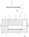
- Ein Ausführungsbeispiel der Erfindung wird nachfolgend anhand der Zeichnung näher erläutert; es zeigen:
- Figur 1
- einen Schnitt durch eine Einlage, wie sie beim erfindungsgemäßen Verfahren Verwendung findet;
- Figur 2
- einen schematischen Schnitt durch eine Gießform, in welche die Einlage der
Figur 1 eingelegt ist. - Die Zeichnung zeigt, wie bei der Herstellung eines an einer Oberfläche vor Verschleiß zu schützenden Gegenstandes beispielhaft vorgegangen werden kann:
- Zunächst werden Keramikpartikel, beispielsweise 40-prozentiges Zirkonkorund mit einer mittleren Korngröße zwischen 1 und 2 mm, mit 3-prozentigem Wasserglas und/ oder 3-prozentiger Schlichte "Polyfiller S" als Bindemittel vermischt. Diese Masse wird in einer Schicht 1 gewünschter Dicke auf eine Glasfasermatte 2 aufgebracht. Die mit Keramikpartikeln beschichtete Glasfasermatte 2 hat eine Dicke von 6 bis 8 Millimetern. Nach dem Aushärten des Bindemittels wird die so entstandene zweischichtige mattenartige Struktur konfektioniert. Es entsteht so die in
Figur 1 dargestellte zweischichtige Einlage 9, die exakt an die Form der zu schützenden Oberfläche des Werkstückes angepasst ist. Aufgrund der oben erwähnten Schlichte wird die Einlage 9 nicht starr, sondern bleibt in gewissem Umfange flexibel, so dass sie gegebenenfalls auch gebogen werden kann. - Die Einlage 9 wird in eine herkömmliche Gießform 10 eingelegt, wie dies in
Figur 1 gezeigt ist. Diese Gießform 10 umfasst einen Oberkasten 6 mit Eingusstümpel 3 und Eingusskanal 4 sowie Speiser 5. Im Unterkasten 7 sowie teilweise auch im Oberkasten 6 ist der der Form des gewünschten Werkstückes entsprechende Gießhohlraum 8 ausgebildet. - Die Einlage 9 wird an derjenigen Stelle der Wandung des Gießhohlraumes 8 befestigt, welche der zu schützenden Oberfläche des herzustellenden Werkstückes entspricht. Bei Verwendung einer Sandform kann dies beispielsweise durch Nageln geschehen. Nach Schließen der Gießform 10 wird das Werkstück in bekannter Weise mit metallischem Werkstoff abgegossen. Der flüssige metallische Werkstoff umschließt die Kermaikpartikel in der Schicht 1 der Einlage 2, wobei das Bindemittel im Wesentlichen verdampft. Das Werkstück ist nun an der zu schützenden Oberfläche mit einer Keramikpartikel-Schicht versehen, wodurch dort eine erhöhte Verschleissbeständigkeit erzielt wird. Dass das aus der Gießform 10 entnommene Werkstück in demjenigen Bereich, in dem sich die Einlage 9 befindet, die Schicht 2 aus Glasfasermatte besitzt, ist unschädlich, da diese im Gebrauch des Werkstückes rasch abgeschliffen wird.
Claims (9)
- Verfahren zur Herstellung eines zumindest bereichsweise einen erhöhten Verschleißschutz aufweisenden Gusswerkstückes, bei dem keramikhaltiges Material beim Gießen in die Matrix des Gießwerkstoffes eingebettet wird;
wobeia) Keramikpartikel mit einer mittleren Korngröße zwischen 0,2 und 4 mm mit mindestens einem Bindemittel vermischt werden;b) die Mischung aus Keramikpartikeln und Bindemittel in einer bestimmten Schichtdicke auf eine hitzebeständige Fasermatte aufgebracht wird, wodurch eine zweischichtige Struktur entsteht;c) nach dem Abbinden des Bindemittels aus der zweischichtigen Struktur eine Einlage (9) konfektioniert wird, deren Form der Form eines zu schützenden Oberflächenbereiches des Gusswerkstückes entspricht;d) die Einlage (9) in dem Gießhohlraum (8) an derjenigen Stelle angebracht wird, die dem zu schützenden Oberflächenbereich des Gusswerkstückes entspricht;e) der Gießhohlraum (8) mit dem Gießwerkstoff ausgegossen wird, wobei die Keramikpartikel in der Einlage (9) in dem Gießwerkstoff eingebettet werden. - Verfahren nach Anspruch 1, dadurch gekennzeichnet, dass die mittlere Korngröße der Keramikpartikel 1 bis 2 mm beträgt.
- Verfahren nach Anspruch 1 oder 2, dadurch gekennzeichnet, dass als Keramikmaterial Zirkonoxid- oder Aluminiumoxid-Keramik eingesetzt wird.
- Verfahren nach einem der vorhergehenden Ansprüche, dadurch gekennzeichnet, dass als Bindemittel Wasserglas eingesetzt wird.
- Verfahren nach einem der vorhergehenden Ansprüche, dadurch gekennzeichnet, dass als ausschließliches oder zusätzliches Bindemittel eine die Flexibilität der Einlage (9) erhaltende Schlichte eingesetzt wird.
- Verfahren nach einem der vorhergehenden Ansprüche, dadurch gekennzeichnet, dass der Gießwerkstoff metallisch, insbesondere Stahl, oder ein Buntmetall oder Aluminium ist.
- Verfahren nach einem der Ansprüche 1 bis 5, dadurch gekennzeichnet, dass der Gießwerkstoff ein Kunststoff ist.
- Verfahren nach einem der vorhergehenden Ansprüche, dadurch gekennzeichnet, dass die Fasermatte (2) aus Glasfasern besteht.
- Verfahren nach einem der vorhergehenden Ansprüche, dadurch gekennzeichnet, dass die keramikhaltige Schicht auf der Fasermatte ein Dicke zwischen 3 und 8 mm besitzt.
Applications Claiming Priority (2)
| Application Number | Priority Date | Filing Date | Title |
|---|---|---|---|
| DE102010013999A DE102010013999A1 (de) | 2010-04-07 | 2010-04-07 | Verfahren zur Herstellung eines zumindest bereichsweise einen erhöhten Verschleißschutz aufweisenden Gusswerkstücks |
| PCT/EP2011/001568 WO2011124345A1 (de) | 2010-04-07 | 2011-03-29 | Verfahren zur herstellung eines zumindest bereichsweise einen erhöhten verschleissschutz aufweisenden gusswerkstücks |
Publications (2)
| Publication Number | Publication Date |
|---|---|
| EP2555890A1 EP2555890A1 (de) | 2013-02-13 |
| EP2555890B1 true EP2555890B1 (de) | 2018-02-28 |
Family
ID=44144893
Family Applications (1)
| Application Number | Title | Priority Date | Filing Date |
|---|---|---|---|
| EP11715656.2A Active EP2555890B1 (de) | 2010-04-07 | 2011-03-29 | Verfahren zur herstellung eines zumindest bereichsweise einen erhöhten verschleissschutz aufweisenden gusswerkstücks |
Country Status (6)
| Country | Link |
|---|---|
| US (1) | US20130056139A1 (de) |
| EP (1) | EP2555890B1 (de) |
| CN (1) | CN102869466A (de) |
| DE (1) | DE102010013999A1 (de) |
| PT (1) | PT2555890T (de) |
| WO (1) | WO2011124345A1 (de) |
Families Citing this family (6)
| Publication number | Priority date | Publication date | Assignee | Title |
|---|---|---|---|---|
| DE102013200680B4 (de) * | 2012-01-19 | 2017-08-03 | Ksb Aktiengesellschaft | Verfahren zur Herstellung eines mit einer Verschleißschutzschicht versehenen Bauteils sowie eine Vorrichtung zur Durchführung des Verfahrens |
| DE102012204614A1 (de) * | 2012-03-22 | 2013-09-26 | Man Diesel & Turbo Se | Verfahren zum Herstellen eines Gussteils und nach dem Verfahren hergestelltes Gussteil |
| WO2015103670A1 (en) * | 2014-01-09 | 2015-07-16 | Bradken Uk Limited | Wear member incorporating wear resistant particles and method of making same |
| US11801621B2 (en) * | 2020-05-29 | 2023-10-31 | The Boeing Company | System and method for curing thermoset composites |
| CN113523244B (zh) * | 2021-07-09 | 2022-04-01 | 邯郸慧桥复合材料科技有限公司 | 一种可焊双金属耐磨件固液复合铸造方法 |
| CN116422865A (zh) * | 2023-03-16 | 2023-07-14 | 南通理工学院 | 一种陶瓷颗粒增强高铬铸铁基复合衬板的铸造工艺 |
Family Cites Families (27)
| Publication number | Priority date | Publication date | Assignee | Title |
|---|---|---|---|---|
| DD70969A (de) * | ||||
| DE2335588C3 (de) * | 1973-07-13 | 1977-04-21 | Wahl Verschleiss Tech | Verfahren zum herstellen metallischer verbundgusstuecke |
| CH582574A5 (de) * | 1973-07-13 | 1976-12-15 | Wahl Hans Dr Ing Verschleiss T | |
| DE2960516D1 (en) * | 1978-01-31 | 1981-10-29 | Atomic Energy Authority Uk | Thermally insulating, fire resistant material and its production |
| US4481124A (en) * | 1983-01-07 | 1984-11-06 | Ngk Insulators, Ltd. | Thermal shock resistant porous sound absorbing body |
| DE3530924A1 (de) * | 1985-08-29 | 1987-03-12 | Alcan Aluminiumwerke | Hitzebestaendiges bauteil und verfahren zu dessen herstellung |
| EP0280830A1 (de) * | 1987-03-02 | 1988-09-07 | Battelle Memorial Institute | Verfahren zur Herstellung von faser- oder teilchenverstärkten, gegossenen Metallverbundwerkstoffen oder Metallegierungsverbundwerkstoffen |
| US4785522A (en) * | 1987-09-04 | 1988-11-22 | Biro Manufacturing Company | Method of making a band saw wheel |
| US5027878A (en) * | 1989-10-05 | 1991-07-02 | Deere & Company | Method of impregnation of iron with a wear resistant material |
| DE4009714A1 (de) * | 1990-03-27 | 1991-10-02 | Kolbenschmidt Ag | Einzelzylinder bzw. mehrzylinderblock |
| US5288353A (en) * | 1992-01-21 | 1994-02-22 | Deere & Company | Method for forming a polymeric plastic product having a hard wear-resistant surface |
| US5267600A (en) * | 1992-01-21 | 1993-12-07 | Deere & Company | Hard facing casting surfaces with wear-resistant sheets |
| DE4310698A1 (de) * | 1992-04-16 | 1993-10-21 | Volkswagen Ag | Verfahren zur Herstellung eines Maschinengehäuses |
| US5511603A (en) * | 1993-03-26 | 1996-04-30 | Chesapeake Composites Corporation | Machinable metal-matrix composite and liquid metal infiltration process for making same |
| US5322109A (en) * | 1993-05-10 | 1994-06-21 | Massachusetts Institute Of Technology, A Massachusetts Corp. | Method for pressure infiltration casting using a vent tube |
| DE4406191A1 (de) * | 1994-02-25 | 1995-09-07 | Ks Aluminium Technologie Ag | Gleitlagerung |
| EP0739668A2 (de) * | 1995-04-26 | 1996-10-30 | Ryobi Ltd. | Zylinderblock und Zylinderbuchse und Verfahren zur deren Herstellung |
| DE19528512C2 (de) | 1995-08-03 | 2001-02-22 | Swb Stahlformgusgmbh | Verschleißteile und Verfahren zu deren Herstellung |
| CN1128297A (zh) * | 1995-11-20 | 1996-08-07 | 西安交通大学 | 一种局部复合材料及其制造方法 |
| JP4049814B2 (ja) * | 1995-11-27 | 2008-02-20 | チェサピーク コンポジッツ コーポレーション | 機械加工可能な金属マトリックス複合体及び液体金属浸透方法 |
| JPH10314912A (ja) * | 1997-05-16 | 1998-12-02 | Honda Motor Co Ltd | ダイカスト法による繊維強化金属体鋳造用繊維成形体 |
| US6352385B1 (en) * | 2000-07-31 | 2002-03-05 | General Electric Company | Mechanical coupling for cooperating rotatable members |
| JP2003191066A (ja) * | 2001-12-25 | 2003-07-08 | Yazaki Corp | 複合材及びその製造方法 |
| DE10303351B3 (de) * | 2003-01-29 | 2004-09-23 | Daimlerchrysler Ag | Bauteil aus Metall/Keramik-Verbundwerkstoff mit intermetallischer Matrix, dessen Verwendung als Panzermaterial und Verfahren zu dessen Herstellung |
| DE102004005458B4 (de) * | 2004-02-04 | 2006-05-11 | Ks Aluminium-Technologie Ag | Zylinderblock für eine Brennkraftmaschine und Verfahren zur Herstellung eines Zylinderblocks |
| CN101112718B (zh) * | 2007-08-28 | 2010-07-28 | 暨南大学 | 陶瓷颗粒增强铁基复合材料及其制备方法 |
| DE102011115024A1 (de) * | 2011-10-07 | 2013-04-11 | Ask Chemicals Gmbh | Beschichtungsmassen für anorganische Gießformen und Kerne umfassend Ameisensäureester und deren Verwendung |
-
2010
- 2010-04-07 DE DE102010013999A patent/DE102010013999A1/de not_active Withdrawn
-
2011
- 2011-03-29 PT PT117156562T patent/PT2555890T/pt unknown
- 2011-03-29 WO PCT/EP2011/001568 patent/WO2011124345A1/de not_active Ceased
- 2011-03-29 CN CN2011800168045A patent/CN102869466A/zh active Pending
- 2011-03-29 US US13/639,256 patent/US20130056139A1/en not_active Abandoned
- 2011-03-29 EP EP11715656.2A patent/EP2555890B1/de active Active
Also Published As
| Publication number | Publication date |
|---|---|
| WO2011124345A1 (de) | 2011-10-13 |
| US20130056139A1 (en) | 2013-03-07 |
| DE102010013999A1 (de) | 2011-10-13 |
| EP2555890A1 (de) | 2013-02-13 |
| CN102869466A (zh) | 2013-01-09 |
| PT2555890T (pt) | 2018-04-17 |
Similar Documents
| Publication | Publication Date | Title |
|---|---|---|
| EP2555890B1 (de) | Verfahren zur herstellung eines zumindest bereichsweise einen erhöhten verschleissschutz aufweisenden gusswerkstücks | |
| DE102008052697A1 (de) | Einsätze mit Öffnungen für gedämpfte Produkte und Verfahren zur Herstellung sowie deren Verwendung | |
| DE102013200680B4 (de) | Verfahren zur Herstellung eines mit einer Verschleißschutzschicht versehenen Bauteils sowie eine Vorrichtung zur Durchführung des Verfahrens | |
| EP2069707B1 (de) | Metallformkörper und Verfahren zur Herstellung eines Metallformkörpers | |
| DE10261116B4 (de) | Verbundwerkstoff und Verfahren zur Herstellung desselben | |
| DE4112000A1 (de) | Verfahren zur herstellung von verschleissgeschuetzten gussstuecken | |
| DE102009052279A1 (de) | Kohlenstoffhaltiges feuerfestes Material zur Verwendung beim Vergießen von Stahl im Untergussverfahren und daraus hergestellte Formkörper | |
| DE2335588B2 (de) | Verfahren zum herstellen metallischer verbundgusstuecke | |
| DE3724995C2 (de) | ||
| DE102008032271B4 (de) | Verfahren zur Herstellung eines Verbundmaterials | |
| WO2000032335A1 (de) | Verbundgussteil und verfahren zu seiner herstellung | |
| DE10026290B4 (de) | Zylinderkurbelgehäuse für eine Brennkraftmaschine | |
| EP1900961A2 (de) | Bremsscheibe und Verfahren zur Herstellung der Bremsscheibe | |
| DE102005009669A1 (de) | Giesskammer | |
| DE10350725A1 (de) | Belagträgerplatte und Verfahren zu deren Herstellung | |
| EP2312063B1 (de) | Abdeckung mit verschleißfester Oberfläche sowie Verfahren zu deren Herstellung | |
| EP1105236B1 (de) | Giesswerkzeug für das giessen von formteilen aus nicht-eisenmetallen | |
| EP0007664A1 (de) | Verfahren zum Beschichten und Löten von Werkstücken mit Hartmetall-Legierungen | |
| DE10122886B4 (de) | Bearbeitungskörper mit eingegossenem Hartstoffkörper zum Zerkleinern eines Aufgabeguts | |
| DE202009012778U1 (de) | Verbundbremsklotzsohle und Verbundbremsklotz | |
| EP3960329A1 (de) | Giesstechnisches bauteil mit korrosionsschutzschichtaufbau | |
| DE102004012990A1 (de) | Verbundwerkstoff, Verfahren zur Herstellung eines derartigen Verbundwerkstoffes sowie dessen Verwendung | |
| DE8418690U1 (de) | Brechkern für Speiser von Aluminium-Gußstücken | |
| EP1797976A2 (de) | Spülkegel | |
| DE4332744A1 (de) | Verfahren zum Gießen von Formteilen |
Legal Events
| Date | Code | Title | Description |
|---|---|---|---|
| PUAI | Public reference made under article 153(3) epc to a published international application that has entered the european phase |
Free format text: ORIGINAL CODE: 0009012 |
|
| 17P | Request for examination filed |
Effective date: 20120913 |
|
| AK | Designated contracting states |
Kind code of ref document: A1 Designated state(s): AL AT BE BG CH CY CZ DE DK EE ES FI FR GB GR HR HU IE IS IT LI LT LU LV MC MK MT NL NO PL PT RO RS SE SI SK SM TR |
|
| DAX | Request for extension of the european patent (deleted) | ||
| STAA | Information on the status of an ep patent application or granted ep patent |
Free format text: STATUS: EXAMINATION IS IN PROGRESS |
|
| GRAJ | Information related to disapproval of communication of intention to grant by the applicant or resumption of examination proceedings by the epo deleted |
Free format text: ORIGINAL CODE: EPIDOSDIGR1 |
|
| GRAP | Despatch of communication of intention to grant a patent |
Free format text: ORIGINAL CODE: EPIDOSNIGR1 |
|
| GRAP | Despatch of communication of intention to grant a patent |
Free format text: ORIGINAL CODE: EPIDOSNIGR1 |
|
| STAA | Information on the status of an ep patent application or granted ep patent |
Free format text: STATUS: GRANT OF PATENT IS INTENDED |
|
| INTG | Intention to grant announced |
Effective date: 20170913 |
|
| GRAS | Grant fee paid |
Free format text: ORIGINAL CODE: EPIDOSNIGR3 |
|
| GRAA | (expected) grant |
Free format text: ORIGINAL CODE: 0009210 |
|
| STAA | Information on the status of an ep patent application or granted ep patent |
Free format text: STATUS: THE PATENT HAS BEEN GRANTED |
|
| AK | Designated contracting states |
Kind code of ref document: B1 Designated state(s): AL AT BE BG CH CY CZ DE DK EE ES FI FR GB GR HR HU IE IS IT LI LT LU LV MC MK MT NL NO PL PT RO RS SE SI SK SM TR |
|
| REG | Reference to a national code |
Ref country code: GB Ref legal event code: FG4D Free format text: NOT ENGLISH Ref country code: CH Ref legal event code: EP |
|
| REG | Reference to a national code |
Ref country code: AT Ref legal event code: REF Ref document number: 973569 Country of ref document: AT Kind code of ref document: T Effective date: 20180315 |
|
| REG | Reference to a national code |
Ref country code: IE Ref legal event code: FG4D Free format text: LANGUAGE OF EP DOCUMENT: GERMAN |
|
| REG | Reference to a national code |
Ref country code: DE Ref legal event code: R096 Ref document number: 502011013817 Country of ref document: DE |
|
| REG | Reference to a national code |
Ref country code: FR Ref legal event code: PLFP Year of fee payment: 8 |
|
| REG | Reference to a national code |
Ref country code: PT Ref legal event code: SC4A Ref document number: 2555890 Country of ref document: PT Date of ref document: 20180417 Kind code of ref document: T Free format text: AVAILABILITY OF NATIONAL TRANSLATION Effective date: 20180411 |
|
| REG | Reference to a national code |
Ref country code: SE Ref legal event code: TRGR |
|
| REG | Reference to a national code |
Ref country code: NL Ref legal event code: MP Effective date: 20180228 |
|
| REG | Reference to a national code |
Ref country code: LT Ref legal event code: MG4D |
|
| PG25 | Lapsed in a contracting state [announced via postgrant information from national office to epo] |
Ref country code: ES Free format text: LAPSE BECAUSE OF FAILURE TO SUBMIT A TRANSLATION OF THE DESCRIPTION OR TO PAY THE FEE WITHIN THE PRESCRIBED TIME-LIMIT Effective date: 20180228 Ref country code: NL Free format text: LAPSE BECAUSE OF FAILURE TO SUBMIT A TRANSLATION OF THE DESCRIPTION OR TO PAY THE FEE WITHIN THE PRESCRIBED TIME-LIMIT Effective date: 20180228 Ref country code: LT Free format text: LAPSE BECAUSE OF FAILURE TO SUBMIT A TRANSLATION OF THE DESCRIPTION OR TO PAY THE FEE WITHIN THE PRESCRIBED TIME-LIMIT Effective date: 20180228 Ref country code: HR Free format text: LAPSE BECAUSE OF FAILURE TO SUBMIT A TRANSLATION OF THE DESCRIPTION OR TO PAY THE FEE WITHIN THE PRESCRIBED TIME-LIMIT Effective date: 20180228 Ref country code: CY Free format text: LAPSE BECAUSE OF FAILURE TO SUBMIT A TRANSLATION OF THE DESCRIPTION OR TO PAY THE FEE WITHIN THE PRESCRIBED TIME-LIMIT Effective date: 20180228 Ref country code: NO Free format text: LAPSE BECAUSE OF FAILURE TO SUBMIT A TRANSLATION OF THE DESCRIPTION OR TO PAY THE FEE WITHIN THE PRESCRIBED TIME-LIMIT Effective date: 20180528 Ref country code: FI Free format text: LAPSE BECAUSE OF FAILURE TO SUBMIT A TRANSLATION OF THE DESCRIPTION OR TO PAY THE FEE WITHIN THE PRESCRIBED TIME-LIMIT Effective date: 20180228 |
|
| PG25 | Lapsed in a contracting state [announced via postgrant information from national office to epo] |
Ref country code: GR Free format text: LAPSE BECAUSE OF FAILURE TO SUBMIT A TRANSLATION OF THE DESCRIPTION OR TO PAY THE FEE WITHIN THE PRESCRIBED TIME-LIMIT Effective date: 20180529 Ref country code: LV Free format text: LAPSE BECAUSE OF FAILURE TO SUBMIT A TRANSLATION OF THE DESCRIPTION OR TO PAY THE FEE WITHIN THE PRESCRIBED TIME-LIMIT Effective date: 20180228 Ref country code: BG Free format text: LAPSE BECAUSE OF FAILURE TO SUBMIT A TRANSLATION OF THE DESCRIPTION OR TO PAY THE FEE WITHIN THE PRESCRIBED TIME-LIMIT Effective date: 20180528 Ref country code: RS Free format text: LAPSE BECAUSE OF FAILURE TO SUBMIT A TRANSLATION OF THE DESCRIPTION OR TO PAY THE FEE WITHIN THE PRESCRIBED TIME-LIMIT Effective date: 20180228 |
|
| PG25 | Lapsed in a contracting state [announced via postgrant information from national office to epo] |
Ref country code: MT Free format text: LAPSE BECAUSE OF FAILURE TO SUBMIT A TRANSLATION OF THE DESCRIPTION OR TO PAY THE FEE WITHIN THE PRESCRIBED TIME-LIMIT Effective date: 20180228 |
|
| PG25 | Lapsed in a contracting state [announced via postgrant information from national office to epo] |
Ref country code: PL Free format text: LAPSE BECAUSE OF FAILURE TO SUBMIT A TRANSLATION OF THE DESCRIPTION OR TO PAY THE FEE WITHIN THE PRESCRIBED TIME-LIMIT Effective date: 20180228 Ref country code: AL Free format text: LAPSE BECAUSE OF FAILURE TO SUBMIT A TRANSLATION OF THE DESCRIPTION OR TO PAY THE FEE WITHIN THE PRESCRIBED TIME-LIMIT Effective date: 20180228 Ref country code: IT Free format text: LAPSE BECAUSE OF FAILURE TO SUBMIT A TRANSLATION OF THE DESCRIPTION OR TO PAY THE FEE WITHIN THE PRESCRIBED TIME-LIMIT Effective date: 20180228 Ref country code: RO Free format text: LAPSE BECAUSE OF FAILURE TO SUBMIT A TRANSLATION OF THE DESCRIPTION OR TO PAY THE FEE WITHIN THE PRESCRIBED TIME-LIMIT Effective date: 20180228 Ref country code: EE Free format text: LAPSE BECAUSE OF FAILURE TO SUBMIT A TRANSLATION OF THE DESCRIPTION OR TO PAY THE FEE WITHIN THE PRESCRIBED TIME-LIMIT Effective date: 20180228 |
|
| REG | Reference to a national code |
Ref country code: CH Ref legal event code: PL |
|
| REG | Reference to a national code |
Ref country code: DE Ref legal event code: R097 Ref document number: 502011013817 Country of ref document: DE |
|
| PG25 | Lapsed in a contracting state [announced via postgrant information from national office to epo] |
Ref country code: DK Free format text: LAPSE BECAUSE OF FAILURE TO SUBMIT A TRANSLATION OF THE DESCRIPTION OR TO PAY THE FEE WITHIN THE PRESCRIBED TIME-LIMIT Effective date: 20180228 Ref country code: CZ Free format text: LAPSE BECAUSE OF FAILURE TO SUBMIT A TRANSLATION OF THE DESCRIPTION OR TO PAY THE FEE WITHIN THE PRESCRIBED TIME-LIMIT Effective date: 20180228 Ref country code: SM Free format text: LAPSE BECAUSE OF FAILURE TO SUBMIT A TRANSLATION OF THE DESCRIPTION OR TO PAY THE FEE WITHIN THE PRESCRIBED TIME-LIMIT Effective date: 20180228 Ref country code: SK Free format text: LAPSE BECAUSE OF FAILURE TO SUBMIT A TRANSLATION OF THE DESCRIPTION OR TO PAY THE FEE WITHIN THE PRESCRIBED TIME-LIMIT Effective date: 20180228 Ref country code: MC Free format text: LAPSE BECAUSE OF FAILURE TO SUBMIT A TRANSLATION OF THE DESCRIPTION OR TO PAY THE FEE WITHIN THE PRESCRIBED TIME-LIMIT Effective date: 20180228 |
|
| REG | Reference to a national code |
Ref country code: IE Ref legal event code: MM4A |
|
| PG25 | Lapsed in a contracting state [announced via postgrant information from national office to epo] |
Ref country code: LU Free format text: LAPSE BECAUSE OF NON-PAYMENT OF DUE FEES Effective date: 20180329 |
|
| PLBE | No opposition filed within time limit |
Free format text: ORIGINAL CODE: 0009261 |
|
| STAA | Information on the status of an ep patent application or granted ep patent |
Free format text: STATUS: NO OPPOSITION FILED WITHIN TIME LIMIT |
|
| GBPC | Gb: european patent ceased through non-payment of renewal fee |
Effective date: 20180528 |
|
| PG25 | Lapsed in a contracting state [announced via postgrant information from national office to epo] |
Ref country code: IE Free format text: LAPSE BECAUSE OF NON-PAYMENT OF DUE FEES Effective date: 20180329 |
|
| 26N | No opposition filed |
Effective date: 20181129 |
|
| PG25 | Lapsed in a contracting state [announced via postgrant information from national office to epo] |
Ref country code: LI Free format text: LAPSE BECAUSE OF NON-PAYMENT OF DUE FEES Effective date: 20180331 Ref country code: SI Free format text: LAPSE BECAUSE OF FAILURE TO SUBMIT A TRANSLATION OF THE DESCRIPTION OR TO PAY THE FEE WITHIN THE PRESCRIBED TIME-LIMIT Effective date: 20180228 Ref country code: CH Free format text: LAPSE BECAUSE OF NON-PAYMENT OF DUE FEES Effective date: 20180331 |
|
| PG25 | Lapsed in a contracting state [announced via postgrant information from national office to epo] |
Ref country code: GB Free format text: LAPSE BECAUSE OF NON-PAYMENT OF DUE FEES Effective date: 20180528 |
|
| PG25 | Lapsed in a contracting state [announced via postgrant information from national office to epo] |
Ref country code: TR Free format text: LAPSE BECAUSE OF FAILURE TO SUBMIT A TRANSLATION OF THE DESCRIPTION OR TO PAY THE FEE WITHIN THE PRESCRIBED TIME-LIMIT Effective date: 20180228 |
|
| PG25 | Lapsed in a contracting state [announced via postgrant information from national office to epo] |
Ref country code: HU Free format text: LAPSE BECAUSE OF FAILURE TO SUBMIT A TRANSLATION OF THE DESCRIPTION OR TO PAY THE FEE WITHIN THE PRESCRIBED TIME-LIMIT; INVALID AB INITIO Effective date: 20110329 |
|
| PG25 | Lapsed in a contracting state [announced via postgrant information from national office to epo] |
Ref country code: MK Free format text: LAPSE BECAUSE OF NON-PAYMENT OF DUE FEES Effective date: 20180228 |
|
| PG25 | Lapsed in a contracting state [announced via postgrant information from national office to epo] |
Ref country code: IS Free format text: LAPSE BECAUSE OF FAILURE TO SUBMIT A TRANSLATION OF THE DESCRIPTION OR TO PAY THE FEE WITHIN THE PRESCRIBED TIME-LIMIT Effective date: 20180628 |
|
| P01 | Opt-out of the competence of the unified patent court (upc) registered |
Effective date: 20230505 |
|
| PGFP | Annual fee paid to national office [announced via postgrant information from national office to epo] |
Ref country code: SE Payment date: 20260323 Year of fee payment: 16 |
|
| PGFP | Annual fee paid to national office [announced via postgrant information from national office to epo] |
Ref country code: DE Payment date: 20260318 Year of fee payment: 16 |
|
| PGFP | Annual fee paid to national office [announced via postgrant information from national office to epo] |
Ref country code: AT Payment date: 20260319 Year of fee payment: 16 |
|
| PGFP | Annual fee paid to national office [announced via postgrant information from national office to epo] |
Ref country code: BE Payment date: 20260323 Year of fee payment: 16 |
|
| PGFP | Annual fee paid to national office [announced via postgrant information from national office to epo] |
Ref country code: FR Payment date: 20260324 Year of fee payment: 16 |
|
| PGFP | Annual fee paid to national office [announced via postgrant information from national office to epo] |
Ref country code: PT Payment date: 20260313 Year of fee payment: 16 |