EP2556741B1 - Presse à balles rondes agricole - Google Patents
Presse à balles rondes agricole Download PDFInfo
- Publication number
- EP2556741B1 EP2556741B1 EP12005652.8A EP12005652A EP2556741B1 EP 2556741 B1 EP2556741 B1 EP 2556741B1 EP 12005652 A EP12005652 A EP 12005652A EP 2556741 B1 EP2556741 B1 EP 2556741B1
- Authority
- EP
- European Patent Office
- Prior art keywords
- bale
- crop
- pressing
- chamber
- accumulation space
- Prior art date
- Legal status (The legal status is an assumption and is not a legal conclusion. Google has not performed a legal analysis and makes no representation as to the accuracy of the status listed.)
- Not-in-force
Links
- 238000003825 pressing Methods 0.000 claims description 77
- 238000000034 method Methods 0.000 claims description 32
- 239000000463 material Substances 0.000 claims description 16
- 230000008569 process Effects 0.000 claims description 16
- 230000015572 biosynthetic process Effects 0.000 claims description 7
- 230000000694 effects Effects 0.000 claims description 7
- 238000009825 accumulation Methods 0.000 claims 20
- 230000000903 blocking effect Effects 0.000 claims 2
- 238000007789 sealing Methods 0.000 claims 1
- 238000007493 shaping process Methods 0.000 claims 1
- 230000001960 triggered effect Effects 0.000 claims 1
- 239000007858 starting material Substances 0.000 description 21
- 238000012546 transfer Methods 0.000 description 14
- 230000001105 regulatory effect Effects 0.000 description 8
- 230000006835 compression Effects 0.000 description 5
- 238000007906 compression Methods 0.000 description 5
- 238000013461 design Methods 0.000 description 4
- 239000011888 foil Substances 0.000 description 4
- 210000002023 somite Anatomy 0.000 description 4
- 230000001276 controlling effect Effects 0.000 description 3
- 238000011161 development Methods 0.000 description 3
- 238000006073 displacement reaction Methods 0.000 description 3
- 230000008901 benefit Effects 0.000 description 2
- 238000005056 compaction Methods 0.000 description 2
- 230000006870 function Effects 0.000 description 2
- 230000000717 retained effect Effects 0.000 description 2
- 238000004804 winding Methods 0.000 description 2
- 244000025254 Cannabis sativa Species 0.000 description 1
- 238000010521 absorption reaction Methods 0.000 description 1
- 230000009471 action Effects 0.000 description 1
- 230000004888 barrier function Effects 0.000 description 1
- 230000015556 catabolic process Effects 0.000 description 1
- 230000008859 change Effects 0.000 description 1
- 238000010276 construction Methods 0.000 description 1
- 230000008878 coupling Effects 0.000 description 1
- 238000010168 coupling process Methods 0.000 description 1
- 238000005859 coupling reaction Methods 0.000 description 1
- 238000006731 degradation reaction Methods 0.000 description 1
- 230000005484 gravity Effects 0.000 description 1
- 230000003993 interaction Effects 0.000 description 1
- 238000000465 moulding Methods 0.000 description 1
- 238000011084 recovery Methods 0.000 description 1
- 230000009467 reduction Effects 0.000 description 1
- 239000010902 straw Substances 0.000 description 1
- 238000012360 testing method Methods 0.000 description 1
- 230000007704 transition Effects 0.000 description 1
- 238000011144 upstream manufacturing Methods 0.000 description 1
Images

Classifications
-
- A—HUMAN NECESSITIES
- A01—AGRICULTURE; FORESTRY; ANIMAL HUSBANDRY; HUNTING; TRAPPING; FISHING
- A01F—PROCESSING OF HARVESTED PRODUCE; HAY OR STRAW PRESSES; DEVICES FOR STORING AGRICULTURAL OR HORTICULTURAL PRODUCE
- A01F15/00—Baling presses for straw, hay or the like
- A01F15/07—Rotobalers, i.e. machines for forming cylindrical bales by winding and pressing
- A01F15/0705—Arrangements for continuous operation
-
- A—HUMAN NECESSITIES
- A01—AGRICULTURE; FORESTRY; ANIMAL HUSBANDRY; HUNTING; TRAPPING; FISHING
- A01F—PROCESSING OF HARVESTED PRODUCE; HAY OR STRAW PRESSES; DEVICES FOR STORING AGRICULTURAL OR HORTICULTURAL PRODUCE
- A01F15/00—Baling presses for straw, hay or the like
- A01F15/08—Details
- A01F15/10—Feeding devices for the crop material e.g. precompression devices
- A01F15/106—Feeding devices for the crop material e.g. precompression devices for round balers
-
- A—HUMAN NECESSITIES
- A01—AGRICULTURE; FORESTRY; ANIMAL HUSBANDRY; HUNTING; TRAPPING; FISHING
- A01F—PROCESSING OF HARVESTED PRODUCE; HAY OR STRAW PRESSES; DEVICES FOR STORING AGRICULTURAL OR HORTICULTURAL PRODUCE
- A01F15/00—Baling presses for straw, hay or the like
- A01F15/07—Rotobalers, i.e. machines for forming cylindrical bales by winding and pressing
- A01F15/071—Wrapping devices
- A01F2015/0735—Combined machines that include a press bale and a wrapping device in a further step, e.g. turning table, not in the same closed pressing chamber
Definitions
- the invention relates to a method for controlling the crop flow of a round agricultural baler in an embodiment according to the preamble of claim 1.
- Round balers are very often used for the salvage of stalks. They are characterized by their relatively simple design and low drive performance compared to square block balers. However, there is the disadvantage of recovery with round balers the problem that no material can be supplied during the operations binding and ejecting the finished bale. The procedure is expired. This means that in a first step, the crop is picked up from the field while driving, formed into a round bale and compacted. In the second step, by stopping the tractor with the press, the crop intake is interrupted, the bale is finally compacted and tied with yarn or net and ejected from the bale chamber. The binding process and the ejection take a considerable amount of time, which partly reaches the time of the previous bale forming.
- the main press chamber is preceded by a usually smaller pre-press chamber, in which the further recorded crop is wound into a pre-bale and pressed during the binding process. After emptying the main press chamber, this is then to be transferred from the antechamber to the main chamber with simultaneous further crop feed, in order to be further developed there.
- the transfer process of Vorballens in the main chamber which must not lose its shape and compression, prepare in practice great problems and require an extremely high construction costs. Continuously working round balers with the above-described basic principle of at least two pressing and winding chambers have probably not come out because of these problems on the experimental stage so far.
- a baler for forming bales of crops wherein the baling chamber is preceded by a baling press comprising lower and upper conveyor belts, at least one of the conveyor belts being movable toward or away from the other conveyor belt. It is envisaged that during the phase of wrapping the bale in the baling chamber, the crop to be included further in the baling press is formed into a Vorballen.
- the conveyor belts of the baling press undergo an alignment that resembles an open wedge shape in the opposite direction of the crop flow direction.
- This arrangement of the conveyor belts ensures, when the conveyor belts are driven in the opposite direction, that a pre-bale is rolled out of the picked crop in the baling press.
- This baler works so after the above-described multi-chamber process, the disadvantages come into play here.
- the present invention seeks to provide an improved continuous round baler, which avoids the disadvantages of the prior art and the latter develops advantageously.
- the inventive method for controlling the crop flow of a round agricultural baler for forming round bales from crop is aligned with a provided with a rear outlet for ejecting a finished round bale pressing chamber with pressing devices, a Erntegutaufsacrificing and subsequent cutting and / or delivery unit, with a at this adjoining and up to an inlet region of the bale chamber extending, designed as a shallow molding and pressing channel storage space that receives crops in storage phases of the press operation and laterally limited by side walls and down and up by drivable conveyor, wherein at least the bottom conveyor is height adjustable, and with a device for wrapping a finished round bale with binding material in the pressing chamber and a control or regulating device, wherein the storage space, at least at the beginning of the storage phase by unilateralginanverste At least one conveyor, a tapered in the direction of the inlet of the pressing chamber wedge-shaped configuration occupies, which is then increasingly filled by the cutting and / or delivery unit with crop and wherein during the filling of the storage space, the wedge-
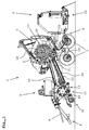
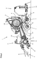
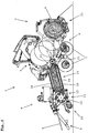
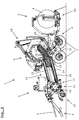
- FIGS. 1 to 5 all show the same embodiment of a continuous round baler 1 in its various phases of operation.
- the illustrated round baler 1 of the example is advantageously combined with a directly mounted bale wrapping device 2 for wrapping the taken over from the baling chamber 3 round bales 4 with foil and then placing the bale 4 on the field.
- Both units rest on a common, via a drawbar 5 with a tractor, especially agricultural tractor, connectable chassis 6, which is supported by wheels 7 to the ground.
- the drive of the entire machine combination via a coupling with the towing vehicle propeller shaft 8, from which the drive energy is branched on the one hand to drive the on-board hydraulics 9 and on the other hand to the mechanically driven components.
- the continuous round baler of the embodiment Since the continuous round baler of the embodiment is designed as a gathering press, it has in the front region a Erntegutier choir 10, a so-called pickup, for receiving lying on the ground mostly in swaths of crop. This is followed in Gut crop direction opposite to the direction of travel F a conveying and cutting device 11, which takes over the crop from the pickup 10 and further promotes by means of a rotor roller 12, where it is optionally cut by switchable cutting blade groups 13 simultaneously. In the further crop flow, a storage space 14 is arranged between the conveying and cutting device 11 and the baling chamber 3, which either temporarily stores the crop further conveyed by the conveying and cutting device 11, or by which the crop is conveyed to the pressing chamber 3.
- the storage space is bounded laterally by side walls and up and down by over its entire length extending conveyors 15, 16.
- the Conveyors 15, 16 are preferably designed as a belt conveyor with drivers, as in the embodiment, or as a bar chain or Stabriemen artister. Designs with conveyor rollers are also conceivable.
- the lower floor conveyor 15 is pivotably mounted at its front end near the conveying and cutting device 11, that the memory space 14 is changed in shape by the vertical displacement of the bottom conveyor 15, at its seen in Gut Wegaid rear end.
- the Fig. 1 and 2 show the bottom conveyor 15 in its upwardly displaced position, whereby a wedge-shaped in the direction of crop flow design of the storage space 14 is effected. In the lower position of the bottom conveyor 15, as in the Fig.
- the bottom conveyor 15 and the top ceiling conveyor 16 of the storage space 14 extend at least parallel or in such a way to each other that the storage space 14 extends slightly to its the pressing chamber 3 facing the end.
- the change of the storage space shape can be done in a further embodiment by an additional adjustment of the upper conveyor 16, but disadvantageously requires additional design effort and costs.
- Subordinate to the storage space in the crop flow follows the baling chamber 3 of the round baler 1.
- the baling chamber 3 is particularly advantageously designed as a semi-variable baling chamber 3. Contrary to a pure variable pressing chamber, this pressing chamber 3 has an initial compression chamber, a starting pressing chamber 17, up to the diameter of which the press operates according to the system of a pure fixed-chamber machine.
- the pressing device 18 Upon further Gutzubow the pressing device 18 deviates outward according to the system of a variable pressing chamber and thus allows the formation of bales of variable sizes, which go beyond the diameter of the starting pressing chamber 17 addition.
- a roller is arranged in the lower region of the pressing chamber 3, which roller is generally known as a starter roller 19. According to the invention, however, it also performs tasks as a conveyor 19 and is therefore sometimes also referred to as such.
- the starter roller 19 is arranged such that it forms the lower boundary of the crop inlet 20 of the pressing chamber 3 from the storage space 14.
- the transfer device 22 is driven in such a way that it immediately assumes its upper starting position after the bale transfer and serves as a collecting trough for eventual debris and already in the press chamber incoming crop, wherein the pressing device 18 of the simultaneously closing pressing chamber 3 strips this good and absorbs lossless in the pressing chamber 3.
- the inventive, controlled by a control and regulating device of the round baler 1 interaction of all modules is characterized by in the FIGS. 1 to 5 illustrated phases of a press cycle illustrates.
- Fig.1 shows a schematic side view of a continuous round baler 1 according to the invention in an operating position, which represents the normal pressing operation.
- Recorded crop is passed directly through the storage space 14 in the pressing chamber 3.
- At least the lower, but advantageous both storage conveyor 15, 16 run while conveying direction pressing chamber 3.
- the lower conveyor 15 and the starter roller 19 are in the upper position.
- a bale 4 is progressively wound to the predetermined size.
- Fig. 2 shows the round baler 1 in the subsequent operating position, which represents the initial phase of the storage operation.
- the pressed bale 4 has reached its predetermined size and strength.
- the net for binding the bale 4 is injected into the bale chamber 3.
- the storage conveyors 15, 16 stop the further supply of crop material into the pressing chamber 3.
- their drive is stopped for a short time and then reversed, or else immediately reversed. Its conveying action against the Erntegut Weg 1 in the direction of the conveying and cutting device 11, causes a merging of the stored material in the storage space 14 with the steadily funded by the conveying and cutting device 11 in the storage space 14 crop, whereby it undergoes a significant pre-pressing.
- the continuously fed into the storage space 14 crop is pressed under pressure in the direction of the pressing chamber 3, wherein it is additionally compressed by the advantageous wedge-shaped configuration of the storage space 14 and holds together.
- the storage conveyors 15, 16 support this process in particular as a function of predetermined and determined crop parameters with regard to their compactability. As a result, they are either stepwise or permanently in the direction of crop flow, or against the direction of crop flow, or not driven.
- the bottom conveyor 15 and the starter roller 19 are still in their upper positions.
- Fig. 3 represents the next phase of the storage process.
- the bottom conveyor 15 is moved to the lower position.
- the storage volume is thereby considerably increased, overloads due to excessive pre-compression are avoided and the further storage operation is ensured.
- the storage conveyors 15, 16 are further controlled as described above.
- Fig. 4 represents the storage process in its final phase.
- the binding process in the pressing chamber 3 is completed.
- the baling chamber 3 is opened automatically and the bale 4 ejected.
- the round bale 4 is gently picked up by the transfer device 22 and passed on in a controlled manner to the bale wrapping device 2 for receiving on the changing table 23.
- this transfer works very reliable only by the gravity of the bale 4.
- the storage space 14 is now completely filled by optimal coordination of the processes to the inlet 20 of the bale chamber 3.
- Fig. 5 represents the round baler 1 in an operating position during the storage emptying phase.
- the starter roller 19 moves with its associated cover 21 in the lower position.
- the inlet opening 20 of the baling chamber 3 expands to at least the full cross-section of the extended storage space 14 at its rear end, which is closest to the baling chamber 3, due to the downwardly displaced bottom conveyor 15.
- the downwardly displaced starter roller 19 forms together with the likewise downwardly displaced bottom conveyor 15 of the storage space 14 and, in the meantime closed pressing chamber 3, directly adjacent to the starter roller 19 pressing device 18 of the pressing chamber 3 an optimal conveyor line for unhindered
- the starter roller 19 is in this phase to the conveyor 19.
- the acting through the cover 21 as a barrier means for the storage space 14 region of the starter roller 19 is due to the lowering of the roller 19th no longer in the crop flow and is therefore ineffective.
- the bottom conveyor 15 and the ceiling conveyor 16 of the storage space 14 are adapted for the fastest possible and continuous transfer of Erntegutwovenes 24 to the conveyor / circulation speeds of the pressing device 18 and the starter roller 19 that they push the cached crop as a package 24 in the pressing chamber 3. There it is taken over by the pressing device 18, immediately set in rotation and used with the subsequent crop as a bale core for further bale formation.
- Fig. 5 clearly shows how advantageous the use of a round baler 1 with semi-variable bale chamber 3 effect.
- the transferred from the storage space 14 Erntegutp 24 has, in the volume exactly matched to the storage volume bale chamber 3, no possibility to expand and dissolve again.
Landscapes
- Life Sciences & Earth Sciences (AREA)
- Environmental Sciences (AREA)
- Storage Of Harvested Produce (AREA)
- Harvesting Machines For Specific Crops (AREA)
- Harvester Elements (AREA)
Claims (7)
- Procédé de commande du flux de produits d'une presse à balles rondes (1), agricole, pour former des balles rondes avec des produits de récolte dans une chambre de presse (3) munie d'installations de presse (18) avec une sortie arrière pour éjecter la balle ronde terminée, un pic-up (10) et en aval, une unité de coupe et/ou de transfert (11), une chambre d'accumulation (14) faisant suite et s'étendant jusqu'à la zone d'entrée (20) de la chambre de presse (3), espace réalisé comme canal de mise en forme et de presse, qui recueille le produit de récolte dans les phases d'accumulation du fonctionnement de la presse et est délimité latéralement par des parois et en bas et en haut par des convoyeurs entraînés (15, 16),- au moins le convoyeur inférieur (15) ayant un côté d'extrémité réglable en hauteur et un dispositif pour le ficelage de la balle ronde terminée avec un matériau de liage dans la chambre de presse (3) et une installation de commande et de régulation,
procédé caractérisé en ce qu'
au moins au début de la phase d'accumulation, l'espace d'accumulation (14) prend une forme de coin allant en diminuant dans la direction de la zone d'entrée (20) de la chambre de presse (3), par le réglage en hauteur d'un côté d'au moins un convoyeur (15, 16), cette forme étant remplie progressivement avec le produit de récolte par l'unité de coupe et/ ou de transfert (11) et pendant le remplissage de l'espace d'accumulation (14) on supprime la forme de coin de cet espace d'accumulation (14) pour que les convoyeurs entraînés (15, 16) de l'espace d'accumulation (14) prennent une position au moins sensiblement parallèle,- la forme de coin se traduisant en plus par la compression du produit de récolte. - Procédé selon la revendication 1,
caractérisé en ce que
la neutralisation de la forme de coin de l'espace d'accumulation (14) est déclenchée de façon commandée pendant la phase d'accumulation, en fonction du temps et/ou de la pression et/ou du degré de remplissage. - Procédé selon au moins l'une des revendications précédentes,
caractérisé en ce qu'
au début de la phase d'accumulation, le convoyeur inférieur (15) délimitant l'espace d'accumulation (14), en inversant le sens du transfert, regroupe les produits de récolte qui se trouvent dans l'espace d'accumulation (14) à contre courant, dans la zone d'entrée de l'espace d'accumulation (14), les produits que l'unité de coupe et/ou de transfert (11) introduit en même temps dans l'espace d'accumulation (14). - Procédé selon l'une des revendications 2 ou 3,
caractérisé en ce qu'
au cours de la poursuite de la phase d'accumulation, avec le remplissage croissant de l'espace d'accumulation (14), l'installation de transfert et de presse (19) de la chambre de presse (3) en combinaison avec un élément de couverture (21), associé comme installation de blocage, bloque le passage des produits de l'espace d'accumulation (14) vers la chambre de presse (3). - Procédé selon la revendication 4,
caractérisé en ce que
dans la suite du processus, l'installation de transfert (19) se déplace, de façon commandée en fonction des événements et/ou du temps, pour supprimer simultanément l'effet de blocage du passage des produits de l'espace d'accumulation (14) vers la chambre de presse (3) et agrandit l'orifice d'entrée (20) de la chambre de presse (3) pour un passage sans obstacle du produit de récolte accumulé provisoirement dans l'espace d'accumulation (14) vers la chambre de presse (3),- l'installation de transfert (19) assistant les convoyeurs entraînés (15, 16) de l'espace d'accumulation (14) pour faire un transfert aussi rapide que possible du produit. - Procédé selon l'une ou plusieurs des revendications précédentes,
caractérisé en ce que
l'installation de commande et de régulation de la presse à balles rondes (1) s'appuyant sur la base d'un temps minimum théorique enregistré pour la compression d'une balle de produit, définit par des paramètres donnés, et en utilisant les paramètres de produit déterminés actuellement, à chaque instant du processus de formation de balles, le flux de produit de façon à obtenir la durée de compression de consigne, déterminée respectivement pour les balles prédéfinies pour un rendement maximum de la machine. - Procédé selon la revendication 6,
caractérisé en ce que
par un asservissement permanent dans le temps entre la consigne et la valeur réelle, en fonction du diamètre actuel de la balle et/ou du poids pendant le développement de la balle, l'installation de commande et de régulation de la presse à balles rondes (1), fournit un signal de consigne de vitesse de fonctionnement à l'unité d'entraînement et/ ou au tracteur, de façon à commander de préférence automatiquement la vitesse de circulation.
Applications Claiming Priority (1)
| Application Number | Priority Date | Filing Date | Title |
|---|---|---|---|
| DE102011111401A DE102011111401B4 (de) | 2011-08-10 | 2011-08-10 | Landwirtschaftliche Rundballenpresse |
Publications (2)
| Publication Number | Publication Date |
|---|---|
| EP2556741A1 EP2556741A1 (fr) | 2013-02-13 |
| EP2556741B1 true EP2556741B1 (fr) | 2017-08-23 |
Family
ID=46880541
Family Applications (1)
| Application Number | Title | Priority Date | Filing Date |
|---|---|---|---|
| EP12005652.8A Not-in-force EP2556741B1 (fr) | 2011-08-10 | 2012-08-03 | Presse à balles rondes agricole |
Country Status (3)
| Country | Link |
|---|---|
| EP (1) | EP2556741B1 (fr) |
| DE (1) | DE102011111401B4 (fr) |
| DK (1) | DK2556741T3 (fr) |
Cited By (1)
| Publication number | Priority date | Publication date | Assignee | Title |
|---|---|---|---|---|
| US11382275B2 (en) | 2016-08-31 | 2022-07-12 | Tube-Line Manufacturing Limited | Continuous round baler accumulation chamber |
Families Citing this family (5)
| Publication number | Priority date | Publication date | Assignee | Title |
|---|---|---|---|---|
| US9949441B2 (en) * | 2011-12-23 | 2018-04-24 | Agco Corporation | Variable speed round bale chamber control with accumulator sensor |
| EP3242545A4 (fr) | 2014-12-02 | 2018-09-26 | McHale Engineering | Presse enrouleuse continue |
| US12029168B2 (en) * | 2014-12-02 | 2024-07-09 | Mchale Engineering | Bale severance mechanism for a continuous round baler |
| CA3156286A1 (fr) | 2019-10-02 | 2021-04-08 | Mchale Engineering | Presse a balles rondes continue a saillie axiale |
| CN112673821A (zh) * | 2020-12-09 | 2021-04-20 | 北京农业智能装备技术研究中心 | 打捆机全自动作业系统 |
Family Cites Families (9)
| Publication number | Priority date | Publication date | Assignee | Title |
|---|---|---|---|---|
| US4011711A (en) | 1976-02-09 | 1977-03-15 | Sperry Rand Corporation | Bale actuated control for the rear roll forming chamber in a crop material roll forming machine |
| DE2634638A1 (de) * | 1976-07-31 | 1978-02-02 | Claas Maschf Gmbh Geb | Rundballenpresse zum bilden von grossballen |
| US4262478A (en) * | 1979-02-07 | 1981-04-21 | Brockadale Developments Limited | Agricultural machine |
| EP0350514A1 (fr) | 1988-07-11 | 1990-01-17 | Maschinenfabrik Bernard Krone GmbH | Presse à balles rondes |
| DE19932336A1 (de) | 1999-07-10 | 2001-01-11 | Lely Welger Maschinenfabrik Gm | Kontinuierlich arbeitende Rundballenpresse |
| DE102004023696B4 (de) | 2004-05-11 | 2007-03-29 | Maschinenfabrik Bernard Krone Gmbh | Maschine zum Aufnehmen und Pressen von landwirtschaftlichem Erntegut |
| DE102005020777A1 (de) | 2005-05-02 | 2006-11-09 | Sacht, Hans Otto, Dr.-Ing. | Kontinuierliche Rundballenpresse für feste Ballen |
| EP2196082B1 (fr) * | 2008-12-10 | 2013-02-27 | Lely Patent N.V. | Presse à ballots ronds fonctionnant en continu |
| NL1037435C2 (en) * | 2009-11-02 | 2011-05-03 | Lely Patent Nv | Baling device to form bales of crop material. |
-
2011
- 2011-08-10 DE DE102011111401A patent/DE102011111401B4/de not_active Expired - Fee Related
-
2012
- 2012-08-03 EP EP12005652.8A patent/EP2556741B1/fr not_active Not-in-force
- 2012-08-03 DK DK12005652.8T patent/DK2556741T3/en active
Non-Patent Citations (1)
| Title |
|---|
| None * |
Cited By (1)
| Publication number | Priority date | Publication date | Assignee | Title |
|---|---|---|---|---|
| US11382275B2 (en) | 2016-08-31 | 2022-07-12 | Tube-Line Manufacturing Limited | Continuous round baler accumulation chamber |
Also Published As
| Publication number | Publication date |
|---|---|
| DE102011111401A1 (de) | 2013-02-14 |
| DE102011111401B4 (de) | 2013-09-26 |
| EP2556741A1 (fr) | 2013-02-13 |
| DK2556741T3 (en) | 2017-12-04 |
Similar Documents
| Publication | Publication Date | Title |
|---|---|---|
| EP2556742B1 (fr) | Presse à balles rondes agricole | |
| EP2556744B1 (fr) | Presse agricole à balles rondes | |
| DE60218400T2 (de) | Rundballenpresse | |
| DE602005006053T2 (de) | Aufsammelgerät für eine landwirtschaftliche Vorrichtung | |
| EP2556741B1 (fr) | Presse à balles rondes agricole | |
| DE4102034A1 (de) | Rundballenpresse | |
| EP1133913A2 (fr) | Presse à balles rondes | |
| EP0324412A1 (fr) | Méthode et appareil pour récolter le fourrage | |
| DE1160229C2 (de) | Verfahren zum aufladen, pressen und horizontalen verteilen von landwirtschaftlichem halm- und blattgut auf einen transportwagen und landwirtschaftliches transportfahrzeug zur durchfuehrung dieses verfahrens | |
| DE102007018329A1 (de) | Kontinuierlich arbeitende Ballenpresse | |
| DE3443719C2 (fr) | ||
| EP1135017B1 (fr) | Presse de mise en bottes sensiblement rectangulaires de produits de recolte | |
| EP0350514A1 (fr) | Presse à balles rondes | |
| DE102011109893A1 (de) | Landwirtschaftliche Rundballenpresse | |
| DE102011109890B4 (de) | Landwirtschaftliche Rundballenpresse | |
| DE4312991A1 (de) | Verfahren und Presse zum Bilden quaderförmiger Preßballen aus landwirtschaftlichem Erntegut | |
| DE102014107178B3 (de) | Ladewagen für aus Halm- oder Blattgut bestehendes Erntegut mit schwenkbarer Stirnwand | |
| EP3981245B1 (fr) | Presse agricole pour fourrage et procédé de dépôt des balles de fourrage comprimé | |
| EP3959961B1 (fr) | Presse pour produits de récolte à tiges pourvu de module de coupe amovible et procédé de manipulation d'un tel module de coupe amovible | |
| EP4282248A1 (fr) | Presse à balles rondes | |
| EP4183244A1 (fr) | Presse à balles rondes | |
| DE3874267T2 (de) | Vereinfachte ballenpresse. | |
| EP4282250B1 (fr) | Presse à balles rondes | |
| DE102004042935B4 (de) | Aufnahme- und Sammelpresse | |
| DE3800479A1 (de) | Verfahren und vorrichtung zum ernten von feldfutter |
Legal Events
| Date | Code | Title | Description |
|---|---|---|---|
| PUAI | Public reference made under article 153(3) epc to a published international application that has entered the european phase |
Free format text: ORIGINAL CODE: 0009012 |
|
| AK | Designated contracting states |
Kind code of ref document: A1 Designated state(s): AL AT BE BG CH CY CZ DE DK EE ES FI FR GB GR HR HU IE IS IT LI LT LU LV MC MK MT NL NO PL PT RO RS SE SI SK SM TR |
|
| AX | Request for extension of the european patent |
Extension state: BA ME |
|
| 17P | Request for examination filed |
Effective date: 20130716 |
|
| RBV | Designated contracting states (corrected) |
Designated state(s): AL AT BE BG CH CY CZ DE DK EE ES FI FR GB GR HR HU IE IS IT LI LT LU LV MC MK MT NL NO PL PT RO RS SE SI SK SM TR |
|
| 17Q | First examination report despatched |
Effective date: 20160407 |
|
| GRAP | Despatch of communication of intention to grant a patent |
Free format text: ORIGINAL CODE: EPIDOSNIGR1 |
|
| INTG | Intention to grant announced |
Effective date: 20170504 |
|
| GRAS | Grant fee paid |
Free format text: ORIGINAL CODE: EPIDOSNIGR3 |
|
| GRAA | (expected) grant |
Free format text: ORIGINAL CODE: 0009210 |
|
| AK | Designated contracting states |
Kind code of ref document: B1 Designated state(s): AL AT BE BG CH CY CZ DE DK EE ES FI FR GB GR HR HU IE IS IT LI LT LU LV MC MK MT NL NO PL PT RO RS SE SI SK SM TR |
|
| REG | Reference to a national code |
Ref country code: GB Ref legal event code: FG4D Free format text: NOT ENGLISH |
|
| REG | Reference to a national code |
Ref country code: CH Ref legal event code: EP |
|
| REG | Reference to a national code |
Ref country code: AT Ref legal event code: REF Ref document number: 920282 Country of ref document: AT Kind code of ref document: T Effective date: 20170915 |
|
| REG | Reference to a national code |
Ref country code: IE Ref legal event code: FG4D Free format text: LANGUAGE OF EP DOCUMENT: GERMAN |
|
| REG | Reference to a national code |
Ref country code: DE Ref legal event code: R096 Ref document number: 502012011068 Country of ref document: DE |
|
| REG | Reference to a national code |
Ref country code: NL Ref legal event code: FP |
|
| REG | Reference to a national code |
Ref country code: DK Ref legal event code: T3 Effective date: 20171127 |
|
| REG | Reference to a national code |
Ref country code: LT Ref legal event code: MG4D |
|
| PG25 | Lapsed in a contracting state [announced via postgrant information from national office to epo] |
Ref country code: NO Free format text: LAPSE BECAUSE OF FAILURE TO SUBMIT A TRANSLATION OF THE DESCRIPTION OR TO PAY THE FEE WITHIN THE PRESCRIBED TIME-LIMIT Effective date: 20171123 Ref country code: FI Free format text: LAPSE BECAUSE OF FAILURE TO SUBMIT A TRANSLATION OF THE DESCRIPTION OR TO PAY THE FEE WITHIN THE PRESCRIBED TIME-LIMIT Effective date: 20170823 Ref country code: SE Free format text: LAPSE BECAUSE OF FAILURE TO SUBMIT A TRANSLATION OF THE DESCRIPTION OR TO PAY THE FEE WITHIN THE PRESCRIBED TIME-LIMIT Effective date: 20170823 Ref country code: HR Free format text: LAPSE BECAUSE OF FAILURE TO SUBMIT A TRANSLATION OF THE DESCRIPTION OR TO PAY THE FEE WITHIN THE PRESCRIBED TIME-LIMIT Effective date: 20170823 Ref country code: LT Free format text: LAPSE BECAUSE OF FAILURE TO SUBMIT A TRANSLATION OF THE DESCRIPTION OR TO PAY THE FEE WITHIN THE PRESCRIBED TIME-LIMIT Effective date: 20170823 |
|
| PG25 | Lapsed in a contracting state [announced via postgrant information from national office to epo] |
Ref country code: LV Free format text: LAPSE BECAUSE OF FAILURE TO SUBMIT A TRANSLATION OF THE DESCRIPTION OR TO PAY THE FEE WITHIN THE PRESCRIBED TIME-LIMIT Effective date: 20170823 Ref country code: IS Free format text: LAPSE BECAUSE OF FAILURE TO SUBMIT A TRANSLATION OF THE DESCRIPTION OR TO PAY THE FEE WITHIN THE PRESCRIBED TIME-LIMIT Effective date: 20171223 Ref country code: PL Free format text: LAPSE BECAUSE OF FAILURE TO SUBMIT A TRANSLATION OF THE DESCRIPTION OR TO PAY THE FEE WITHIN THE PRESCRIBED TIME-LIMIT Effective date: 20170823 Ref country code: RS Free format text: LAPSE BECAUSE OF FAILURE TO SUBMIT A TRANSLATION OF THE DESCRIPTION OR TO PAY THE FEE WITHIN THE PRESCRIBED TIME-LIMIT Effective date: 20170823 Ref country code: GR Free format text: LAPSE BECAUSE OF FAILURE TO SUBMIT A TRANSLATION OF THE DESCRIPTION OR TO PAY THE FEE WITHIN THE PRESCRIBED TIME-LIMIT Effective date: 20171124 Ref country code: ES Free format text: LAPSE BECAUSE OF FAILURE TO SUBMIT A TRANSLATION OF THE DESCRIPTION OR TO PAY THE FEE WITHIN THE PRESCRIBED TIME-LIMIT Effective date: 20170823 Ref country code: BG Free format text: LAPSE BECAUSE OF FAILURE TO SUBMIT A TRANSLATION OF THE DESCRIPTION OR TO PAY THE FEE WITHIN THE PRESCRIBED TIME-LIMIT Effective date: 20171123 |
|
| PG25 | Lapsed in a contracting state [announced via postgrant information from national office to epo] |
Ref country code: RO Free format text: LAPSE BECAUSE OF FAILURE TO SUBMIT A TRANSLATION OF THE DESCRIPTION OR TO PAY THE FEE WITHIN THE PRESCRIBED TIME-LIMIT Effective date: 20170823 Ref country code: CZ Free format text: LAPSE BECAUSE OF FAILURE TO SUBMIT A TRANSLATION OF THE DESCRIPTION OR TO PAY THE FEE WITHIN THE PRESCRIBED TIME-LIMIT Effective date: 20170823 |
|
| REG | Reference to a national code |
Ref country code: DE Ref legal event code: R097 Ref document number: 502012011068 Country of ref document: DE |
|
| PG25 | Lapsed in a contracting state [announced via postgrant information from national office to epo] |
Ref country code: SM Free format text: LAPSE BECAUSE OF FAILURE TO SUBMIT A TRANSLATION OF THE DESCRIPTION OR TO PAY THE FEE WITHIN THE PRESCRIBED TIME-LIMIT Effective date: 20170823 Ref country code: EE Free format text: LAPSE BECAUSE OF FAILURE TO SUBMIT A TRANSLATION OF THE DESCRIPTION OR TO PAY THE FEE WITHIN THE PRESCRIBED TIME-LIMIT Effective date: 20170823 Ref country code: SK Free format text: LAPSE BECAUSE OF FAILURE TO SUBMIT A TRANSLATION OF THE DESCRIPTION OR TO PAY THE FEE WITHIN THE PRESCRIBED TIME-LIMIT Effective date: 20170823 Ref country code: IT Free format text: LAPSE BECAUSE OF FAILURE TO SUBMIT A TRANSLATION OF THE DESCRIPTION OR TO PAY THE FEE WITHIN THE PRESCRIBED TIME-LIMIT Effective date: 20170823 |
|
| PLBE | No opposition filed within time limit |
Free format text: ORIGINAL CODE: 0009261 |
|
| STAA | Information on the status of an ep patent application or granted ep patent |
Free format text: STATUS: NO OPPOSITION FILED WITHIN TIME LIMIT |
|
| 26N | No opposition filed |
Effective date: 20180524 |
|
| PG25 | Lapsed in a contracting state [announced via postgrant information from national office to epo] |
Ref country code: SI Free format text: LAPSE BECAUSE OF FAILURE TO SUBMIT A TRANSLATION OF THE DESCRIPTION OR TO PAY THE FEE WITHIN THE PRESCRIBED TIME-LIMIT Effective date: 20170823 |
|
| PG25 | Lapsed in a contracting state [announced via postgrant information from national office to epo] |
Ref country code: MT Free format text: LAPSE BECAUSE OF FAILURE TO SUBMIT A TRANSLATION OF THE DESCRIPTION OR TO PAY THE FEE WITHIN THE PRESCRIBED TIME-LIMIT Effective date: 20170823 |
|
| PG25 | Lapsed in a contracting state [announced via postgrant information from national office to epo] |
Ref country code: MC Free format text: LAPSE BECAUSE OF FAILURE TO SUBMIT A TRANSLATION OF THE DESCRIPTION OR TO PAY THE FEE WITHIN THE PRESCRIBED TIME-LIMIT Effective date: 20170823 |
|
| REG | Reference to a national code |
Ref country code: CH Ref legal event code: PL |
|
| GBPC | Gb: european patent ceased through non-payment of renewal fee |
Effective date: 20180803 |
|
| PG25 | Lapsed in a contracting state [announced via postgrant information from national office to epo] |
Ref country code: CH Free format text: LAPSE BECAUSE OF NON-PAYMENT OF DUE FEES Effective date: 20180831 Ref country code: LI Free format text: LAPSE BECAUSE OF NON-PAYMENT OF DUE FEES Effective date: 20180831 Ref country code: LU Free format text: LAPSE BECAUSE OF NON-PAYMENT OF DUE FEES Effective date: 20180803 |
|
| REG | Reference to a national code |
Ref country code: BE Ref legal event code: MM Effective date: 20180831 |
|
| PG25 | Lapsed in a contracting state [announced via postgrant information from national office to epo] |
Ref country code: BE Free format text: LAPSE BECAUSE OF NON-PAYMENT OF DUE FEES Effective date: 20180831 Ref country code: FR Free format text: LAPSE BECAUSE OF NON-PAYMENT OF DUE FEES Effective date: 20180831 |
|
| REG | Reference to a national code |
Ref country code: AT Ref legal event code: MM01 Ref document number: 920282 Country of ref document: AT Kind code of ref document: T Effective date: 20180803 |
|
| PG25 | Lapsed in a contracting state [announced via postgrant information from national office to epo] |
Ref country code: GB Free format text: LAPSE BECAUSE OF NON-PAYMENT OF DUE FEES Effective date: 20180803 |
|
| PG25 | Lapsed in a contracting state [announced via postgrant information from national office to epo] |
Ref country code: AT Free format text: LAPSE BECAUSE OF NON-PAYMENT OF DUE FEES Effective date: 20180803 |
|
| PG25 | Lapsed in a contracting state [announced via postgrant information from national office to epo] |
Ref country code: TR Free format text: LAPSE BECAUSE OF FAILURE TO SUBMIT A TRANSLATION OF THE DESCRIPTION OR TO PAY THE FEE WITHIN THE PRESCRIBED TIME-LIMIT Effective date: 20170823 |
|
| PG25 | Lapsed in a contracting state [announced via postgrant information from national office to epo] |
Ref country code: PT Free format text: LAPSE BECAUSE OF FAILURE TO SUBMIT A TRANSLATION OF THE DESCRIPTION OR TO PAY THE FEE WITHIN THE PRESCRIBED TIME-LIMIT Effective date: 20170823 Ref country code: HU Free format text: LAPSE BECAUSE OF FAILURE TO SUBMIT A TRANSLATION OF THE DESCRIPTION OR TO PAY THE FEE WITHIN THE PRESCRIBED TIME-LIMIT; INVALID AB INITIO Effective date: 20120803 |
|
| PG25 | Lapsed in a contracting state [announced via postgrant information from national office to epo] |
Ref country code: MK Free format text: LAPSE BECAUSE OF NON-PAYMENT OF DUE FEES Effective date: 20170823 Ref country code: CY Free format text: LAPSE BECAUSE OF FAILURE TO SUBMIT A TRANSLATION OF THE DESCRIPTION OR TO PAY THE FEE WITHIN THE PRESCRIBED TIME-LIMIT Effective date: 20170823 |
|
| PG25 | Lapsed in a contracting state [announced via postgrant information from national office to epo] |
Ref country code: AL Free format text: LAPSE BECAUSE OF FAILURE TO SUBMIT A TRANSLATION OF THE DESCRIPTION OR TO PAY THE FEE WITHIN THE PRESCRIBED TIME-LIMIT Effective date: 20170823 |
|
| REG | Reference to a national code |
Ref country code: DE Ref legal event code: R081 Ref document number: 502012011068 Country of ref document: DE Owner name: KRONE AGRICULTURE SE, DE Free format text: FORMER OWNER: MASCHINENFABRIK BERNARD KRONE GMBH, 48480 SPELLE, DE |
|
| REG | Reference to a national code |
Ref country code: NL Ref legal event code: PD Owner name: KRONE AGRICULTURE SE; DE Free format text: DETAILS ASSIGNMENT: CHANGE OF OWNER(S), MERGE; FORMER OWNER NAME: MASCHINENFABRIK KRONE BETEILIGUNGS- GMBH Effective date: 20210909 Ref country code: NL Ref legal event code: HC Owner name: MASCHINENFABRIK KRONE BETEILIGUNGS- GMBH; DE Free format text: DETAILS ASSIGNMENT: CHANGE OF OWNER(S), CHANGE OF OWNER(S) NAME; FORMER OWNER NAME: MASCHINENFABRIK BERNARD KRONE GMBH Effective date: 20210909 |
|
| PGFP | Annual fee paid to national office [announced via postgrant information from national office to epo] |
Ref country code: NL Payment date: 20220822 Year of fee payment: 11 |
|
| PGFP | Annual fee paid to national office [announced via postgrant information from national office to epo] |
Ref country code: IE Payment date: 20220819 Year of fee payment: 11 Ref country code: DK Payment date: 20220824 Year of fee payment: 11 Ref country code: DE Payment date: 20220822 Year of fee payment: 11 |
|
| P01 | Opt-out of the competence of the unified patent court (upc) registered |
Effective date: 20230517 |
|
| REG | Reference to a national code |
Ref country code: DE Ref legal event code: R119 Ref document number: 502012011068 Country of ref document: DE |
|
| REG | Reference to a national code |
Ref country code: DK Ref legal event code: EBP Effective date: 20230831 |
|
| REG | Reference to a national code |
Ref country code: NL Ref legal event code: MM Effective date: 20230901 |
|
| PG25 | Lapsed in a contracting state [announced via postgrant information from national office to epo] |
Ref country code: NL Free format text: LAPSE BECAUSE OF NON-PAYMENT OF DUE FEES Effective date: 20230901 |
|
| REG | Reference to a national code |
Ref country code: IE Ref legal event code: MM4A |
|
| PG25 | Lapsed in a contracting state [announced via postgrant information from national office to epo] |
Ref country code: NL Free format text: LAPSE BECAUSE OF NON-PAYMENT OF DUE FEES Effective date: 20230901 |
|
| PG25 | Lapsed in a contracting state [announced via postgrant information from national office to epo] |
Ref country code: IE Free format text: LAPSE BECAUSE OF NON-PAYMENT OF DUE FEES Effective date: 20230803 |
|
| PG25 | Lapsed in a contracting state [announced via postgrant information from national office to epo] |
Ref country code: DK Free format text: LAPSE BECAUSE OF NON-PAYMENT OF DUE FEES Effective date: 20230831 |
|
| PG25 | Lapsed in a contracting state [announced via postgrant information from national office to epo] |
Ref country code: IE Free format text: LAPSE BECAUSE OF NON-PAYMENT OF DUE FEES Effective date: 20230803 Ref country code: DK Free format text: LAPSE BECAUSE OF NON-PAYMENT OF DUE FEES Effective date: 20230831 Ref country code: DE Free format text: LAPSE BECAUSE OF NON-PAYMENT OF DUE FEES Effective date: 20240301 |