EP3981245B1 - Presse agricole pour fourrage et procédé de dépôt des balles de fourrage comprimé - Google Patents
Presse agricole pour fourrage et procédé de dépôt des balles de fourrage comprimé Download PDFInfo
- Publication number
- EP3981245B1 EP3981245B1 EP21198191.5A EP21198191A EP3981245B1 EP 3981245 B1 EP3981245 B1 EP 3981245B1 EP 21198191 A EP21198191 A EP 21198191A EP 3981245 B1 EP3981245 B1 EP 3981245B1
- Authority
- EP
- European Patent Office
- Prior art keywords
- bales
- support table
- press
- stalk press
- ground
- Prior art date
- Legal status (The legal status is an assumption and is not a legal conclusion. Google has not performed a legal analysis and makes no representation as to the accuracy of the status listed.)
- Active
Links
Images




Classifications
-
- A—HUMAN NECESSITIES
- A01—AGRICULTURE; FORESTRY; ANIMAL HUSBANDRY; HUNTING; TRAPPING; FISHING
- A01F—PROCESSING OF HARVESTED PRODUCE; HAY OR STRAW PRESSES; DEVICES FOR STORING AGRICULTURAL OR HORTICULTURAL PRODUCE
- A01F15/00—Baling presses for straw, hay or the like
- A01F15/08—Details
- A01F15/0875—Discharge devices
- A01F15/0883—Discharge devices for round balers
-
- A—HUMAN NECESSITIES
- A01—AGRICULTURE; FORESTRY; ANIMAL HUSBANDRY; HUNTING; TRAPPING; FISHING
- A01F—PROCESSING OF HARVESTED PRODUCE; HAY OR STRAW PRESSES; DEVICES FOR STORING AGRICULTURAL OR HORTICULTURAL PRODUCE
- A01F15/00—Baling presses for straw, hay or the like
- A01F15/08—Details
- A01F15/0875—Discharge devices
Definitions
- the present invention relates to an agricultural crop press with the features of independent claim 1 for pressing cuboid bales or large bales in particular.
- the invention also relates to a method for depositing cuboid bales or large bales, in particular, with the features of independent method claim 10.
- the harvested stalks represent an important raw material that is required in many agricultural process chains.
- grain straw which is produced in comparatively large quantities in connection with combine harvesting, can be required as bedding for stable animals, while hay can form valuable animal feed for grazing animals, which, as large agricultural livestock, often do not go to the pasture but are fed in the stable.
- agricultural tractors with hydraulic lifting devices mounted on the front are used for handling the pressed portions or piece goods formed from harvested stalks.
- so-called yard loaders have proven themselves and have become established in many places. or straw bales are available.
- a first common variant for forming cylindrical bales takes up the stalks lying in windrows on the field and ensures that it is in the machine wrapped around a central longitudinal axis and tied together with sisal twine or other suitable twine prior to being ejected from the rear of the machine.
- the round bales formed and pressed in this way are finally deposited on the field by each pressed bale being ejected or rolled out through an opening at the rear of the round baler in order to lie on its cylindrical surface without further treatment or processing.
- bales deposited in the field in this way can then be picked up in a subsequent operation by means of mobile forks arranged on a hydraulic lifting device of an agricultural tractor or a farm loader and taken directly to the nearby farm or, for a longer transport route, to a groupage vehicle such as an open trailer and be charged there.
- a second variant which is also very common and is referred to as a bale press or large bale press, forms cuboid bales that are formed from the hay or straw that has been picked up in a continuous manufacturing, forming and conveying process and, after binding, via a rear attachment to the attached and by means of the so-called chute that is pulled by an agricultural tractor and attached by means of its PTO shaft-driven pack press and placed on the field.
- Further handling i.e. picking up, loading, stacking, etc. e.g. on a trailer, can essentially be the same as with round bales, although it should be noted that cuboid bales can be stacked more easily and space-savingly and in larger quantities than the round bales that require more space when stacking.
- Such pack or bale presses have a rotating pick-up unit, a so-called pick-up, with which the crop lying on the field is picked up and transferred to the machine.
- the harvested crop can then be brought together from the sides in the direction of the center with the help of screw conveyors, since the downstream cutterbars and baling channels are generally designed to be significantly narrower than the pickup pick-up and the overall width of the baler. While the overall width of such a towed press can be a little more than two meters, the width of the packs or bales formed with it is usually only a little more than one meter.
- Big balers do not necessarily have a cutter, while the pack press or big pack press defined here and described in more detail below on the basis of their essential features has a cutter with a large number of parallel cutting knives, with which the picked crop can be cut into smaller sections, provided that this is Connection with the pressing process and the process of pack formation is desired. If such a cutting mechanism is present, it is typically located directly behind the auger junction in the conveying direction. Most big bale or big pack presses have a pre-pressing device that is able to pre-compact the mass of the harvested crop in smaller partial packages and then to transfer the partial packages into the main baling chamber. In this way it can be ensured that the main baling chamber does not have to process and press an uncompacted crop flow immediately, which would not make sense with the usual performance ranges of large baling presses or large pack presses.
- bale or pack is wrapped with twine and the twine is knotted.
- the harvested crop is compressed in the bale chamber by the piston until a corresponding bale or pack counter-pressure is built up in the bale channel by the ejection device.
- twine feed and the binding device with the knotter are triggered and the bale or pack is bound.
- the tied bale or pack is then carried on to the ejection device, the so-called chute, and finally ejected from the rear by the dynamic pressure and the uninterrupted supply of further bales or packs.
- the supply of the pre-compacted partial packets of stalks is discontinuous and inevitably depends on the respective position of the plunger.
- the bale chamber can be filled, as the feed opening is accessible.
- the piston of the main baling chamber is advanced, whereby the cuboid big pack is formed, in order to then be wrapped with twine, after which the twine is knotted.
- the DE 1 215 998 B discloses a bale guide at the exit of the press channel of a baling press, which is intended to prevent irregular and indiscriminate depositing of cuboid bales, which is recognized as disadvantageous.
- a combined device for turning and correcting the position of the bales is therefore proposed, a bottom plate of a press channel outlet together with an adjustable guide device can tilt the ejected bales by about 90° around their horizontal longitudinal axis.
- a bale leaving the baling channel passes through a chute and, as a result of a partially recessed floor panel, tips over in a defined lateral direction, whereby this rotary movement is limited to a rotary angle of 90°, as a result of which all ejected bales inevitably remain on a narrow longitudinal edge.
- Tilting devices similar to this known system which are each mounted at the rear on the ejection sides of balers, can also be found in U.S. 2,853,171 , in the U.S. 3,161,008 A as well as in the U.S. 5,024,152 A disclosed.
- an agricultural crop press for pressing cuboid bales in which the bales are pushed out at the rear from a pressing area onto a depositing table, which has a rotatable platform that can be lowered at an angle in the rear direction, so that the bale to be placed in each case can be rotated 90° around a vertical axis can be rotated. Since there are no other guide devices apart from this support platform, the bales are placed on the ground comparatively imprecisely.
- U.S. 6,033,172 A A mechanical device similar in some respects is found in U.S. 6,033,172 A disclosed.
- a turning and depositing device that can be coupled to the rear of a baling press is described, which has a support table that can be rotated about a vertical axis and at the same time tilted backwards at an angle for depositing individual bales on the ground, with the bales being able to be rotated before they are placed on the ground. Since the bales slide off the sloping support table solely under their own weight and are placed on the ground, the placement precision is also lacking here.
- the primary aim of the present invention is to equip a conventional stalk baler, in particular in the form of a bale press or large bale press, with as little structural effort as possible in such a way that the pressed bales, which are conveyed out of the press in the direction of deposit, are rotated by one before they are deposited on the ground defined angle of rotation can be rotated about a particular vertical axis of rotation.
- the invention proposes an agricultural crop press for pressing cuboid bales or large bales, in particular, which is equipped with a receiving device for receiving harvested crops, with an optional cutting module downstream of the receiving device in the conveying direction of the harvested crops for chopping up the harvested crops, and with a dem optionally available cutting module downstream pressing device for pressing the harvested crop into bales of a defined size is equipped.
- the pressing device is preferably assigned a binding device that can wrap and knot twine around a finished bale or big bale, since it is normally necessary to fix bales or big bales that have been compacted by pressing in their shape, which in practice makes sense by means of tying and subsequent knotting the tying can be done.
- the crop press comprises a conveying and/or depositing device downstream of the pressing device for ejecting finished bales or large bales wrapped with twine.
- the agricultural crop baler according to the invention is also equipped with a conveying and/or depositing device arranged downstream of the pressing device for ejecting finished bales that have been pressed and wrapped with twine.
- This conveying and/or depositing device has a support table, which can be rotated about an approximately vertical axis, with a laterally adjoining inclined ramp for the controlled depositing of bales on the ground.
- the rotatable support table is also assigned a sliding device for pushing bales or large bales on the support table to the inclined ramp.
- This configuration allows the square bales or big bales that have been pressed, tied and placed on the ground to be arranged on the ground in such a way that they can be picked up more easily and quickly than before using handling devices prepared for this purpose and stacked to save space. Since in this way the pressed bales and conveyed out of the press in the direction of deposit were rotated by a defined angle of rotation around a vertical axis of rotation in particular before being deposited on the ground, their narrow sides, which are normally not easily accessible with conventional depositing, are now laterally accessible for a piercing process using fork tines, so that they can consequently also be picked up with an approach from one side of the storage row and placed on a trailer and stacked without further turning or setting down.
- the cuboid bales or big bales can lie against each other with their long sides, which is particularly advantageous in multi-row storage and allows faster stacking and storage processes, and this in denser packing of the bales or big bales than in a conventional storage.
- the support table can be equipped in particular with rollers arranged parallel to one another, which form a support surface for horizontal transport of bales, and on which the bales can roll or roll with little resistance while they are pushed off the inclined ramp and onto the floor can be stored.
- the rollers of the support table can be passively mounted so that they can each rotate freely about their horizontal axes of rotation when a bale is on the rollers is moved.
- the tops of several rollers arranged in parallel thus form the support surface of the support table.
- the rollers of the support table are each provided with drives in order to be able to push off bales and place them on the floor.
- the pushing device can comprise at least one push bar which can be moved horizontally and/or parallel to the support surface of the support table.
- the bales can be transported in the direction of the sloping ramp with this pushing bar of the pushing device and placed on the ground in front of them.
- a further embodiment of the agricultural crop press according to the invention can also be provided that the movable support table is rotatably mounted on a frame section which is coupled to the rear of the crop press and/or attached to the rear of the crop press.
- At least one support wheel rolling on the ground is located below the support table, which wheel can optionally also be designed as a twin support wheel.
- a support wheel or twin support wheel can prevent an excessive weight from the support table hinged at the rear, together with the inclined ramp attached to it and the bale carried by it, having to be suspended in a self-supporting manner at the rear of the crop baler without additional support.
- a support wheel rolling on the ground or a suitable support wheel construction can easily support these not inconsiderable weights and mechanically relieve the articulated connection to the crop press.
- the frame section can be designed, for example, as a trailer that is attached to the rear of the crop press and detachably coupled to it.
- a trailer expediently comprises the already mentioned support wheel or the mentioned support wheel construction.
- the frame section can also be hinged at the rear of the straw press and form a movable part of this straw press, which remains firmly connected to the straw press, the frame section in the Use case can also be designed as a trailer or a trailer-like element.
- the inclined ramp located on a long or narrow side of the rotatable support table can be variably adjusted in its angle to the support surface of the support table in order to compensate for different ground conditions or to be able to set different distances between a lower edge of the inclined ramp and the ground .
- the inclined ramp comprises a number of rollers which together form a conveying plane for the bales, which can roll off on this inclined conveying plane.
- the rollers of the inclined ramp can each be passively mounted, whereby they each rotate about horizontal axes of rotation, these axes of rotation lying approximately transversely to the conveying and pushing-off direction of the bales rolling on them, so that they can optimally support the conveying or rolling movement.
- rollers of the inclined ramp can each be optionally provided with drives in order to be able to push off bales and deposit them on the ground.
- a first end position can be formed in that the narrow sides of the support table are aligned transversely to a direction of travel or longitudinal direction of the crop press, and that the long sides of the support table are aligned parallel to the direction of travel and at the same time are aligned with the long sides of the crop press.
- This first end position forms the standard case in which the bales are discharged from the crop press in the usual way with their narrow sides pointing backwards, so that their longer sides are aligned parallel to the direction of travel of the crop press.
- the inclined ramp is also aligned parallel to the direction of travel or longitudinal direction of the crop press and is located on a longitudinal side of the conveying and/or depositing device of the crop press.
- a second end position is formed in that the long sides of the support table are aligned transversely to a direction of travel or longitudinal direction of the crop press, and that the narrow sides of the support table are aligned parallel to the direction of travel and are aligned with the long sides of the crop press.
- the inclined ramp is aligned transversely to the direction of travel or longitudinal direction of the straw baler and is located at the rear of the conveying and/or depositing device or points in a direction opposite to the direction of travel of the straw baler, so that the rotated bales can be deposited on the rear .
- the support table can be coupled to a motor-driven actuator, which can ensure controlled rotation and reverse rotation and/or a rotary movement between the two end positions.
- a motor-driven actuator can, for example, be a motorized direct drive that can rotate the supporting table in the desired manner.
- Other actuators are also conceivable, for example hydraulically or pneumatically actuated adjusting cylinders, which are preferably arranged below the support table and can rotate or pivot it in the desired manner.
- the sliding device can also be coupled to a motor-driven actuator which can ensure a controlled movement and return movement of the push beam in the linear direction.
- Hydraulically or pneumatically actuated positioning cylinders for example, which can provide the required linear movement, are also suitable for this.
- the present invention proposes, in addition to the agricultural crop press explained in various design variants, a method for depositing cuboid bales or large bales in particular, which were pressed from crops picked up from the ground by means of an agricultural crop press, in particular by means of an agricultural crop press according to one of the previously explained variants.
- the bales are discharged via a conveying and/or depositing device arranged at the rear of the straw press, where they are rotated about an approximately vertical axis and by means of pushed over to a sloping ramp by a sliding device and placed on the ground in a controlled manner.
- the bales are preferably rotated by about 90° about an approximately vertical axis and placed on the ground with their long sides transverse to the direction of travel. This means that by turning the bales by around 90° around an approximately vertical axis, they are placed on the ground with their narrow sides parallel to the direction of travel.
- the bales are deposited in a lane of the straw baler via the inclined ramp arranged at the rear of the straw baler.
- the support table of the straw baler is rotated by about 90° each time a bale is on it.
- the push bar can be activated and the bale pushed backwards over the inclined ramp and deposited on the ground.
- the support table can be turned back again in order to be able to pick up another bale, which is conveyed out of the crop press.
- the agricultural crop press according to the invention can be used in a known manner for pressing cuboid bales or large bales. Since such a crop press, in contrast to a so-called bale press, does not form cylindrical crop bales, but cuboid bales, it is usually also referred to as a pack press or large pack press.
- Such an agricultural crop press normally has a drawbar on the front, so that the crop press is a towed vehicle without its own drive, which can be attached to a suitable hitch on a rear area of an agricultural tractor such as a tractor.
- the chassis of the straw baler can, for example, have a twin axle with a total of four relatively wide support wheels, so that even heavier loads can be supported on the field without excessive ground pressure.
- a housing can be located on top of the chassis, in which the components of the agricultural crop press explained below are accommodated.
- ground-reaching pick-up device Immediately behind and below the drawbar and clearly in front of the twin axle with the four support wheels is a ground-reaching pick-up device, which can also be referred to as a pick-up, and which is used to pick up crops or stalks.
- harvested crop or stalk crop used here in general refers here in particular to harvest residues from a combine harvesting process or else dried hay after a meadow or similar mowing process.
- Lateral support wheels or support rollers can optionally be provided on the receiving device so that the receiving device with a normally driven tine roller or feed roller rotating about a horizontal axis transverse to a longitudinal center axis of the straw baler can maintain a constant distance from the ground.
- the material flow through the straw baler runs from front to back through the entire machine. Accordingly, between the housing and the receiving device in the conveying direction of the harvested crop there is a cutting module which is arranged downstream of the receiving device and is used to chop up the harvested crop.
- the cutting module for example.
- the cutting blades of the blade cassette can be adjusted in particular by a motor in order to be able to vary the stalk length of the stalks or crops to be pressed, so that depending on the setting of the cutting blades, different stalk lengths can be set and the recorded stalks can be cut accordingly.
- the straw press includes a pressing device which is arranged downstream of the cutting module and is located within the housing.
- the pressing device serves to press the harvested crop that has been picked up and conveyed through the machine in the material flow direction into bales of a defined size, with the pressing device also being assigned a binding device that wraps and knots twine around a finished bale or large bale.
- a conveying and/or depositing device downstream of the pressing device, through which the finished bales or big bales wrapped with twine are pushed out or ejected in a longitudinal direction, i.e. approximately parallel to the longitudinal center axis of the straw baler.
- This conveying and/or depositing device is often also referred to as a chute.
- the material flow extends from the ground in front of the pick-up device through the pick-up device to the cutting module and from there into the housing with the pressing device located therein, before it leads through the chute or the conveying and/or storage device to the rear and out the rear of the crop press.
- the flow of material is thus essentially oriented in the opposite direction to the normal direction of travel of the crop baler.
- the ejected cuboid bales or large bales can also be rotated around a vertical axis.
- the bales on a downstream conveying and/or depositing device are first rotated by 90° around the vertical axis and then rotated in this by means of a support table that can be rotated about an approximately vertical axis with an inclined ramp adjoining it on the edge Position shifted backwards.
- the rotatable support table is assigned a sliding device for pushing bales or large bales on the support table to the inclined ramp.
- the support table can be formed, for example, by a plurality of square tubes connected to one another, on the flat tops of which bales moved by means of the sliding device can slide.
- the flat tops of the square tubes form a support surface for the support table.
- the sliding device can in particular comprise a push bar which can be moved in the horizontal direction and thus also parallel to the support surface of the support table at a small distance from it.
- the bales can be transported in the direction of the sloping ramp with this pushing bar of the pushing device and placed on the ground in front of them.
- the support table can be moved about the vertical axis of rotation, it is rotatably mounted on a frame section or chassis which is coupled to the crop press and attached to the rear thereof.
- a twin support wheel rolling on the floor can be located approximately in the middle below the support table, whereby all the weight forces that arise can be supported on the floor without any problems and the articulated connection to the crop press can be mechanically relieved.
- the frame section with the support table rotatably mounted thereon is in particular foldably suspended at the rear of the crop press and in this way forms a movable part of the crop press.
- the frame section remains firmly connected to the straw baler, and when in use it can be designed as a trailer or as a trailer-like element that is supported on the ground while rolling on the support wheel.
- the inclined ramp located on one long side of the rotatable support table can be variably adjustable in its angle to the support surface of the support table in order to compensate for different ground conditions or to be able to set different distances between a lower edge of the inclined ramp and the ground.
- the inclined ramp can comprise a plurality of rotatable rollers which together form a conveying plane for the bales which can roll off on this inclined conveying plane.
- the rollers of the inclined ramp can each be mounted passively, each rotating about horizontal axes of rotation, with these The axes of rotation are approximately transverse to the conveying and pushing-off direction of the bales rolling on it, so that they can optimally support the conveying or rolling movement.
- the narrow sides of the support table are aligned transversely to the direction of travel or longitudinal direction of the crop press, while the long sides of the support table are aligned parallel to the direction of travel and at the same time are aligned with the long sides of the crop press.
- This first end position forms the standard case in which the bales are discharged from the crop press in the usual way with their narrow sides pointing backwards, so that their longer sides are aligned parallel to the direction of travel of the crop press.
- the inclined ramp is also aligned parallel to the direction of travel or longitudinal direction of the crop press and is located on a longitudinal side of the support table of the conveying and/or depositing device.
- the bales are pushed onto the support surface of the support table.
- a second end position of the support table is formed in that the long sides of the support table are aligned transversely to the direction of travel or longitudinal direction of the straw press, and that the narrow sides of the support table are aligned parallel to the direction of travel and are aligned with the long sides of the straw press.
- the inclined ramp is aligned transversely to the direction of travel or longitudinal direction of the straw baler and is located at the rear of the conveying and/or depositing device or points in a direction opposite to the direction of travel of the straw baler, so that the rotated bales can be deposited on the rear .
- the bales rotated in this way are placed with their long sides transverse to the direction of travel and opposite to this to the rear over the inclined ramp.
- the support table can be turned back through 90° to the starting position shown above, i.e. to the first end position.
- the support table can be coupled to a motor-driven actuator or drive motor, which can ensure controlled rotation and reverse rotation and/or rotary movement between the two end positions.
- a motor-driven actuator or drive motor can, for example.
- Other actuators are also conceivable, for example hydraulically or pneumatically actuated adjusting cylinders, which are preferably arranged below the support table and can rotate or pivot it in the desired manner.
- the sliding device can preferably also be coupled to a motor-driven actuator which can ensure a controlled movement and return movement of the push bar in the linear direction.
- Hydraulically or pneumatically actuated positioning cylinders for example, which can provide the required linear movement, are also suitable for this.
- the schematic perspective view of the Figure 1A shows a variant of an agricultural straw baler 10, which is used for pressing cuboid bales or large bales. Since such a crop press 10, in contrast to a so-called bale press, does not form cylindrical crop bales, but cuboid bales, it is usually also referred to as a pack press or large pack press. Since these designations are not always uniform in practice and can be used optionally, in the present context all these mentioned designations of the agricultural machine - be it the crop press, the baler or the big baler - are each assigned the reference number 10.
- FIG. 1A Like this the perspective view of Figure 1A obliquely from behind on the left longitudinal side of the agricultural crop press 10, this has a front drawbar 12, so that the crop press 10 can form a towed vehicle without its own drive, which can be attached to a suitable trailer device on a rear area of an agricultural tractor (not shown here). shown) can be attached.
- the chassis of the crop press 10 has a twin axle 14 with a total of four relatively wide support wheels 16, so that even heavier loads can be supported on the field without excessive ground pressure.
- a housing 18 can be seen on the upper side of the chassis, in which further components of the agricultural crop press 10 explained below are accommodated.
- ground-reaching pick-up device 20 which is often also referred to as a pick-up, and which is used to pick up crops or stalks.
- harvested crops or straw crops which is generally used here, refers in particular to crop residues a combine threshing process or also dried hay after mowing a meadow or the like.
- Lateral support wheels 26 are provided so that the pick-up device 20 with a normally driven tine roller or feed roller 24 rotating about a horizontal axis 22 of the crop baler 10 can maintain a constant distance from the ground Figure 1A only the left of these two support wheels 26 can be seen.
- the cutting module 30 which is arranged downstream of the receiving device 20 and serves to chop up the harvested crop.
- the cutting module 30 can comprise, for example, a blade cartridge (not shown here in detail) with a multiplicity of cutting blades fastened or stored there, and a rotating blade roller (also not shown here) in cutting engagement with the cutting blades of the blade cartridge.
- the cutting blades of the blade cassette can be adjusted in particular by a motor in order to be able to vary the stalk length of the stalks or crops to be pressed, so that depending on the setting of the cutting blades, different stalk lengths can be set and the recorded stalks can be cut accordingly.
- the crop press 10 includes a pressing device arranged downstream of the cutting module 30, which is located within the housing 18 and is therefore not visible here.
- the pressing device is used to press the harvested crop that has been picked up and conveyed through the machine 10 in the material flow direction 28 into bales of a defined size, with the pressing device also being assigned a binding device (also not shown here), which wraps and knots twine around a finished bale or large bale.
- a conveying and/or depositing device 32 is arranged downstream of the pressing device and through which the finished bales or large bales wrapped with twine are pushed out or ejected in a longitudinal direction, i.e. approximately parallel to the longitudinal center axis 22 of the straw baler 10 .
- This conveyor and / or storage device 32 is often called chute and shall be generally designated by the reference numeral 32 in the present context.
- the arrow 28 characterizing the material flow extends from the ground in front of the receiving device 20 through the receiving device 20 to the cutting module 30 and leads from there into the housing 18 with the pressing device located therein, before it passes through the chute 32 or the conveyor and/or Storage device 32 to the rear from the rear of the crop press 10 points out.
- the material flow 28 is thus oriented essentially opposite to the normal direction of travel 34 of the straw press 10, which is shown in FIG Figure 1A points from right to left.
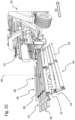
- the ejected cuboid bales or big bales can also optionally be rotated about a vertical axis, but for the sake of clarity in Figure 1A not shown, but in a schematic way based on the Figure 1B as well as the Figure 1C should be clarified.
- the direction of material flow 28 through the straw press 10 is drawn again here, which is only drawn as a simple box in order to be able to better illustrate the material flow 28 and the subsequent handling steps to which the bales conveyed backwards out of the straw press 10 are subjected.
- the pressed and tied cuboid bales 36 are conveyed backwards out of the housing 18 in the direction of material flow 28 and transferred to the chute 32 located at the rear of the housing 18, which ensures that the bales are conveyed further in the direction of the arrow (cf. Figure 1B ).
- bales 36 Only in the area behind the chute 32 are the bales 36 (in Figure 1C not shown) by means of a support table 42 that can be rotated about an approximately vertical axis 40 with an inclined ramp 44 adjoining it at the edge, first rotated by 90° about the vertical axis 40 and then pushed backwards in this rotated position (cf. the further material flow arrow in Figure 1D ).
- FIG. 2A to 2D again show the material flow of a cuboid bale pushed out at the rear of the crop press 10 .
- the one located at the back of the crop press 10 is shown in each case Chute 32, which is followed by an attached conveying and/or storage device 38 for ejecting finished bales or big bales wrapped with twine.
- This conveying and/or depositing device 38 has a vertical axis 40 (cf. Figure 2A ) rotatable support table 42 with an inclined ramp 44 adjoining it laterally for the controlled depositing of bales on the ground.
- the rotatable support table 42 is also assigned a pushing device 46 for pushing bales or large bales on the support table 42 towards the inclined ramp 44 .
- the support table 42 is formed by a plurality of square tubes connected to one another, on the flat tops of which bales can slide by means of the sliding device 46 .
- the flat tops of the square tubes form a support surface 50 of the support table.
- the sliding device 46 can include in particular a push bar 48, which is movable in the horizontal direction and thus also parallel to the support surface 50 of the support table 42 at a small distance from it. With this push bar 48 of the pusher 46, the bales can be transported in the direction of the sloping ramp 44 and deposited on the ground before there.
- the support table 42 can be moved about the vertical axis of rotation 40, it is rotatably mounted on a frame section or chassis which is coupled to the crop press 10 and suspended from the rear thereof. Like it the Figures 2A to 3C can be seen, is located approximately in the middle below the support table 42 a twin support wheel 52 rolling on the ground, whereby all the resulting weight forces are easily supported on the ground and the articulated connection to the straw press 10 can be mechanically relieved.
- the frame section with the support table 42 rotatably mounted on it is foldably suspended at the rear of the straw press 10 and in this way forms a movable part of the straw press 10.
- the frame section remains firmly connected to the straw press 10, whereby it is in use (cf. Figures 2A to 3C ) can be designed in the manner shown as a trailer or as a trailer-like element that is supported rolling on the support wheel 52 on the ground.
- the inclined ramp 44 located on one long side of the rotatable support table 42 can be variably adjustable in its angle to the support surface 50 of the support table 42 in order to compensate for different ground conditions or to be able to set different distances between a lower edge of the inclined ramp 44 and the ground.
- the inclined ramp 44 can comprise a plurality of rotatable rollers 54 which together form a conveying plane for the bales which can roll on this inclined conveying plane.
- the rollers 54 of the inclined ramp 44 can each be passively mounted, whereby they each rotate about horizontal axes of rotation, these axes of rotation lying approximately transversely to the conveying and pushing-off direction of the bales rolling on them, so that they optimally support the conveying or rolling movement can.
- the Figure 2A shows the conveying and/or depositing device 38 with the rotatable support table 42 in a first end position, in which the narrow sides of the support table 42 are aligned transversely to the direction of travel or longitudinal direction of the crop press 10, while the long sides of the support table 42 are aligned parallel to the direction of travel and at the same time align with the long sides of the crop baler 10.
- This first end position forms the standard case, in which the bales are discharged in the usual way from the crop press 10 with their narrow sides pointing backwards (cf. Figure 2B ), so that their longer sides are aligned parallel to the direction of travel of the crop press 10.
- the inclined ramp 44 is also aligned parallel to the direction of travel or longitudinal direction of the crop press 10 and is located on a longitudinal side of the support table 42 of the conveying and/or depositing device 38 (cf. Figure 2A and Figure 2B ).
- the rear view of the 2D clarifies with hatching a cuboid bale 36 lying on the support surface 50, the longitudinal sides of which are arranged parallel to the direction of travel 34.
- FIGs 3A to 3C illustrate a second end position of the support table 42, which is formed in that the longitudinal sides of the support table 42 are transverse to the direction of travel 34 or in the longitudinal direction of the crop press 10, and that the narrow sides of the support table 42 are aligned parallel to the direction of travel 34 and are aligned with the long sides of the crop press 10 (cf. Figure 3A ).
- the inclined ramp 44 is aligned transversely to the direction of travel 34 or longitudinal direction of the straw baler 10 and is located at the rear of the conveyor and/or depositing device 38 or points in a direction opposite to the direction of travel 34 of the straw baler 10, so that the rotated bales 36 can be stored on the back.
- the thus rotated bales 36 are stored with their long sides transverse to the direction of travel 34 and opposite to this backwards over the inclined ramp 44, as the Figure 3B indicated in a schematic way.
- the support table 42 can be coupled to a motorized actuator (not shown) that can provide controlled rotation and reverse rotation and/or rotational movement between the two end positions.
- a motorized actuator (not shown) that can provide controlled rotation and reverse rotation and/or rotational movement between the two end positions.
- Such an actuator can, for example Figures 2A to 3C can rotate in the manner shown.
- Other actuators are also conceivable, for example hydraulically or pneumatically actuated adjusting cylinders, which are preferably arranged below the support table 42 and can rotate or pivot it in the desired manner.
- the sliding device 46 can preferably also be coupled to a motor-operated actuator which can ensure a controlled movement and return movement of the push bar 48 in the linear direction.
- Hydraulically or pneumatically actuated positioning cylinders for example, which can provide the required linear movement, are also suitable for this.
Landscapes
- Life Sciences & Earth Sciences (AREA)
- Environmental Sciences (AREA)
- Harvesting Machines For Specific Crops (AREA)
Claims (15)
- Presse agricole de produits en tige (10) destiné à presser des balles ou de grosses balles, en particulier en forme de parallélépipède rectangle, avec un dispositif de réception (20) destiné à recevoir de la récolte, avec un dispositif de pressage pour presser la récolte en balles (36) de taille définie et avec un dispositif de transport et/ou de dépôt (32, 38) qui est disposé en aval du dispositif de pressage et destiné à éjecter des balles finies et enveloppées de ficelle,dans laquelle le dispositif de transport et/ou de dépôt (38) présente une table de support (42) apte à être tournée autour d'un axe (40) à peu près vertical,caractérisée par le fait que la table de support (42) rotative du dispositif de transport et/ou de dépose (38) est suivie latéralement d'une rampe inclinée (44) pour déposer de manière contrôlée des balles (36) sur le sol,et qu'à la table de support (42) rotative est associé un dispositif à pousser (46) destiné à évacuer en poussant des balles (36) ou grosses balles situées sur la table de support (42) en direction de la rampe inclinée (44).
- Presse agricole de produits en tige (10), selon la revendication 1, dans laquelle le dispositif à pousser (46) comprend au moins une barre de poussée (48) qui peut être déplacée sur la table de support (42) dans la direction horizontale et/ou parallèlement à la surface de support (50) de celle-ci.
- Presse agricole de produits en tige (10) selon la revendication 1 ou 2, dans laquelle la table de support (42) est logée à rotation sur une section de châssis qui est couplée à la presse de produits en tige (10) et/ou attachée à l'arrière de la presse de produits en tige (10), dans laquelle la table de support (42) peut être déplacée ou tournée de 90° à peu près autour de l'axe vertical de rotation (40) en particulier entre deux positions extrêmes.
- Presse agricole de produits en tige (10) selon la revendication 3, dans laquelle la section de châssis est conçue en tant que remorque qui est attachée côté arrière sur la presse de produits en tige (10) et est couplée de manière amovible à celle-ci, dans laquelle au moins une roue d'appui (52) qui roule sur le sol est située en particulier au-dessous de la table de support (42).
- Presse agricole de produits en tige (10) selon la revendication 3 ou 4, dans laquelle la section de châssis est suspendue de manière pliable sur la face arrière de la presse de produits en tige (10) et forme une partie mobile de cette presse de produits en tige (10).
- Presse agricole de produits en tige (10) selon l'une quelconque des revendications 1 à 5, dans laquelle la rampe inclinée (44) située sur un grand ou petit côté de la table de support (42) rotative est réglable de manière variable dans son angle par rapport à la surface de support (50) de la table de support (42), et dans laquelle la rampe inclinée (44) comprend en particulier une pluralité de galets (54) qui forment ensemble un plan de convoyage pour les balles (36) qui peuvent rouler sur ce plan de convoyage.
- Presse agricole de produits en tige (10) selon l'une quelconque des revendications 1 à 6, dans laquelle les galets de la table de support (42) et/ou les galets (54) de la rampe inclinée (44) sont munis chacun de dispositifs d'entraînement pour pouvoir évacuer en poussant des balles (36) et pour pouvoir déposer celles-ci sur le sol.
- Presse agricole de produits en tige (10) selon l'une quelconque des revendications 1 à 7, dans laquelle la table de support (42) est couplée à un actionneur commandé par moteur qui peut assurer une rotation et une rotation inverse commandées et/ou un mouvement rotatif entre les deux positions extrêmes.
- Presse agricole de produits en tige (10) selon l'une quelconque des revendications 1 à 8, dans laquelle le dispositif à pousser (46) est couplé à un actionneur commandé par moteur qui peut assurer un mouvement et un mouvement de retour commandés de la barre de poussée (48) en direction linéaire.
- Procédé de dépôt de balles (36) ou de grosses balles, en particulier en forme de parallélépipède rectangle, qui ont été pressées à partir de récolte ramassée au sol au moyen d'une presse agricole de produit en tige (10), en particulier au moyen d'une presse agricole de produits en tige (10) selon l'une quelconque des revendications 1 à 9, dans lequel les balles (36), après qu'elles ont été pressées, sont évacuées par un dispositif de transport et/ou de dépôt (32, 38) disposé côté arrière sur la presse de produits en tige (10), y sont tournées autour d'un axe (40) à peu près vertical et sont transférées par poussée, au moyen d'un dispositif à pousser (46), à une rampe inclinée (44) et sont déposées de manière contrôlées sur le sol.
- Procédé selon la revendication 10, dans lequel les balles (36) sont tournées de 90° à peu près autour d'un axe (40) à peu près vertical et sont déposées sur le sol, leurs grands côtés étant transversaux à la direction de marche (34).
- Procédé selon la revendication 10 ou 11, dans lequel les balles (36) sont déposées via la rampe inclinée (44) disposée côté arrière sur la presse de produits en tige (10), dans une voie de circulation de la presse de produits en tige (10).
- Procédé selon l'une quelconque des revendications 10 à 12, dans lequel la table de support (42) de la presse de produits en tige (10) est tournée de 90° à peu près à chaque fois qu'une balle (36) se trouve sur celle-ci.
- Procédé selon la revendication 13, dans lequel, suite à un mouvement de rotation de la table de support (42) avec une balle (36) se trouvant sur celle-ci, la barre de poussée (48) est activée et la balle (36) est évacuée par poussée vers l'arrière via la rampe inclinée (44) et est déposée sur le sol.
- Procédé selon la revendication 14, dans lequel, après qu'une balle (36) a été évacuée par poussée de la table de support (42) au moyen de la barre de poussée (48), la table de support (42) est à nouveau tournée en arrière afin de pouvoir recevoir une autre balle (36) qui est transportée hors de la presse de produits en tige (10).
Applications Claiming Priority (1)
| Application Number | Priority Date | Filing Date | Title |
|---|---|---|---|
| DE102020126480.1A DE102020126480A1 (de) | 2020-10-09 | 2020-10-09 | Landwirtschaftliche Halmgutpresse und Verfahren zur Ablage von Ballen aus gepressten Halmgut |
Publications (2)
| Publication Number | Publication Date |
|---|---|
| EP3981245A1 EP3981245A1 (fr) | 2022-04-13 |
| EP3981245B1 true EP3981245B1 (fr) | 2023-06-07 |
Family
ID=77897545
Family Applications (1)
| Application Number | Title | Priority Date | Filing Date |
|---|---|---|---|
| EP21198191.5A Active EP3981245B1 (fr) | 2020-10-09 | 2021-09-22 | Presse agricole pour fourrage et procédé de dépôt des balles de fourrage comprimé |
Country Status (2)
| Country | Link |
|---|---|
| EP (1) | EP3981245B1 (fr) |
| DE (1) | DE102020126480A1 (fr) |
Families Citing this family (1)
| Publication number | Priority date | Publication date | Assignee | Title |
|---|---|---|---|---|
| EP4458131A1 (fr) | 2023-04-26 | 2024-11-06 | Georg Rubenbauer | Presse agricole, notamment presse à balles rondes |
Family Cites Families (8)
| Publication number | Priority date | Publication date | Assignee | Title |
|---|---|---|---|---|
| US2853171A (en) | 1957-02-15 | 1958-09-23 | Matthews Ozias | Bale turner |
| US3161008A (en) | 1963-04-16 | 1964-12-15 | Sperry Rand Corp | Discharge device |
| US3243028A (en) | 1964-04-30 | 1966-03-29 | Int Harvester Co | Bale turner and aligner |
| US4162135A (en) | 1977-12-01 | 1979-07-24 | Sperry Rand Corporation | Quarter bale turning apparatus |
| US5024152A (en) | 1990-05-14 | 1991-06-18 | Hay & Forage Industries | Quarter turn bale discharge apparatus |
| US5560191A (en) * | 1995-06-05 | 1996-10-01 | Finney; Denzel R. | Jumbo bale rotating table for a hay baler |
| US6033172A (en) * | 1999-02-19 | 2000-03-07 | Maize Corporation | Bale turning apparatus |
| DE102009039268B4 (de) | 2009-08-28 | 2013-02-21 | Müthing GmbH & Co. KG | Vorrichtung zu Reinigung einer Ballenpresse |
-
2020
- 2020-10-09 DE DE102020126480.1A patent/DE102020126480A1/de active Pending
-
2021
- 2021-09-22 EP EP21198191.5A patent/EP3981245B1/fr active Active
Also Published As
| Publication number | Publication date |
|---|---|
| EP3981245A1 (fr) | 2022-04-13 |
| DE102020126480A1 (de) | 2022-04-14 |
Similar Documents
| Publication | Publication Date | Title |
|---|---|---|
| EP2067399B1 (fr) | Arrangement de réglage de la position d'un tambour ramasseur et d'un élément presseur d'une moissonneuse agricole | |
| DE69817577T2 (de) | Wickelmaschine | |
| DE602004012495T2 (de) | Erntegutaufnahmevorrichtung und Erntefahrzeug | |
| DE69522816T2 (de) | Kombinierte presse- und wickelgerät für zylindrische körper | |
| DE1160229C2 (de) | Verfahren zum aufladen, pressen und horizontalen verteilen von landwirtschaftlichem halm- und blattgut auf einen transportwagen und landwirtschaftliches transportfahrzeug zur durchfuehrung dieses verfahrens | |
| EP1133913A2 (fr) | Presse à balles rondes | |
| DE1855930U (de) | Maschine zum aufladen, horizontalen verteilen und pressen von massenguetern auf einer fahrbaren ladeflaeche. | |
| DE102011109899A1 (de) | Landwirtschaftliche Rundballenpresse | |
| EP1604565A1 (fr) | Système de pose pour balles | |
| DE2626263C2 (de) | Wickelpresse zum Herstellen von Ballen aus landwirtschaftlichem Halmgut, insbesondere Heu | |
| DE3443719A1 (de) | Ballenpresse | |
| WO1994004020A2 (fr) | Presse-balles automobile pour plantes cultivees dans les champs | |
| DE102011109891A1 (de) | Landwirtschaftliche Rundballenpresse | |
| EP2556741B1 (fr) | Presse à balles rondes agricole | |
| DE102007036293A1 (de) | Landwirtschaftliche Ballenpresse | |
| EP3981245B1 (fr) | Presse agricole pour fourrage et procédé de dépôt des balles de fourrage comprimé | |
| DE69904714T2 (de) | Rundballenpresse mit integrierter wickelvorrichtung | |
| DE2810676A1 (de) | Dosiervorrichtung fuer landwirtschaftliche erntegueter | |
| EP4458131A1 (fr) | Presse agricole, notamment presse à balles rondes | |
| DE69836232T2 (de) | Kombinierte Press- und Wickelvorrichtung | |
| EP3959961B1 (fr) | Presse pour produits de récolte à tiges pourvu de module de coupe amovible et procédé de manipulation d'un tel module de coupe amovible | |
| EP1932418B1 (fr) | Dispositif accessoire de récolte destiné à ramasser les récoltes au sol | |
| DE4312991A1 (de) | Verfahren und Presse zum Bilden quaderförmiger Preßballen aus landwirtschaftlichem Erntegut | |
| EP2556743B1 (fr) | Presse à balles rondes agricole | |
| EP4282248A1 (fr) | Presse à balles rondes |
Legal Events
| Date | Code | Title | Description |
|---|---|---|---|
| PUAI | Public reference made under article 153(3) epc to a published international application that has entered the european phase |
Free format text: ORIGINAL CODE: 0009012 |
|
| STAA | Information on the status of an ep patent application or granted ep patent |
Free format text: STATUS: THE APPLICATION HAS BEEN PUBLISHED |
|
| AK | Designated contracting states |
Kind code of ref document: A1 Designated state(s): AL AT BE BG CH CY CZ DE DK EE ES FI FR GB GR HR HU IE IS IT LI LT LU LV MC MK MT NL NO PL PT RO RS SE SI SK SM TR |
|
| STAA | Information on the status of an ep patent application or granted ep patent |
Free format text: STATUS: REQUEST FOR EXAMINATION WAS MADE |
|
| 17P | Request for examination filed |
Effective date: 20220919 |
|
| RBV | Designated contracting states (corrected) |
Designated state(s): AL AT BE BG CH CY CZ DE DK EE ES FI FR GB GR HR HU IE IS IT LI LT LU LV MC MK MT NL NO PL PT RO RS SE SI SK SM TR |
|
| GRAP | Despatch of communication of intention to grant a patent |
Free format text: ORIGINAL CODE: EPIDOSNIGR1 |
|
| STAA | Information on the status of an ep patent application or granted ep patent |
Free format text: STATUS: GRANT OF PATENT IS INTENDED |
|
| INTG | Intention to grant announced |
Effective date: 20230217 |
|
| GRAS | Grant fee paid |
Free format text: ORIGINAL CODE: EPIDOSNIGR3 |
|
| GRAA | (expected) grant |
Free format text: ORIGINAL CODE: 0009210 |
|
| STAA | Information on the status of an ep patent application or granted ep patent |
Free format text: STATUS: THE PATENT HAS BEEN GRANTED |
|
| AK | Designated contracting states |
Kind code of ref document: B1 Designated state(s): AL AT BE BG CH CY CZ DE DK EE ES FI FR GB GR HR HU IE IS IT LI LT LU LV MC MK MT NL NO PL PT RO RS SE SI SK SM TR |
|
| REG | Reference to a national code |
Ref country code: GB Ref legal event code: FG4D Free format text: NOT ENGLISH |
|
| REG | Reference to a national code |
Ref country code: CH Ref legal event code: EP Ref country code: AT Ref legal event code: REF Ref document number: 1571857 Country of ref document: AT Kind code of ref document: T Effective date: 20230615 |
|
| REG | Reference to a national code |
Ref country code: DE Ref legal event code: R096 Ref document number: 502021000807 Country of ref document: DE |
|
| REG | Reference to a national code |
Ref country code: NL Ref legal event code: FP |
|
| REG | Reference to a national code |
Ref country code: LT Ref legal event code: MG9D |
|
| PG25 | Lapsed in a contracting state [announced via postgrant information from national office to epo] |
Ref country code: SE Free format text: LAPSE BECAUSE OF FAILURE TO SUBMIT A TRANSLATION OF THE DESCRIPTION OR TO PAY THE FEE WITHIN THE PRESCRIBED TIME-LIMIT Effective date: 20230607 Ref country code: NO Free format text: LAPSE BECAUSE OF FAILURE TO SUBMIT A TRANSLATION OF THE DESCRIPTION OR TO PAY THE FEE WITHIN THE PRESCRIBED TIME-LIMIT Effective date: 20230907 Ref country code: ES Free format text: LAPSE BECAUSE OF FAILURE TO SUBMIT A TRANSLATION OF THE DESCRIPTION OR TO PAY THE FEE WITHIN THE PRESCRIBED TIME-LIMIT Effective date: 20230607 |
|
| PG25 | Lapsed in a contracting state [announced via postgrant information from national office to epo] |
Ref country code: RS Free format text: LAPSE BECAUSE OF FAILURE TO SUBMIT A TRANSLATION OF THE DESCRIPTION OR TO PAY THE FEE WITHIN THE PRESCRIBED TIME-LIMIT Effective date: 20230607 Ref country code: LV Free format text: LAPSE BECAUSE OF FAILURE TO SUBMIT A TRANSLATION OF THE DESCRIPTION OR TO PAY THE FEE WITHIN THE PRESCRIBED TIME-LIMIT Effective date: 20230607 Ref country code: LT Free format text: LAPSE BECAUSE OF FAILURE TO SUBMIT A TRANSLATION OF THE DESCRIPTION OR TO PAY THE FEE WITHIN THE PRESCRIBED TIME-LIMIT Effective date: 20230607 Ref country code: HR Free format text: LAPSE BECAUSE OF FAILURE TO SUBMIT A TRANSLATION OF THE DESCRIPTION OR TO PAY THE FEE WITHIN THE PRESCRIBED TIME-LIMIT Effective date: 20230607 Ref country code: GR Free format text: LAPSE BECAUSE OF FAILURE TO SUBMIT A TRANSLATION OF THE DESCRIPTION OR TO PAY THE FEE WITHIN THE PRESCRIBED TIME-LIMIT Effective date: 20230908 |
|
| PG25 | Lapsed in a contracting state [announced via postgrant information from national office to epo] |
Ref country code: FI Free format text: LAPSE BECAUSE OF FAILURE TO SUBMIT A TRANSLATION OF THE DESCRIPTION OR TO PAY THE FEE WITHIN THE PRESCRIBED TIME-LIMIT Effective date: 20230607 |
|
| PG25 | Lapsed in a contracting state [announced via postgrant information from national office to epo] |
Ref country code: SK Free format text: LAPSE BECAUSE OF FAILURE TO SUBMIT A TRANSLATION OF THE DESCRIPTION OR TO PAY THE FEE WITHIN THE PRESCRIBED TIME-LIMIT Effective date: 20230607 |
|
| PG25 | Lapsed in a contracting state [announced via postgrant information from national office to epo] |
Ref country code: IS Free format text: LAPSE BECAUSE OF FAILURE TO SUBMIT A TRANSLATION OF THE DESCRIPTION OR TO PAY THE FEE WITHIN THE PRESCRIBED TIME-LIMIT Effective date: 20231007 |
|
| PG25 | Lapsed in a contracting state [announced via postgrant information from national office to epo] |
Ref country code: SM Free format text: LAPSE BECAUSE OF FAILURE TO SUBMIT A TRANSLATION OF THE DESCRIPTION OR TO PAY THE FEE WITHIN THE PRESCRIBED TIME-LIMIT Effective date: 20230607 Ref country code: SK Free format text: LAPSE BECAUSE OF FAILURE TO SUBMIT A TRANSLATION OF THE DESCRIPTION OR TO PAY THE FEE WITHIN THE PRESCRIBED TIME-LIMIT Effective date: 20230607 Ref country code: RO Free format text: LAPSE BECAUSE OF FAILURE TO SUBMIT A TRANSLATION OF THE DESCRIPTION OR TO PAY THE FEE WITHIN THE PRESCRIBED TIME-LIMIT Effective date: 20230607 Ref country code: PT Free format text: LAPSE BECAUSE OF FAILURE TO SUBMIT A TRANSLATION OF THE DESCRIPTION OR TO PAY THE FEE WITHIN THE PRESCRIBED TIME-LIMIT Effective date: 20231009 Ref country code: IS Free format text: LAPSE BECAUSE OF FAILURE TO SUBMIT A TRANSLATION OF THE DESCRIPTION OR TO PAY THE FEE WITHIN THE PRESCRIBED TIME-LIMIT Effective date: 20231007 Ref country code: EE Free format text: LAPSE BECAUSE OF FAILURE TO SUBMIT A TRANSLATION OF THE DESCRIPTION OR TO PAY THE FEE WITHIN THE PRESCRIBED TIME-LIMIT Effective date: 20230607 Ref country code: CZ Free format text: LAPSE BECAUSE OF FAILURE TO SUBMIT A TRANSLATION OF THE DESCRIPTION OR TO PAY THE FEE WITHIN THE PRESCRIBED TIME-LIMIT Effective date: 20230607 |
|
| PG25 | Lapsed in a contracting state [announced via postgrant information from national office to epo] |
Ref country code: PL Free format text: LAPSE BECAUSE OF FAILURE TO SUBMIT A TRANSLATION OF THE DESCRIPTION OR TO PAY THE FEE WITHIN THE PRESCRIBED TIME-LIMIT Effective date: 20230607 |
|
| REG | Reference to a national code |
Ref country code: DE Ref legal event code: R097 Ref document number: 502021000807 Country of ref document: DE |
|
| PLBE | No opposition filed within time limit |
Free format text: ORIGINAL CODE: 0009261 |
|
| STAA | Information on the status of an ep patent application or granted ep patent |
Free format text: STATUS: NO OPPOSITION FILED WITHIN TIME LIMIT |
|
| PG25 | Lapsed in a contracting state [announced via postgrant information from national office to epo] |
Ref country code: DK Free format text: LAPSE BECAUSE OF FAILURE TO SUBMIT A TRANSLATION OF THE DESCRIPTION OR TO PAY THE FEE WITHIN THE PRESCRIBED TIME-LIMIT Effective date: 20230607 |
|
| PG25 | Lapsed in a contracting state [announced via postgrant information from national office to epo] |
Ref country code: SI Free format text: LAPSE BECAUSE OF FAILURE TO SUBMIT A TRANSLATION OF THE DESCRIPTION OR TO PAY THE FEE WITHIN THE PRESCRIBED TIME-LIMIT Effective date: 20230607 |
|
| 26N | No opposition filed |
Effective date: 20240308 |
|
| PG25 | Lapsed in a contracting state [announced via postgrant information from national office to epo] |
Ref country code: LU Free format text: LAPSE BECAUSE OF NON-PAYMENT OF DUE FEES Effective date: 20230922 |
|
| P01 | Opt-out of the competence of the unified patent court (upc) registered |
Effective date: 20240424 |
|
| PG25 | Lapsed in a contracting state [announced via postgrant information from national office to epo] |
Ref country code: SI Free format text: LAPSE BECAUSE OF FAILURE TO SUBMIT A TRANSLATION OF THE DESCRIPTION OR TO PAY THE FEE WITHIN THE PRESCRIBED TIME-LIMIT Effective date: 20230607 Ref country code: LU Free format text: LAPSE BECAUSE OF NON-PAYMENT OF DUE FEES Effective date: 20230922 Ref country code: IT Free format text: LAPSE BECAUSE OF FAILURE TO SUBMIT A TRANSLATION OF THE DESCRIPTION OR TO PAY THE FEE WITHIN THE PRESCRIBED TIME-LIMIT Effective date: 20230607 Ref country code: MC Free format text: LAPSE BECAUSE OF FAILURE TO SUBMIT A TRANSLATION OF THE DESCRIPTION OR TO PAY THE FEE WITHIN THE PRESCRIBED TIME-LIMIT Effective date: 20230607 |
|
| REG | Reference to a national code |
Ref country code: IE Ref legal event code: MM4A |
|
| PG25 | Lapsed in a contracting state [announced via postgrant information from national office to epo] |
Ref country code: IE Free format text: LAPSE BECAUSE OF NON-PAYMENT OF DUE FEES Effective date: 20230922 |
|
| PG25 | Lapsed in a contracting state [announced via postgrant information from national office to epo] |
Ref country code: IE Free format text: LAPSE BECAUSE OF NON-PAYMENT OF DUE FEES Effective date: 20230922 |
|
| REG | Reference to a national code |
Ref country code: DE Ref legal event code: R082 Ref document number: 502021000807 Country of ref document: DE Representative=s name: BENNINGER, JOHANNES, DIPL.-ING., DE Ref country code: DE Ref legal event code: R082 Ref document number: 502021000807 Country of ref document: DE Representative=s name: DENNEMEYER & ASSOCIATES S.A., DE Ref country code: DE Ref legal event code: R082 Ref document number: 502021000807 Country of ref document: DE Representative=s name: DENNEMEYER & ASSOCIATES RECHTSANWALTSGESELLSCH, DE |
|
| PG25 | Lapsed in a contracting state [announced via postgrant information from national office to epo] |
Ref country code: BG Free format text: LAPSE BECAUSE OF FAILURE TO SUBMIT A TRANSLATION OF THE DESCRIPTION OR TO PAY THE FEE WITHIN THE PRESCRIBED TIME-LIMIT Effective date: 20230607 |
|
| PG25 | Lapsed in a contracting state [announced via postgrant information from national office to epo] |
Ref country code: BG Free format text: LAPSE BECAUSE OF FAILURE TO SUBMIT A TRANSLATION OF THE DESCRIPTION OR TO PAY THE FEE WITHIN THE PRESCRIBED TIME-LIMIT Effective date: 20230607 |
|
| REG | Reference to a national code |
Ref country code: CH Ref legal event code: PL |
|
| PG25 | Lapsed in a contracting state [announced via postgrant information from national office to epo] |
Ref country code: CH Free format text: LAPSE BECAUSE OF NON-PAYMENT OF DUE FEES Effective date: 20240930 |
|
| PG25 | Lapsed in a contracting state [announced via postgrant information from national office to epo] |
Ref country code: CY Free format text: LAPSE BECAUSE OF FAILURE TO SUBMIT A TRANSLATION OF THE DESCRIPTION OR TO PAY THE FEE WITHIN THE PRESCRIBED TIME-LIMIT; INVALID AB INITIO Effective date: 20210922 |
|
| PG25 | Lapsed in a contracting state [announced via postgrant information from national office to epo] |
Ref country code: HU Free format text: LAPSE BECAUSE OF FAILURE TO SUBMIT A TRANSLATION OF THE DESCRIPTION OR TO PAY THE FEE WITHIN THE PRESCRIBED TIME-LIMIT; INVALID AB INITIO Effective date: 20210922 |
|
| PGFP | Annual fee paid to national office [announced via postgrant information from national office to epo] |
Ref country code: DE Payment date: 20250919 Year of fee payment: 5 |
|
| PGFP | Annual fee paid to national office [announced via postgrant information from national office to epo] |
Ref country code: NL Payment date: 20250918 Year of fee payment: 5 |
|
| PGFP | Annual fee paid to national office [announced via postgrant information from national office to epo] |
Ref country code: BE Payment date: 20250918 Year of fee payment: 5 |
|
| PGFP | Annual fee paid to national office [announced via postgrant information from national office to epo] |
Ref country code: AT Payment date: 20251020 Year of fee payment: 5 Ref country code: FR Payment date: 20250922 Year of fee payment: 5 |
|
| REG | Reference to a national code |
Ref country code: DE Ref legal event code: R081 Ref document number: 502021000807 Country of ref document: DE Owner name: USINES CLAAS FRANCE S.A.S, ST. REMY, FR Free format text: FORMER OWNER: RUBENBAUER, GEORG, 95695 MAEHRING, DE Ref country code: DE Ref legal event code: R082 Ref document number: 502021000807 Country of ref document: DE Representative=s name: DENNEMEYER & ASSOCIATES S.A., DE Ref country code: DE Ref legal event code: R082 Ref document number: 502021000807 Country of ref document: DE Representative=s name: DENNEMEYER & ASSOCIATES RECHTSANWALTSGESELLSCH, DE |
|
| REG | Reference to a national code |
Ref country code: DE Ref legal event code: R082 Ref document number: 502021000807 Country of ref document: DE Representative=s name: DENNEMEYER & ASSOCIATES RECHTSANWALTSGESELLSCH, DE |
|
| PG25 | Lapsed in a contracting state [announced via postgrant information from national office to epo] |
Ref country code: TR Free format text: LAPSE BECAUSE OF FAILURE TO SUBMIT A TRANSLATION OF THE DESCRIPTION OR TO PAY THE FEE WITHIN THE PRESCRIBED TIME-LIMIT Effective date: 20230607 |
|
| REG | Reference to a national code |
Ref country code: BE Ref legal event code: PD Owner name: USINES CLAAS FRANCE S.A.S.; FR Free format text: DETAILS ASSIGNMENT: CHANGE OF OWNER(S), ASSIGNMENT; FORMER OWNER NAME: RUBENBAUER, GEORG Effective date: 20251015 |
|
| REG | Reference to a national code |
Ref country code: NL Ref legal event code: PD Owner name: USINES CLAAS FRANCE S.A.S.; FR Free format text: DETAILS ASSIGNMENT: CHANGE OF OWNER(S), ASSIGNMENT; FORMER OWNER NAME: RUBENBAUER, GEORG Effective date: 20260116 |