EP2556911A1 - Drahtelektrode zum Elektroerodieren und Herstellungsverfahren dafür - Google Patents
Drahtelektrode zum Elektroerodieren und Herstellungsverfahren dafür Download PDFInfo
- Publication number
- EP2556911A1 EP2556911A1 EP12178039A EP12178039A EP2556911A1 EP 2556911 A1 EP2556911 A1 EP 2556911A1 EP 12178039 A EP12178039 A EP 12178039A EP 12178039 A EP12178039 A EP 12178039A EP 2556911 A1 EP2556911 A1 EP 2556911A1
- Authority
- EP
- European Patent Office
- Prior art keywords
- metal
- wire
- core wire
- alloy layer
- electro
- Prior art date
- Legal status (The legal status is an assumption and is not a legal conclusion. Google has not performed a legal analysis and makes no representation as to the accuracy of the status listed.)
- Withdrawn
Links
- 238000003754 machining Methods 0.000 title claims abstract description 106
- 238000000034 method Methods 0.000 title claims abstract description 76
- 238000004519 manufacturing process Methods 0.000 title claims abstract description 12
- 229910052751 metal Inorganic materials 0.000 claims abstract description 127
- 239000002184 metal Substances 0.000 claims abstract description 127
- 229910045601 alloy Inorganic materials 0.000 claims abstract description 118
- 239000000956 alloy Substances 0.000 claims abstract description 118
- 238000009792 diffusion process Methods 0.000 claims abstract description 36
- 238000010438 heat treatment Methods 0.000 claims abstract description 29
- 238000007747 plating Methods 0.000 claims abstract description 16
- 229910001369 Brass Inorganic materials 0.000 claims description 32
- 239000010951 brass Substances 0.000 claims description 32
- 239000010949 copper Substances 0.000 claims description 32
- RYGMFSIKBFXOCR-UHFFFAOYSA-N Copper Chemical compound [Cu] RYGMFSIKBFXOCR-UHFFFAOYSA-N 0.000 claims description 29
- 238000007254 oxidation reaction Methods 0.000 claims description 28
- 229910052802 copper Inorganic materials 0.000 claims description 25
- 238000009713 electroplating Methods 0.000 claims description 11
- 229910052782 aluminium Inorganic materials 0.000 claims description 9
- ATJFFYVFTNAWJD-UHFFFAOYSA-N Tin Chemical compound [Sn] ATJFFYVFTNAWJD-UHFFFAOYSA-N 0.000 claims description 8
- XAGFODPZIPBFFR-UHFFFAOYSA-N aluminium Chemical compound [Al] XAGFODPZIPBFFR-UHFFFAOYSA-N 0.000 claims description 8
- 229910052718 tin Inorganic materials 0.000 claims description 8
- JBQYATWDVHIOAR-UHFFFAOYSA-N tellanylidenegermanium Chemical compound [Te]=[Ge] JBQYATWDVHIOAR-UHFFFAOYSA-N 0.000 claims description 7
- 229910000881 Cu alloy Inorganic materials 0.000 claims description 5
- 230000003746 surface roughness Effects 0.000 abstract description 19
- 239000011859 microparticle Substances 0.000 abstract description 3
- HCHKCACWOHOZIP-UHFFFAOYSA-N Zinc Chemical compound [Zn] HCHKCACWOHOZIP-UHFFFAOYSA-N 0.000 description 19
- 239000011701 zinc Substances 0.000 description 19
- 229910052725 zinc Inorganic materials 0.000 description 19
- 238000006243 chemical reaction Methods 0.000 description 17
- 238000005520 cutting process Methods 0.000 description 17
- 150000002739 metals Chemical class 0.000 description 12
- TVZPLCNGKSPOJA-UHFFFAOYSA-N copper zinc Chemical compound [Cu].[Zn] TVZPLCNGKSPOJA-UHFFFAOYSA-N 0.000 description 11
- 230000008016 vaporization Effects 0.000 description 11
- 238000009834 vaporization Methods 0.000 description 11
- 239000012634 fragment Substances 0.000 description 9
- 238000009966 trimming Methods 0.000 description 8
- 239000000463 material Substances 0.000 description 5
- 239000007788 liquid Substances 0.000 description 4
- QVGXLLKOCUKJST-UHFFFAOYSA-N atomic oxygen Chemical compound [O] QVGXLLKOCUKJST-UHFFFAOYSA-N 0.000 description 3
- 230000003647 oxidation Effects 0.000 description 3
- 229910052760 oxygen Inorganic materials 0.000 description 3
- 239000001301 oxygen Substances 0.000 description 3
- 239000000843 powder Substances 0.000 description 3
- 238000005491 wire drawing Methods 0.000 description 3
- 230000002378 acidificating effect Effects 0.000 description 2
- 230000000052 comparative effect Effects 0.000 description 2
- 238000005238 degreasing Methods 0.000 description 2
- 230000000694 effects Effects 0.000 description 2
- 238000005259 measurement Methods 0.000 description 2
- 230000008018 melting Effects 0.000 description 2
- 238000002844 melting Methods 0.000 description 2
- 230000000087 stabilizing effect Effects 0.000 description 2
- 238000005406 washing Methods 0.000 description 2
- 238000004804 winding Methods 0.000 description 2
- 230000037303 wrinkles Effects 0.000 description 2
- ZOKXTWBITQBERF-UHFFFAOYSA-N Molybdenum Chemical compound [Mo] ZOKXTWBITQBERF-UHFFFAOYSA-N 0.000 description 1
- BQCADISMDOOEFD-UHFFFAOYSA-N Silver Chemical compound [Ag] BQCADISMDOOEFD-UHFFFAOYSA-N 0.000 description 1
- 238000007792 addition Methods 0.000 description 1
- 230000015572 biosynthetic process Effects 0.000 description 1
- 239000008367 deionised water Substances 0.000 description 1
- 229910021641 deionized water Inorganic materials 0.000 description 1
- 229910003460 diamond Inorganic materials 0.000 description 1
- 239000010432 diamond Substances 0.000 description 1
- 238000005516 engineering process Methods 0.000 description 1
- 238000004880 explosion Methods 0.000 description 1
- 238000009499 grossing Methods 0.000 description 1
- 239000000155 melt Substances 0.000 description 1
- 238000012986 modification Methods 0.000 description 1
- 230000004048 modification Effects 0.000 description 1
- 229910052709 silver Inorganic materials 0.000 description 1
- 239000004332 silver Substances 0.000 description 1
- 238000006467 substitution reaction Methods 0.000 description 1
- WFKWXMTUELFFGS-UHFFFAOYSA-N tungsten Chemical compound [W] WFKWXMTUELFFGS-UHFFFAOYSA-N 0.000 description 1
- XLYOFNOQVPJJNP-UHFFFAOYSA-N water Chemical compound O XLYOFNOQVPJJNP-UHFFFAOYSA-N 0.000 description 1
Images

Classifications
-
- B—PERFORMING OPERATIONS; TRANSPORTING
- B23—MACHINE TOOLS; METAL-WORKING NOT OTHERWISE PROVIDED FOR
- B23H—WORKING OF METAL BY THE ACTION OF A HIGH CONCENTRATION OF ELECTRIC CURRENT ON A WORKPIECE USING AN ELECTRODE WHICH TAKES THE PLACE OF A TOOL; SUCH WORKING COMBINED WITH OTHER FORMS OF WORKING OF METAL
- B23H7/00—Processes or apparatus applicable to both electrical discharge machining and electrochemical machining
- B23H7/02—Wire-cutting
- B23H7/08—Wire electrodes
-
- B—PERFORMING OPERATIONS; TRANSPORTING
- B23—MACHINE TOOLS; METAL-WORKING NOT OTHERWISE PROVIDED FOR
- B23H—WORKING OF METAL BY THE ACTION OF A HIGH CONCENTRATION OF ELECTRIC CURRENT ON A WORKPIECE USING AN ELECTRODE WHICH TAKES THE PLACE OF A TOOL; SUCH WORKING COMBINED WITH OTHER FORMS OF WORKING OF METAL
- B23H7/00—Processes or apparatus applicable to both electrical discharge machining and electrochemical machining
- B23H7/22—Electrodes specially adapted therefor or their manufacture
-
- B—PERFORMING OPERATIONS; TRANSPORTING
- B23—MACHINE TOOLS; METAL-WORKING NOT OTHERWISE PROVIDED FOR
- B23H—WORKING OF METAL BY THE ACTION OF A HIGH CONCENTRATION OF ELECTRIC CURRENT ON A WORKPIECE USING AN ELECTRODE WHICH TAKES THE PLACE OF A TOOL; SUCH WORKING COMBINED WITH OTHER FORMS OF WORKING OF METAL
- B23H7/00—Processes or apparatus applicable to both electrical discharge machining and electrochemical machining
- B23H7/22—Electrodes specially adapted therefor or their manufacture
- B23H7/24—Electrode material
-
- C—CHEMISTRY; METALLURGY
- C22—METALLURGY; FERROUS OR NON-FERROUS ALLOYS; TREATMENT OF ALLOYS OR NON-FERROUS METALS
- C22C—ALLOYS
- C22C9/00—Alloys based on copper
-
- C—CHEMISTRY; METALLURGY
- C23—COATING METALLIC MATERIAL; COATING MATERIAL WITH METALLIC MATERIAL; CHEMICAL SURFACE TREATMENT; DIFFUSION TREATMENT OF METALLIC MATERIAL; COATING BY VACUUM EVAPORATION, BY SPUTTERING, BY ION IMPLANTATION OR BY CHEMICAL VAPOUR DEPOSITION, IN GENERAL; INHIBITING CORROSION OF METALLIC MATERIAL OR INCRUSTATION IN GENERAL
- C23C—COATING METALLIC MATERIAL; COATING MATERIAL WITH METALLIC MATERIAL; SURFACE TREATMENT OF METALLIC MATERIAL BY DIFFUSION INTO THE SURFACE, BY CHEMICAL CONVERSION OR SUBSTITUTION; COATING BY VACUUM EVAPORATION, BY SPUTTERING, BY ION IMPLANTATION OR BY CHEMICAL VAPOUR DEPOSITION, IN GENERAL
- C23C28/00—Coating for obtaining at least two superposed coatings either by methods not provided for in a single one of groups C23C2/00 - C23C26/00 or by combinations of methods provided for in subclasses C23C and C25C or C25D
-
- C—CHEMISTRY; METALLURGY
- C23—COATING METALLIC MATERIAL; COATING MATERIAL WITH METALLIC MATERIAL; CHEMICAL SURFACE TREATMENT; DIFFUSION TREATMENT OF METALLIC MATERIAL; COATING BY VACUUM EVAPORATION, BY SPUTTERING, BY ION IMPLANTATION OR BY CHEMICAL VAPOUR DEPOSITION, IN GENERAL; INHIBITING CORROSION OF METALLIC MATERIAL OR INCRUSTATION IN GENERAL
- C23C—COATING METALLIC MATERIAL; COATING MATERIAL WITH METALLIC MATERIAL; SURFACE TREATMENT OF METALLIC MATERIAL BY DIFFUSION INTO THE SURFACE, BY CHEMICAL CONVERSION OR SUBSTITUTION; COATING BY VACUUM EVAPORATION, BY SPUTTERING, BY ION IMPLANTATION OR BY CHEMICAL VAPOUR DEPOSITION, IN GENERAL
- C23C28/00—Coating for obtaining at least two superposed coatings either by methods not provided for in a single one of groups C23C2/00 - C23C26/00 or by combinations of methods provided for in subclasses C23C and C25C or C25D
- C23C28/02—Coating for obtaining at least two superposed coatings either by methods not provided for in a single one of groups C23C2/00 - C23C26/00 or by combinations of methods provided for in subclasses C23C and C25C or C25D only coatings only including layers of metallic material
-
- C—CHEMISTRY; METALLURGY
- C23—COATING METALLIC MATERIAL; COATING MATERIAL WITH METALLIC MATERIAL; CHEMICAL SURFACE TREATMENT; DIFFUSION TREATMENT OF METALLIC MATERIAL; COATING BY VACUUM EVAPORATION, BY SPUTTERING, BY ION IMPLANTATION OR BY CHEMICAL VAPOUR DEPOSITION, IN GENERAL; INHIBITING CORROSION OF METALLIC MATERIAL OR INCRUSTATION IN GENERAL
- C23C—COATING METALLIC MATERIAL; COATING MATERIAL WITH METALLIC MATERIAL; SURFACE TREATMENT OF METALLIC MATERIAL BY DIFFUSION INTO THE SURFACE, BY CHEMICAL CONVERSION OR SUBSTITUTION; COATING BY VACUUM EVAPORATION, BY SPUTTERING, BY ION IMPLANTATION OR BY CHEMICAL VAPOUR DEPOSITION, IN GENERAL
- C23C28/00—Coating for obtaining at least two superposed coatings either by methods not provided for in a single one of groups C23C2/00 - C23C26/00 or by combinations of methods provided for in subclasses C23C and C25C or C25D
- C23C28/02—Coating for obtaining at least two superposed coatings either by methods not provided for in a single one of groups C23C2/00 - C23C26/00 or by combinations of methods provided for in subclasses C23C and C25C or C25D only coatings only including layers of metallic material
- C23C28/021—Coating for obtaining at least two superposed coatings either by methods not provided for in a single one of groups C23C2/00 - C23C26/00 or by combinations of methods provided for in subclasses C23C and C25C or C25D only coatings only including layers of metallic material including at least one metal alloy layer
-
- C—CHEMISTRY; METALLURGY
- C23—COATING METALLIC MATERIAL; COATING MATERIAL WITH METALLIC MATERIAL; CHEMICAL SURFACE TREATMENT; DIFFUSION TREATMENT OF METALLIC MATERIAL; COATING BY VACUUM EVAPORATION, BY SPUTTERING, BY ION IMPLANTATION OR BY CHEMICAL VAPOUR DEPOSITION, IN GENERAL; INHIBITING CORROSION OF METALLIC MATERIAL OR INCRUSTATION IN GENERAL
- C23C—COATING METALLIC MATERIAL; COATING MATERIAL WITH METALLIC MATERIAL; SURFACE TREATMENT OF METALLIC MATERIAL BY DIFFUSION INTO THE SURFACE, BY CHEMICAL CONVERSION OR SUBSTITUTION; COATING BY VACUUM EVAPORATION, BY SPUTTERING, BY ION IMPLANTATION OR BY CHEMICAL VAPOUR DEPOSITION, IN GENERAL
- C23C28/00—Coating for obtaining at least two superposed coatings either by methods not provided for in a single one of groups C23C2/00 - C23C26/00 or by combinations of methods provided for in subclasses C23C and C25C or C25D
- C23C28/02—Coating for obtaining at least two superposed coatings either by methods not provided for in a single one of groups C23C2/00 - C23C26/00 or by combinations of methods provided for in subclasses C23C and C25C or C25D only coatings only including layers of metallic material
- C23C28/023—Coating for obtaining at least two superposed coatings either by methods not provided for in a single one of groups C23C2/00 - C23C26/00 or by combinations of methods provided for in subclasses C23C and C25C or C25D only coatings only including layers of metallic material only coatings of metal elements only
-
- C—CHEMISTRY; METALLURGY
- C25—ELECTROLYTIC OR ELECTROPHORETIC PROCESSES; APPARATUS THEREFOR
- C25D—PROCESSES FOR THE ELECTROLYTIC OR ELECTROPHORETIC PRODUCTION OF COATINGS; ELECTROFORMING; APPARATUS THEREFOR
- C25D5/00—Electroplating characterised by the process; Pretreatment or after-treatment of workpieces
- C25D5/48—After-treatment of electroplated surfaces
- C25D5/50—After-treatment of electroplated surfaces by heat-treatment
-
- C—CHEMISTRY; METALLURGY
- C25—ELECTROLYTIC OR ELECTROPHORETIC PROCESSES; APPARATUS THEREFOR
- C25D—PROCESSES FOR THE ELECTROLYTIC OR ELECTROPHORETIC PRODUCTION OF COATINGS; ELECTROFORMING; APPARATUS THEREFOR
- C25D7/00—Electroplating characterised by the article coated
- C25D7/06—Wires; Strips; Foils
- C25D7/0607—Wires
Definitions
- the present invention relates to an electrode wire for electro-discharge machining and a method for manufacturing the same.
- the present invention relates to an electrode wire for electro-discharge machining and a method for manufacturing the same, capable of reducing micro-particles generated when an electrode wire is subject to the electro-discharge machining and improving the machining speed and the surface roughness of a workpiece.
- the electrode wire 2 is inserted into a workpiece 1 through a start hole 7 which has been previously perforated through the workpiece 1.
- a high-frequency voltage is applied between the electrode wire 2 and an inner wall surface of the start hole 7 while the electrode wire 2 is being continuously inserted into the workpiece 1 in the perforation direction of the start hole 7, thereby generating arc between the electrode wire 2 and the inner wall surface of the start hole 7, so that the workpiece 1 is melted.
- melts are removed by using a machining liquid and the instantaneous vaporization power between the electrode wire 2 and the workpiece 1, so that the workpiece 1 can be machined in a desired shape.
- an electro-discharge machine includes a power supply, a wire transferring unit for electro-discharge machining, a workpiece transferring unit, and a machining liquid circulating unit.
- the workpiece transferring unit moves perpendicularly to the electrode wire 2 for electro-discharge machining.
- the electrode wire 2 for electro-discharge machining continuously reeled out of a supply reel 3 is hang on guide rollers 5 and 5' provided at both end portions of the workpiece 1, the electrode wire 2 is wound around a winding reel 4.
- a high frequency-voltage is applied between the workpiece 1 and the electrode wire 2 for electro-discharge machining through the power supply 6 to perform a cutting machining process, and deionized water is supplied to a machining region as a machining liquid in order to discharge heat emitted in the cutting machining process.
- the efficiency of the electro-discharge machining especially, the machining speed, significantly depends on machining parameters such as the feeding speed of the machining liquid, machining current density, and the shape and frequency of the machining voltage, and the efficiency of the electro-discharge machining can be improved by adjusting the machining parameters.
- Pure copper has been used in a conventional technology since the pure copper has high electrical conductivity and facilities a fine wire process due to a high elongation property.
- a pure copper line represents a low tensile strength in the electro-discharge machining, the pure copper may be easily disconnected.
- a high tensile strength cannot be applied to the copper line, so that vibration of the electrode wire 2 cannot be controlled, thereby resulting in an inferior machining accuracy.
- the copper wire represents a relatively slower machining speed. Therefore, a high strength wire such as a molybdenum wire or a tungsten wire has been used for a special application of high machining precision.
- a brass electrode wire such as a brass wire including copper and zinc in a weight ratio of 65%:35%, has been developed for the general purpose of wire electro-discharge machining.
- the brass electrode wire When comparing with a pure copper wire, the brass electrode wire has a tensile strength which is at least twice greater than the tensile strength of the copper wire, and more improves discharge stability and instantaneous vaporization power due to zinc which is an alloy component of the brass electrode wire. Accordingly, when comparing with the pure copper wire, the brass electrode wire improves the machining speed and the machining precision.
- an advanced brass electrode wire has been developed by adding a small amount of Al, Si, and the like to the brass electrode wire, so that the tensile strength and the machining speed of the brass electrode wire can be improved.
- the machining speed may be increased.
- the zinc content is more than 40 weight% in the brass alloy, a weak brittle phase ⁇ is formed, so that a drawing process may be difficult when a fine wire is formed.
- the inventor of the present invention has suggested the structure of an electrode wire in Korea Patent Registration No. 10-518727 , in which the electrode wire includes a core wire including a first metal including copper, an alloy layer, which is formed from an outer portion of the core wire toward the center of the core wire by diffusing the component of a second metal to the first metal through the mutual diffusion reaction between the first and second metals at the boundary region of the core wire, an alloy plated layer, which is formed on the core wire by diffusing the component of the first metal to the second metal through the mutual diffusion reaction between the first and second metals, and a plating layer, which is formed on the alloy plated layer and includes the second metal having a vaporization temperature lower than that of the first metal constituting the core wire.
- the alloy plated layer is formed on the core wire through the mutual diffusion reaction between the first and second metals, so that the alloy plated layer represents the highest hardness and the lowest elongate percentage among the layers.
- the alloy plated layer and the plating layer have cracks appearing perpendicularly to the longitudinal direction of the electrode wire.
- an electrode wire including a core wire including a first metal including copper, an alloy layer, which is formed from an outer portion of the core wire toward the center of the core wire by diffusing the component of a second metal to the first metal through the mutual diffusion reaction between the first and second metals at the boundary region of the core wire, and an alloy plated layer, which is formed on the core wire by diffusing the component of the first metal to the second metal through the mutual diffusion reaction between the first and second metals.
- the alloy plated layer is formed on the core wire through the mutual diffusion reaction between the first metal and the second metal having a vaporization temperature lower than that of the first metal to represent the hardness higher than that of the core wire and the elongation percentage lower than that of the core wire.
- the alloy plated layer has cracks appearing perpendicularly to the longitudinal direction of the electrode wire.
- the first metal includes copper, brass, or a copper alloy
- the second metal includes zinc, aluminum, tin, or the alloy thereof.
- the inventor of the present invention has suggested a method for manufacturing an electrode wire for electro-discharge machining in Korea Patent Registration No. 10-518731 , in which the method includes preparing an intermediate wire rode, which serves as a core wire, includes a first metal including copper, and has a first diameter, forming an alloy layer, which represents the hardness higher than those of the first and second metals and the elongation percentage lower than those of the first and second metals, on an outer portion of the core wire through the mutual diffusion reaction between the first and second metals by passing the core wire including the first metal through a plating bath containing the second metal melted therein and having a vaporization temperature lower than that of the first metal and forming a plating layer including the second metal on the alloy layer, allowing cracks to appear on the alloy layer and the plating layer due to the higher hardness and the lower elongation percentage of the alloy layer by drawing the intermediate wire rod having the alloy and plating layers so that the intermediate wire rod has a second diameter, and stabilizing a mechanical characteristic of
- the core wire is passed through the plating bath for one second to ten seconds at a temperature of about 400°C to about 500 °C.
- the fist metal includes copper, brass, or a copper alloy
- the second metal includes zinc, aluminum, tin or the alloy thereof.
- the inventor of the present invention has suggested a method for manufacturing an electrode wire for electro-discharge machining in Korea Patent Registration No. 10-518733 , in which the method includes preparing an intermediate wire rode, which serves as a core wire, includes a first metal including copper, and has a first diameter, forming an alloy plated layer, which represents the hardness higher than those of the first and second metals and the elongation percentage lower than those of the first and second metals, on an outer portion of the core wire through the mutual diffusion reaction between the first and second metals by passing the core wire including the first metal through a plating bath containing the second metal melted therein and having a vaporization temperature lower than that of the first metal, allowing cracks to appear on the alloy plated layer due to the higher hardness and the lower elongation percentage of the alloy layer by drawing the intermediate wire rod having the alloy plated layer so that the intermediate wire rod has a second diameter, and stabilizing a mechanical characteristic of a fine wire by performing a heat treatment process with respect to the fine wire
- an electrode wire having an alloy layer including copper-zinc grain fragments is formed through the mutual diffusion reaction with a core wire metal including copper performed due to the melted zinc and applied heat, so that the machining speed can be improved.
- the brass core wire is strengthened, so that an alloy plated layer provided at an outer portion of the core wire may be easily fragmented, thereby producing a great amount of micro-particles in electro-discharge machining.
- an object of the present invention is to prevent an interfacial surface from being created on an electrode wire for electro-discharge machining by performing a heat treatment process after an electroplating process and a fine wire drawing process and to form a corrugation around the electrode wire.
- the electrode wire for electro-discharge machining has a smooth surface without the interfacial surface and the corrugation is formed on the surface of the electrode wire in a longitudinal direction of the electrode wire.
- Another object of the present invention is to provide an electrode wire for electro-discharge machining, capable of forming an alloy layer through a heat treatment process for a plated layer at a temperature of 60°C to 490°C, and manufacturing the electrode wire for electro-discharge machining having a corrugation on the surface of the alloy layer while maintaining the tensile strength in the range of 400 N/mm 2 to 1100 N/mm 2 , thereby basically preventing grain fragments from being created due to cracks, and improving the machining speed and the surface roughness of a workpiece according to the increase of the surface area due to the formed corrugation while significantly reducing micro-powders.
- Another object of the present invention is to provide an electrode wire for electro-discharge machining and a method for fabricating the same, capable of forming an alloy layer and an oxidization layer on the electrode wire for the electro-discharge machining by performing a heat treatment process with respect to the electrode wire for the electro-discharge machining without the interfacial surface at an oxidization atmosphere employing a temperature of 60°C to 490°C , thereby maximizing the machining speed and the surface roughness of the workpiece.
- an interfacial surface can be basically prevented from being created on the surface of the electrode wire having the alloy layer, and an oxidization layer is formed on the surface of the electrode wire having the alloy layer through the heat treatment process if necessary, thereby improving the surface roughness of the workpiece when performing the electro-discharge machining, and preventing micro-powders of the electrode wire while rapidly maintaining the machining speed.
- Still another object of the present invention is to provide an eco-friendly electrode wire capable of improving the precision of the electro-discharge machining and reducing micro-powders.
- an electrode wire for electro-discharge machining including a core wire including a first metal, a first alloy layer formed at a boundary surface of the core wire and a second metal through mutual diffusion between the second metal, which is plated on an outer surface of the core wire, and the core wire, and a second alloy layer formed at an outer portion of the first alloy layer through diffusion of the first metal toward the second metal.
- the second alloy layer is provided on a surface thereof with a corrugation having a predetermined pattern.
- the core wire, the first alloy layer, and the second alloy layer are formed without cracks.
- the electrode wire has a tensile strength in a range of about 400 N/mm 2 t01100N/mm 2 .
- the corrugation having the predetermined pattern formed on the second alloy layer is formed by an oxidization layer.
- the first metal includes one of copper (Cu), brass, and a copper alloy
- the second metal includes one of zinc (Zn), aluminum (Al), tin (Sn), and an alloy thereof.
- a method for manufacturing an electrode wire for electro-discharge machining includes preparing a wire rod, which includes a first metal and has a first diameter, as a core wire, plating a second metal on the core wire, performing a fine wire process for the core wire plated with the second metal so that the core wire has a second diameter, while forming a corrugation having a predetermined pattern on a surface of the core wire having the second diameter, and performing a heat treatment process to form a first alloy layer at a boundary surface between the core wire and the second metal through a mutual diffusion between the core wire and the second metal, and a second alloy layer at an outer portion of the first alloy layer through diffusion of the first metal toward the second metal.
- a method for manufacturing an electrode wire for electro-discharge machining includes preparing a wire rod, which includes a first metal and has a first diameter, as a core wire, plating a second metal on the core wire, performing a fine wire process for the core wire plated with the second metal so that the core wire has a second diameter, performing a heat treatment process to form a first alloy layer at a boundary surface between the core wire and the second metal through a mutual diffusion between the core wire and the second metal, and a second alloy layer at an outer portion of the first alloy layer through diffusion the first metal toward the second metal, and forming an oxidization layer on a surface of the second alloy layer while forming a corrugation having a predetermined pattern on a surface of the oxidization layer.
- the heat treatment process is performed for one hour to 120 hours at a temperature of 60°C to 490°C .
- the plating of the second metal on the core wire is performed through an electroplating scheme.
- the heat treatment process is performed at an oxidization atmosphere.
- the first metal may include pure copper (Cu), or brass including 63 to 67 weight% of copper (Cu) and 33 to 37 weight% of zinc (Zn), and the second metal may include zinc (Zn), aluminum (Al), tin (Sn), or the alloy thereof.
- the core wire having the first diameter is formed in the range of 0.9 mm to 1.2 mm, and the core wire having the second diameter is formed in the range of 0.07 mm to 0.35 mm.
- the first alloy layer is formed in the range of about 1 ⁇ m to about 3 ⁇ m
- the second alloy layer is formed in the range of about 2 ⁇ m to about 20 ⁇ m.
- the components of the second metal are diffused toward the first metal through the mutual diffusion reaction between the first metal and the second metal at the edge of the core wire rod, thereby forming the first alloy layer from the outer portion of the core wire toward the center of the core wire.
- the components of the first metal are diffused toward the second metal through the mutual diffusion reaction between the first metal and the second metal at the outer portion of the first alloy layer, thereby forming the second alloy layer representing a vaporization temperature lower than that of the first metal and higher than that of the second metal.
- the electrode wire for electro-discharge machining is subject to a heat treatment process at a temperature of 60°C to 490°C after the fine wire drawing process has been performed, the electrode wire for the electro-discharge machining is not cracked so that micro-fragments can be prevented from getting off the electrode wire in the electro-discharge machining.
- micro-fragments are prevented from being created in the electro-discharge machining, re-discharge caused by the micro-fragments can be prevented, and a diamond guide dice hole through which the electrode wire passes can be prevented from being filled with the micro-fragments.
- the surface area of the electrode wire is increased, so that the machining speed and the surface roughness of the workpiece can be improved.
- a corrugated oxidization layer is formed on the surface of the electrode wire for the electro-discharge machining according to the present invention without cracks, that is, the interfacial surface, the rough surface of the workpiece can be maximized, and the machining speed can be improved.
- the surface roughness and the machining speed are improved because micro-fragments are less created from the electrode wire having the surface area increased in spite of the limited diameter and the second alloy layer representing the vaporization temperature lower than that of the first metal mutually reacts to the oxidization layer to increase the explosion power of thermal energy in discharge.
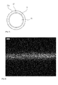
- an electrode wire for electro-discharge machining includes a brass core wire 21, which is finely formed with a diameter of 0.25mm and includes 65 weight% of copper and 35 weight% of zinc.
- the brass core wire 21, which has been finely formed includes a first alloy layer 22 having a size of about 1 ⁇ m to about 3 ⁇ m and a second alloy layer 23 having a size of about 2 ⁇ m to about 20 ⁇ m.
- a corrugation 23a is formed on the surface of the second alloy layer 23.
- the corrugation 23a may be formed by using an additional dice roller (not shown) for forming a wrinkle during a fine wire process for a plated core wire.
- the electrode wire for electro-discharge machining according to the present invention may be finely formed with a diameter of about 0.25mm and include the brass core wire 21 including 65 weight% of copper and 35 weight% of zinc.
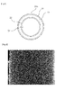
- the brass core wire 21, which has been finely formed includes the first alloy layer 22 having a size of about 1 ⁇ m to about 3 ⁇ m and the second alloy layer 23 having a size of about 2 ⁇ m to about 20 ⁇ m.
- the second alloy layer 23 is provided on the surface thereof with an oxidization layer 24 having a corrugation 24a.
- the corrugation 24a formed in the oxidization layer 24 may be obtained by properly controlling the condition of forming the oxidization layer 24.
- the electrode wire for electro-discharge machining of the present invention since the first alloy layer 22 and the second alloy layer 23 are formed on an outer layer of the core wire 21 through the mutual diffusion reaction between the core wire 21 and zinc metal as the core wire plated with zinc is subject to a heat treatment process for predetermined hours at the low temperature of 60°C to 490°C after the core wire with zinc has been finely formed, the interfacial surface or cracks are not formed, and the tensile strength of the electrode wire can be maintained in the range of about 400 N/mm 2 t01100N/mm 2 .
- the electrode wire for electro-discharge machining having the above structure is secondarily subject to a heat treatment step so that the mechanical property of the electrode wire can be more stabilized.
- FIG. 3 is a photograph showing the electrode wire for electro-discharge machining according to the present invention, the surface of which has no oxidization layer
- FIG. 5 is a photograph showing the electrode wire for electro-discharge machining according to the present invention, the surface of which has an oxidization layer.
- the core wire 21 may include various metals including copper or brass.
- the electrical conductivity and the mechanical strength required as an electrode wire are satisfied by the core wire 21.
- the second alloy layer 23 includes a material representing a melting point and a vaporization temperature lower than those of a material, such as zinc, constituting the core wire 12 to protect the core wire 12 and to improve the machining speed when the electro-discharge machining is performed.
- the material must represent a melting point and a vaporization temperature lower than those of the core wire 21, must be electroplated on the core wire including copper (Cu) or brass, and must allow an alloy layer to represent a lower vaporization temperature through a diffusion reaction in the heat treatment process after the electroplating process has been performed.
- the metal includes zinc (Zn), aluminum (Al), or tin (Sn).
- the corrugated surface is homogeneous without cracks, so that the fragments may be less crated from the core wire and the alloy layer in the electrode wire when performing electro-discharge machining, and the surface roughness of a workpiece may be increased.
- a method for manufacturing the electrode wire for the electro-discharge machining having the above structure according to the present invention and the operating effects thereof will be described in detail through Embodiments 1 and 2.
- the core wire is cleaned while passing through an alkaline degreasing bath. Then, after the core wire is subject to an acidic washing process, the core wire is cleaned again.
- a zinc-electroplating process is performed with respect to the washed core wire by using zinc serving as second metal and applying current of 770A at a line speed of 20m/min so that the core wire is plated at a predetermined thickness.
- the intermediate wire rod which has been subject to the zinc-electroplating process, is finely drawn so that the intermediate wire rod has a diameter of 0.25 mm.
- a corrugation having a predetermined pattern is formed on the surface of the intermediate wire rod by passing the intermediate wire rod through a dice (jig, not shown) for forming a wrinkle.
- the corrugation formed on the surface of the intermediate wire rod is formed by engraving the surface of the fine wire, which maintains the diameter of a finished product, in the shape of a wave.
- the intermediate wire rod which is finely formed and strengthened, and has the diameter of the finished product, is subject to the heat treatment process at a temperature of 60°C to 490°C for one hour to 120 hours.
- the first alloy layer 22 including copper-zinc is formed at the boundary surface between the core wire (first metal) and the second metal, which is zinc-electroplated, through the mutual diffusion reaction between the core wire and the second metal by the above heat treatment process, and the second alloy layer 23 including zinc-copper is formed at the outer portion of the first alloy layer 22.
- the shape of the corrugation 23a formed before the mutual thermal diffusion can be maintained.
- the shape of the boundary part to distinguish between the first and second alloy layers 22 and 23 may be varied according to the corrugation or the diffusion thickness of the alloy layer.
- the second alloy layer including zinc-copper represents the highest hardness and an elongation ratio lower than that of the core wire.
- the first alloy layer including copper-zinc is formed in the size of 1 ⁇ m to 3 ⁇ m at the boundary surface of the core wire and the second alloy plated layer including zinc-copper is formed in the size of 2 ⁇ m to 20 ⁇ m at an outer portion of the first alloy layer.
- the first alloy layer is formed due to the mutual diffusion reaction between the first metal constituting the core wire and zinc (i.e., the second metal) plated in the electroplating process, and the second alloy layer is formed by diffusing the components of the first metal constituting the core wire toward the second metal that is zinc-electroplated.
- the surface of the electrode wire corrugated in a predetermined pattern is not cracked as shown in FIG. 3 , but maintained with the tensile strength of 400 N/mm 2 to1100N/mm 2 .
- the mechanical property of the electrode wire can be stabilized by additionally performing the heat treatment process within 0.05 seconds to 3 seconds at the temperature of 300°C to 600°C .
- the workpieces are compared with each other in terms of the machining speed and the surface roughness in the case of forming a start hole at the center of a metallic board (SKD-11) having a thickness of 40 mm and performing electro-discharge machining for the workpieces to form a hexahedron having a length of 20 mm, a width of 10 mm, and a thickness of 40 mm.
- a metallic board SMD-11
- the front and rear sides of the workpiece described in table 1 refer to both sides of the workpiece at the region of 20 mm of the workpiece, and the primary to tertiary cuttings refer to the process for sequentially trimming a cut part of the workpiece three times after initially cutting the workpiece.
- the electrode wire for electro-discharge machining according to the first embodiment can significantly improve the surface roughness of the workpiece even though the machining speed of the workpiece is slightly increased when the electro-discharge machining is performed.
- the core wire is cleaned while passing through an alkaline degreasing bath. Then, after the core wire is subject to an acidic washing process, the core wire is cleaned again.
- a zinc-electroplating process is performed with respect to the washed core wire by using zinc serving as second metal and applying current of 770A at a line speed of 20m/min so that the core wire is plated at a predetermined thickness.
- the intermediate wire rod which has been subject to the zinc-electroplating process, is finely drawn so that the intermediate wire rod has a diameter of 0.25 mm.
- the intermediate wire rod which has been finely formed and strengthened, is subject to a heat treatment process for one hour to 120 hours at an oxidization atmosphere of 60°C to 490°C .
- the corrugation 24a having a predetermined pattern may be formed on the surface of the oxidization layer 24 in a longitudinal direction of the electrode wire by properly controlling the condition of forming the oxidization layer 24.
- the shape of the corrugation 24a is determined according to the conditions such as the temperature and the time of an oxygen atmosphere, and an amount of introduced oxygen in the process of forming the oxidation layer by diffusing and infiltrating oxygen into a predetermined depth of the zinc-electroplated layer.
- the first alloy layer 22 including copper-zinc is formed through the mutual diffusion reaction at the boundary surface between the core wire (first metal) and the second metal that is zinc-electroplated, the second alloy layer 23 including zinc-copper is formed at the outer portion of the first alloy layer 22, and the oxidization layer 24 having the corrugation 24a is formed at the outer portion of the first alloy layer 22.
- the second alloy layer including zinc-copper represents the highest hardness and an elongation ratio lower than that of the core wire.
- the first alloy layer including copper-zinc is formed in the size of 1 ⁇ m to 3 ⁇ m at the boundary surface of the core wire and the second alloy plated layer including zinc-copper is formed in the size of 2 ⁇ m to 20 ⁇ m at an outer portion of the first alloy layer.
- the first alloy layer is formed due to the mutual diffusion reaction between the first metal of the core wire and zinc (i.e., the second metal), which is a material plated in the electroplating process, and the second alloy layer is formed by mutually diffusing the first metallic component constituting the core wire toward the second metal that is zinc-electroplated.
- the oxidization layer 24 having the corrugation 24a is formed on the surface of the second alloy layer.
- the corrugation 24a formed by the oxidization layer 24 formed on the surface of the second alloy layer is engraved in the shape of a wave. Since the electrode wire fabricated as described above is subject to the heat treatment process after the fine wire process, cracks or an interfacial surface is created on the surface of the electrode wire as shown in Fig. 5 , but the tensile strength of the surface is maintained in the range of 400 N/mm 2 t01100N/mm 2 .
- the electrode wire for electro-discharge machining is additionally subject to a heat treatment step within 0.05 secs to 3 secs at the atmosphere having a temperature of 300°C to 600°C, so that the mechanical property of the electrode wire can be more stabilized.
- the workpieces are compared with each other in terms of the machining speed and the surface roughness in the case of forming a start hole at the center of a metallic board (SKD-11) having a thickness of 40 mm and performing electro-discharge machining for the workpieces to form a hexahedron having a length of 20 mm, a width of 10 mm, and a thickness of 40 mm.
- a metallic board SMD-11
- the front and rear sides of the workpiece described in table 2 refer to both sides of the workpiece at the range of 20 mm of the workpiece, and the primary to tertiary cuttings refer to processes of sequentially trimming a cut part of a workpiece three times after the workpiece has been initially cut.
- Table 2 classification embodiment 1 (sample 1) embodiment 1 (sample 2) conventional brass wire initial cutting time 19 mins 22 secs 19 mins 14 secs 20 mins 22 secs primary cutting time for trimming 12 mins 35 secs 12 mins 29 secs 12 mins 57 secs secondary cutting time for trimming 8 mins 42 secs 8 mins 27 secs 8 mins 29 secs tertiary cutting time for trimming 9 mins 33 secs 9 mins 26 secs 9 mins 42 secs total cutting time 50 mins 12 secs 49 mins 36 secs 51 mins 30 secs cutting time ratio 103% 104% 100% surface roughness (ra) front side 0279 0259 0395 surface roughness (ra) rear side 0247 0256 0374
- the electrode wire for electro-discharge machining according to the second embodiment can greatly improve the surface roughness of the workpiece even though the machining speed of the workpiece is significantly increased when the electro-discharge machining is performed.
- the surface of the electrode wire becomes smooth without cracks, and the surface areas of the electrode wire are increased due to the corrugation formed on the surface of the electrode wire. Accordingly, micro-fragments are less created, and the machining speed and the surface roughness of the workpiece can be improved.
- the first metal may include copper (Cu) or the alloy thereof in addition to brass
- the second metal may include silver (Ag), zinc (Zn), aluminum (Al), tin (Sn), or the alloy thereof.
Landscapes
- Chemical & Material Sciences (AREA)
- Engineering & Computer Science (AREA)
- Chemical Kinetics & Catalysis (AREA)
- Materials Engineering (AREA)
- Metallurgy (AREA)
- Organic Chemistry (AREA)
- Mechanical Engineering (AREA)
- Electrochemistry (AREA)
- Electrical Discharge Machining, Electrochemical Machining, And Combined Machining (AREA)
Applications Claiming Priority (1)
| Application Number | Priority Date | Filing Date | Title |
|---|---|---|---|
| KR1020110078517A KR101292343B1 (ko) | 2011-08-08 | 2011-08-08 | 방전가공용 전극선 및 그 제조방법 |
Publications (1)
| Publication Number | Publication Date |
|---|---|
| EP2556911A1 true EP2556911A1 (de) | 2013-02-13 |
Family
ID=46982371
Family Applications (1)
| Application Number | Title | Priority Date | Filing Date |
|---|---|---|---|
| EP12178039A Withdrawn EP2556911A1 (de) | 2011-08-08 | 2012-07-26 | Drahtelektrode zum Elektroerodieren und Herstellungsverfahren dafür |
Country Status (5)
| Country | Link |
|---|---|
| US (1) | US9156100B2 (de) |
| EP (1) | EP2556911A1 (de) |
| JP (1) | JP2013035119A (de) |
| KR (1) | KR101292343B1 (de) |
| CN (1) | CN102922065B (de) |
Cited By (3)
| Publication number | Priority date | Publication date | Assignee | Title |
|---|---|---|---|---|
| EP3154735A4 (de) * | 2014-06-10 | 2018-01-17 | Global Innovative Products, LLC | Piezoelektrische drahterodiermaschine |
| CN108856935A (zh) * | 2018-07-18 | 2018-11-23 | 宁波正锦和精密贸易有限公司 | 放电加工用电极丝及其制造方法 |
| EP3251777B1 (de) | 2015-12-02 | 2024-02-07 | Ningbo Kangqiang Micro-Electronics Technology Co., Ltd. | Plättchenartiges elektrodendrahtmaterial mit mikrostruktur und herstellungsverfahren dafür und verwendung davon |
Families Citing this family (13)
| Publication number | Priority date | Publication date | Assignee | Title |
|---|---|---|---|---|
| DE102013009767A1 (de) * | 2013-06-11 | 2014-12-11 | Heinrich Stamm Gmbh | Drahtelektrode zum funkenerosiven Schneiden von Gegenständen |
| CN103537768B (zh) * | 2013-11-12 | 2015-08-12 | 宁波博威麦特莱科技有限公司 | 慢走丝电火花放电加工用电极丝及其制备方法 |
| CN104999146A (zh) * | 2015-08-10 | 2015-10-28 | 江苏塞维斯数控科技有限公司 | 用于中走丝线切割机的刀具 |
| JP6238938B2 (ja) * | 2015-08-10 | 2017-11-29 | 元祥金屬工業股▲ふん▼有限公司 | 放電加工用電極線の製造方法 |
| CN107671379A (zh) * | 2017-09-26 | 2018-02-09 | 宁波康强微电子技术有限公司 | 织构化镀层电极丝的制备方法 |
| DE102018200308B4 (de) * | 2018-01-10 | 2019-07-25 | Fraunhofer-Gesellschaft zur Förderung der angewandten Forschung e.V. | Verfahren zur herstellung einer werkzeugelektrode und verfahren zu ihrer verwendung |
| CN108188516A (zh) * | 2018-01-16 | 2018-06-22 | 湖州华科信息咨询有限公司 | 一种使用电极丝进行慢走丝线切割加工的方法 |
| EP3924129A1 (de) * | 2019-05-10 | 2021-12-22 | Berkenhoff GmbH | Drahtelektrode zum funkenerosiven schneiden und verfahren zu deren herstellung |
| CN110125499B (zh) * | 2019-05-14 | 2020-12-08 | 宁波博德高科股份有限公司 | 表层含碳的慢走丝电火花加工用电极丝及其制备方法 |
| CN110093644B (zh) * | 2019-05-15 | 2021-04-16 | 江苏兴达钢帘线股份有限公司 | 一种钢丝、其制造方法、钢丝绳及输送带 |
| CN112222552B (zh) * | 2020-09-07 | 2022-08-26 | 宁波康强微电子技术有限公司 | 一种伽马电极丝及其制备方法 |
| TWI784706B (zh) * | 2021-09-10 | 2022-11-21 | 德商貝肯赫佛股份有限公司 | 用於電火花沖蝕切割的線狀電極 |
| CN116024424A (zh) * | 2022-12-30 | 2023-04-28 | 诺克威新材料(江苏)有限公司 | 一种减缓铜及铜合金极细线老化的方法 |
Citations (6)
| Publication number | Priority date | Publication date | Assignee | Title |
|---|---|---|---|---|
| GB2059324A (en) * | 1979-10-11 | 1981-04-23 | Charmilles Sa Ateliers | Electrode wire |
| JP2000141131A (ja) * | 1998-11-04 | 2000-05-23 | Oki Electric Cable Co Ltd | ワイヤ放電加工用電極線 |
| JP2001219318A (ja) * | 2000-02-08 | 2001-08-14 | Hitachi Cable Ltd | ワイヤ放電加工用電極線及びその製造方法 |
| JP2001334415A (ja) * | 2000-05-26 | 2001-12-04 | Oki Electric Cable Co Ltd | ワイヤカット放電加工用電極線 |
| JP2002126949A (ja) * | 2000-10-23 | 2002-05-08 | Sumitomo Metal Mining Co Ltd | ワイヤ放電加工用電極線 |
| KR100518733B1 (ko) | 1997-07-30 | 2005-10-05 | (주)징크젯 | 방전가공용 다공성 전극선의 제조방법 |
Family Cites Families (11)
| Publication number | Priority date | Publication date | Assignee | Title |
|---|---|---|---|---|
| GB2058324B (en) * | 1979-09-14 | 1983-11-02 | Hisaka Works Ltd | Surface condenser |
| JPS6143038A (ja) * | 1984-08-07 | 1986-03-01 | Toshiba Corp | シミユレ−シヨン機能付デ−タ中継装置 |
| JPH0332524A (ja) * | 1989-06-29 | 1991-02-13 | Hikari Tekkosho:Kk | 放電加工機に用いるワイヤー |
| RU1814580C (ru) * | 1991-06-17 | 1993-05-07 | Красноярский институт космической техники | Устройство дл пространственного гофрировани проволок |
| JPH06143038A (ja) * | 1992-10-29 | 1994-05-24 | Mitsubishi Electric Corp | 放電加工用ワイヤ電極 |
| JP2004188522A (ja) * | 2002-12-10 | 2004-07-08 | Hitachi Cable Ltd | ワイヤ放電加工用電極線の製造方法 |
| KR100484990B1 (ko) * | 2002-12-24 | 2005-04-22 | 주식회사 풍국통상 | 용융아연도금법을 이용한 방전가공기용 아연 코팅 전극선제조방법 |
| JP2006159304A (ja) * | 2004-12-02 | 2006-06-22 | Hongduk Steel Cord Co Ltd | ワイヤ放電加工用電極線及びその製造方法 |
| FR2881974B1 (fr) * | 2005-02-11 | 2007-07-27 | Thermocompact Sa | Fil composite pour electroerosion. |
| WO2009028117A1 (ja) * | 2007-12-10 | 2009-03-05 | Oki Electric Cable Co., Ltd. | ワイヤ放電加工用電極線、その製造方法及びその母線製造装置 |
| KR101284495B1 (ko) * | 2011-04-29 | 2013-07-16 | 성기철 | 방전가공용 전극선 및 그 제조방법 |
-
2011
- 2011-08-08 KR KR1020110078517A patent/KR101292343B1/ko active Active
-
2012
- 2012-07-26 EP EP12178039A patent/EP2556911A1/de not_active Withdrawn
- 2012-08-01 JP JP2012171036A patent/JP2013035119A/ja active Pending
- 2012-08-07 US US13/568,732 patent/US9156100B2/en not_active Expired - Fee Related
- 2012-08-08 CN CN201210280754.8A patent/CN102922065B/zh active Active
Patent Citations (8)
| Publication number | Priority date | Publication date | Assignee | Title |
|---|---|---|---|---|
| GB2059324A (en) * | 1979-10-11 | 1981-04-23 | Charmilles Sa Ateliers | Electrode wire |
| KR100518733B1 (ko) | 1997-07-30 | 2005-10-05 | (주)징크젯 | 방전가공용 다공성 전극선의 제조방법 |
| KR100518727B1 (ko) | 1997-07-30 | 2005-10-05 | (주)징크젯 | 방전가공용 다공성 전극선 |
| KR100518731B1 (ko) | 1997-07-30 | 2005-10-05 | (주)징크젯 | 방전가공용 다공성 전극선의 제조방법 |
| JP2000141131A (ja) * | 1998-11-04 | 2000-05-23 | Oki Electric Cable Co Ltd | ワイヤ放電加工用電極線 |
| JP2001219318A (ja) * | 2000-02-08 | 2001-08-14 | Hitachi Cable Ltd | ワイヤ放電加工用電極線及びその製造方法 |
| JP2001334415A (ja) * | 2000-05-26 | 2001-12-04 | Oki Electric Cable Co Ltd | ワイヤカット放電加工用電極線 |
| JP2002126949A (ja) * | 2000-10-23 | 2002-05-08 | Sumitomo Metal Mining Co Ltd | ワイヤ放電加工用電極線 |
Cited By (3)
| Publication number | Priority date | Publication date | Assignee | Title |
|---|---|---|---|---|
| EP3154735A4 (de) * | 2014-06-10 | 2018-01-17 | Global Innovative Products, LLC | Piezoelektrische drahterodiermaschine |
| EP3251777B1 (de) | 2015-12-02 | 2024-02-07 | Ningbo Kangqiang Micro-Electronics Technology Co., Ltd. | Plättchenartiges elektrodendrahtmaterial mit mikrostruktur und herstellungsverfahren dafür und verwendung davon |
| CN108856935A (zh) * | 2018-07-18 | 2018-11-23 | 宁波正锦和精密贸易有限公司 | 放电加工用电极丝及其制造方法 |
Also Published As
| Publication number | Publication date |
|---|---|
| CN102922065B (zh) | 2015-10-07 |
| KR20130016522A (ko) | 2013-02-18 |
| CN102922065A (zh) | 2013-02-13 |
| KR101292343B1 (ko) | 2013-07-31 |
| US20130037523A1 (en) | 2013-02-14 |
| JP2013035119A (ja) | 2013-02-21 |
| US9156100B2 (en) | 2015-10-13 |
Similar Documents
| Publication | Publication Date | Title |
|---|---|---|
| US9156100B2 (en) | Electrode wire for electro-discharge machining and method for manufacturing the same | |
| EP2517817B1 (de) | Elektrodendraht zum Funkenerodieren und Herstellungsverfahren dafür | |
| US6306523B1 (en) | Method of manufacturing porous electrode wire for electric discharge machining and structure of the electrode wire | |
| US7687738B2 (en) | Wire for high-speed electrical discharge machining | |
| JP2005512826A5 (de) | ||
| US20150360309A1 (en) | Electrode wire for wire electric discharge machining, and method for producing same | |
| EP2724805A1 (de) | Elektrodendraht zum Drahterodieren und Herstellungsverfahren dafür | |
| KR100528850B1 (ko) | 방전가공기용의 다기능 다층 코팅 전극선 및 그의 제조방법 | |
| JP2006159304A (ja) | ワイヤ放電加工用電極線及びその製造方法 | |
| KR20140100796A (ko) | 방전가공용 전극선 및 그 제조방법 | |
| KR100485645B1 (ko) | 와이어 방전가공용 전극선과 그 제조 방법 | |
| KR20130030797A (ko) | 방전가공용 전극선 및 그 제조방법 | |
| KR20140075442A (ko) | 방전가공용 전극선 및 그 제조방법 | |
| KR200350116Y1 (ko) | 방전가공기용의 다기능 다층 코팅 전극선 | |
| JP2004009207A (ja) | ワイヤ放電加工用電極線 |
Legal Events
| Date | Code | Title | Description |
|---|---|---|---|
| PUAI | Public reference made under article 153(3) epc to a published international application that has entered the european phase |
Free format text: ORIGINAL CODE: 0009012 |
|
| AK | Designated contracting states |
Kind code of ref document: A1 Designated state(s): AL AT BE BG CH CY CZ DE DK EE ES FI FR GB GR HR HU IE IS IT LI LT LU LV MC MK MT NL NO PL PT RO RS SE SI SK SM TR |
|
| AX | Request for extension of the european patent |
Extension state: BA ME |
|
| STAA | Information on the status of an ep patent application or granted ep patent |
Free format text: STATUS: THE APPLICATION IS DEEMED TO BE WITHDRAWN |
|
| 18D | Application deemed to be withdrawn |
Effective date: 20130814 |