EP2556939A1 - Dispositif de clapets avec un joint d'étanchéité surmoulé sur le clapet, procédé et demi-produit destinés à sa fabrication - Google Patents
Dispositif de clapets avec un joint d'étanchéité surmoulé sur le clapet, procédé et demi-produit destinés à sa fabrication Download PDFInfo
- Publication number
- EP2556939A1 EP2556939A1 EP11177437A EP11177437A EP2556939A1 EP 2556939 A1 EP2556939 A1 EP 2556939A1 EP 11177437 A EP11177437 A EP 11177437A EP 11177437 A EP11177437 A EP 11177437A EP 2556939 A1 EP2556939 A1 EP 2556939A1
- Authority
- EP
- European Patent Office
- Prior art keywords
- flap
- housing
- relative
- geometry
- flow channel
- Prior art date
- Legal status (The legal status is an assumption and is not a legal conclusion. Google has not performed a legal analysis and makes no representation as to the accuracy of the status listed.)
- Withdrawn
Links
Images

Classifications
-
- B—PERFORMING OPERATIONS; TRANSPORTING
- B29—WORKING OF PLASTICS; WORKING OF SUBSTANCES IN A PLASTIC STATE IN GENERAL
- B29C—SHAPING OR JOINING OF PLASTICS; SHAPING OF MATERIAL IN A PLASTIC STATE, NOT OTHERWISE PROVIDED FOR; AFTER-TREATMENT OF THE SHAPED PRODUCTS, e.g. REPAIRING
- B29C45/00—Injection moulding, i.e. forcing the required volume of moulding material through a nozzle into a closed mould; Apparatus therefor
- B29C45/0053—Injection moulding, i.e. forcing the required volume of moulding material through a nozzle into a closed mould; Apparatus therefor combined with a final operation, e.g. shaping
- B29C45/0055—Shaping
-
- B—PERFORMING OPERATIONS; TRANSPORTING
- B29—WORKING OF PLASTICS; WORKING OF SUBSTANCES IN A PLASTIC STATE IN GENERAL
- B29C—SHAPING OR JOINING OF PLASTICS; SHAPING OF MATERIAL IN A PLASTIC STATE, NOT OTHERWISE PROVIDED FOR; AFTER-TREATMENT OF THE SHAPED PRODUCTS, e.g. REPAIRING
- B29C45/00—Injection moulding, i.e. forcing the required volume of moulding material through a nozzle into a closed mould; Apparatus therefor
- B29C45/0017—Injection moulding, i.e. forcing the required volume of moulding material through a nozzle into a closed mould; Apparatus therefor moulding interconnected elements which are movable with respect to one another, e.g. chains or hinges
-
- B—PERFORMING OPERATIONS; TRANSPORTING
- B29—WORKING OF PLASTICS; WORKING OF SUBSTANCES IN A PLASTIC STATE IN GENERAL
- B29C—SHAPING OR JOINING OF PLASTICS; SHAPING OF MATERIAL IN A PLASTIC STATE, NOT OTHERWISE PROVIDED FOR; AFTER-TREATMENT OF THE SHAPED PRODUCTS, e.g. REPAIRING
- B29C45/00—Injection moulding, i.e. forcing the required volume of moulding material through a nozzle into a closed mould; Apparatus therefor
- B29C45/0081—Injection moulding, i.e. forcing the required volume of moulding material through a nozzle into a closed mould; Apparatus therefor of objects with parts connected by a thin section, e.g. hinge, tear line
-
- B—PERFORMING OPERATIONS; TRANSPORTING
- B29—WORKING OF PLASTICS; WORKING OF SUBSTANCES IN A PLASTIC STATE IN GENERAL
- B29C—SHAPING OR JOINING OF PLASTICS; SHAPING OF MATERIAL IN A PLASTIC STATE, NOT OTHERWISE PROVIDED FOR; AFTER-TREATMENT OF THE SHAPED PRODUCTS, e.g. REPAIRING
- B29C45/00—Injection moulding, i.e. forcing the required volume of moulding material through a nozzle into a closed mould; Apparatus therefor
- B29C45/14—Injection moulding, i.e. forcing the required volume of moulding material through a nozzle into a closed mould; Apparatus therefor incorporating preformed parts or layers, e.g. injection moulding around inserts or for coating articles
- B29C45/14754—Injection moulding, i.e. forcing the required volume of moulding material through a nozzle into a closed mould; Apparatus therefor incorporating preformed parts or layers, e.g. injection moulding around inserts or for coating articles being in movable or releasable engagement with the coating, e.g. bearing assemblies
-
- B—PERFORMING OPERATIONS; TRANSPORTING
- B29—WORKING OF PLASTICS; WORKING OF SUBSTANCES IN A PLASTIC STATE IN GENERAL
- B29L—INDEXING SCHEME ASSOCIATED WITH SUBCLASS B29C, RELATING TO PARTICULAR ARTICLES
- B29L2031/00—Other particular articles
- B29L2031/748—Machines or parts thereof not otherwise provided for
- B29L2031/7506—Valves
Definitions
- the present invention relates to a method for casting, in particular injection-molding production of a flap device, in particular throttle device, preferably for use in motor vehicles, wherein the flap device comprises a housing which surrounds a flow channel section, and further comprises a flap so movably received on the housing relative to this in that the effective flow cross-section of the flow channel section can be changed by relative displacement of the flap relative to the housing.
- the present invention further relates to a semi-finished product for producing the above-mentioned flap device and the flap device itself.
- the above-mentioned flap device which may have one or more flaps and typically one flap channel per flap, is preferably suitable for use in motor vehicles to provide gas flows there all types, such as a fresh gas supply to the internal combustion engine, flow rate by relative displacement of the at least one flap relative to the housing to change. It is also known, components of such a flap device, such as the flap on the one hand and the housing on the other hand, inexpensive injection molding manufacture.
- annular gap can form between an outer flap edge and a housing section surrounding this outer flap edge in the blocking position of the flap described above. Through this annular gap can continue to flow gas through the flow channel section, although actually a complete shut-off of the flow channel section is desired.
- this object is achieved by a method of the type mentioned, in which the housing and the valve already recorded flap are formed in a mold in a common casting step of a flowable casting molding shaping, namely with integral formation of a compared with the wall thicknesses of the housing and the flap thin G confusematerialphaseutens together with the flap and the housing, wherein the G confusematerialphaseutchen between an outer flap portion and the flap portion is provided in a blocking position of the flap relative to the housing housing portion, in which blocking position the flow cross-section of the flow channel portion in the rule is minimal.
- a semi-finished product is formed by the common casting step in a common mold, in which preferably at least the outer flap edge, but also any other suitable portion of the flap, with the housing section surrounding it in the blocking position of the flap by a comparison with the thickness dimension of the flap thin G cummaterialphaseutchen or a thin G manmaterialgrad is connected.
- the housing and flap are thus preferably produced in the casting step such that the flap is in the blocking position with respect to the housing, that is to say in a position in which the effective flow cross section of the flow channel section is generally minimal.
- This G tellmaterialnosutchen is thin compared to the material thickness of immediately adjacent to it flap portion, in particular flap edge, so that the G collectmaterialnosutchen can be cut with a tool, such as a blade, the flap with the same Tool can not be penetrated or only with disproportionately high power.
- the G hasslematerialkorchen may have about 1% to 40%, preferably 5% to 20%, more preferably 5% to 15%, the wall thickness or average wall thickness of the flap to ensure the above-described property.
- This G hasslestoffputchen integrally connecting the flap and the housing can be essentially the only difference between the demolded after the common casting step semi-finished and the finished, because functional, flap device.
- the method described here preferably comprises the step of severing the G stealmaterialphaseutchens.
- This cutting can, as already explained above, by a tool, in particular cutting tool occur.
- sufficiently thin G cummaterialphaseutchen also be thought to tear the G stealmaterialphaseutchen by forced relative movement of the flap and housing.
- the flap is provided on the finished flap device about a flap axis rotatable relative to the housing on this, if the method is a method step an insertion of a flap shaft component in the mold comprises.
- the flap shaft component can be, for example, a metal component or a component made of another material, which is more dimensionally stable than the cured casting material.
- the flap shaft member is not completely surrounded by casting material contributing to the formation of the flap, while in the case of overmolding the flap shaft component is completely surrounded by casting material contributing to the formation of the flap.
- a bearing means can be provided directly in the mold, which separates the material of the flap of the material of the housing after the casting process, that the flap is indeed received in the housing and supported on this, but in the area this holder casting material of the flap and casting material of the housing are separated by the bearing bush, so that it can come despite the geometric partial penetration of the housing through the flap to a relative movement of flap and housing.
- both the at least one bearing bush and the flap shaft component is inserted into the mold before the casting process, wherein it is advantageous if the method comprises the step of threading the flap shaft component in a bearing bush, preferably in all of the flap of the flap shaft component associated bearing bushes. Then namely the flap shaft component can enforce the bushing and provide not only between the bearing points of the flap on the housing, but especially in the bearing points of the flap on the housing for increased stability of the flap and thus the entire flap device.
- a semifinished product of a flap device in particular throttle device, preferably for use in motor vehicles
- the finished flap device comprises a housing which surrounds a flow channel section
- the finished flap device comprises a housing on the housing relative to this movably received flap, that is adjustable by a relative displacement of the flap relative to the housing, the effective flow cross-section of the flow channel section, in particular manufactured according to the method described above, wherein at least one Klappenabshnitt, in particular an outer flap edge , and a housing portion surrounding the flap in an operative state of the flap device, is connected via a thin material to be skinned compared with the wall thicknesses of the housing and the flap nd are thus integrally formed.
- Such a semi-finished product can be marketed as an independently tradable good on the market, for example from automotive suppliers, which deliver the semi-finished product with intact G stealmaterialphaseutchen to a motor vehicle manufacturer and this the date of commissioning of the semifinished product, ie the production of the flap device from the semifinished product by separation the G fauxmaterialphaseutchens, left.
- the flap on the finished flap device about a damper axis relative to the housing is rotatably provided on this, - may alternatively be thought of a translationally movable flap - it is advantageous if the flap a flap body and at least one with this for common movement having connected flap shaft portion.
- the flap body is then preferably that portion of the flap, with which the above-described change of the flow cross-section is effected by changing the relative arrangement and which is designed for this purpose.
- the flap shaft portion which is preferably integrally formed with the flap body for reasons of dimensional stability and dimensional stability and to avoid unwanted assembly work, is then adapted to receive the flap with the flap body rotatably mounted on the housing.
- the adjacent to the G confusematerialkorutchen flap edge is part of the valve body. In that case, it can then be ensured that the casting material pellet can in fact seal the undesired leakage gap described above.
- a particularly stable bearing of the flap relative rotation relative to the housing can be obtained in that the flap two with respect to the flap axis substantially collinear flap shaft sections wherein the flap body is provided axially between the flap shaft sections. Due to the arrangement of the valve body axially between the valve shaft sections also resulting from operational possibly occurring loads flap bend can be avoided or at least significantly reduced, which could otherwise affect the relative twistability of the flap relative to the housing.
- the flap device or the semifinished product made for the production thereof can have a plurality of flaps, for example if a plurality of identical flow channels lead to each cylinder of a multi-cylinder internal combustion engine and if the gas flow rate in each of the flow channels is to be variable.
- the flaps which are connected to one another at the finished flap relative to the housing relative to the housing, individually, d. H. separately from each other, produced and coupled together only after their production. Therefore, the individual of a plurality of flaps on the semifinished product can still be uncoupled, but can be coupled to one another by form fit geometries or can already be coupled to one another for joint movement.
- the housing may also consist of several housing parts, such as a housing part per flap.
- a housing part per flap it is also conceivable to combine several or even all of the flow channel sections substantially in a common housing part and to supplement this merely by further mounting parts in order to enable a relatively movable attachment of the flaps to the housing part.
- a structurally simple and the following assembly work considerably simplifying solution may be such that one of two connected to a valve body flap shaft portion, preferably at a free axial end thereof, has a coupling geometry and that the respective other flap shaft portion has a coupling counter-geometry, wherein the coupling geometry and the coupling counter-geometry can be positively coupled to a common rotational movement about the valve axis.
- each flap preferably has at one end a coupling geometry and at the other a coupling counter-geometry, so that only one type of flap needs to be manufactured and this flap can be axially lined up as often as required by coupling geometry and coupling counter-geometry so as to provide the desired number of flaps of the respective flap assembly reach.
- a safe and reliable torque transmission from a flap to each their axially adjacent which may be a prerequisite for joint movement, can be obtained in a simple manner that a geometry of coupling geometry and coupling counter-geometry a recess and the other geometry a torque transmitting in the recess insertable projection, preferably a complementary to at least a portion of the recess circumference projection has.
- the projection for torque transmission, the projection, as well as the recess, have a cross-sectional shape when viewing a valve axis orthogonal cross-section, which is bounded by a polygon.
- the projection can be formed prismatic be protrusion and recess for ease of installation can have insertion bevels. This means that the projection tapers with increasing axial distance from the valve body, while the recess tapers with increasing approach to the valve body.
- the preferred complementary configuration of recess and projection should not mean that in the coupled state of recess and projection no voids in the coupling structure more, because usually the recess must always be performed axially a little longer than the projection. Rather, it should be stated that the majority of the recess is taken after the coupling of material of the projection.
- a flap device in particular throttle device, preferably for use in motor vehicles, which comprises a housing which surrounds a flow channel portion, and further comprises a housing on the housing so relative to this movably received flap that a relative displacement of the flap relative to the housing of the effective flow cross section of the flow channel section is variable, in which flap device, a flap portion, preferably an outer flap edge, the at least one flap and / or a flap surrounding portion of the housing as a gap seal at maximum reduced by the flap flow cross-section between the flap portion, in particular flap edge of the flap, and the housing remaining gap has a, preferably completely, circumferential ridge of the same casting material, from which the flap portion, in particular flap edge of the flap, preferably the entire flap, and the housing portion are made.
- the flap device As described above, having a plurality of separately manufactured flaps, it is advantageous if the flap device comprises an actuating member, with which by an actuating device, such as an actuator, an actuating torque for relative rotation of flaps and housing in the Damper device can be introduced so that it can operate at a single actuation site, the entire flap device.
- an actuating device such as an actuator
- the actuation component can already be connected to the at least one flap of the flap device or can still be connected to it. Then it is to simplify the assembly work, but also to the usability of a substantially "universal" flap not only for coupling to another flap, but also for coupling to the operating member advantageous if the actuating member has a geometry of coupling geometry and coupling counter-geometry.
- the coupling ability of a plurality of individually produced flaps by the above-mentioned form-fit geometries should not exclude that these are additionally connected by material connection, such as by the low-distortion laser welding, or by gluing or otherwise operationally inextricably linked to an operation of the flap device with the most accurate change to ensure the flowing through the flow channel section gas flow.
- the above-described flap axis may be arranged such that it passes through the flap body substantially, that is, as in known butterfly flaps. It can also be thought that the flap axis is provided at a distance from the valve body, in which case the valve body is advantageously curved, so that the valve body in a passage position, in which the flow cross-section of the flow channel section is maximum, can rest against the wall of the housing or can cling to them at a short distance.
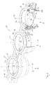
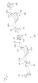
- a first embodiment of a flap device according to the invention is generally designated 10.
- the flap device 10 comprises three channel systems 12, 14 and 16, which are arranged side by side.
- the flap device 10 may have an over-housing 18, which is preferably designed as an integral component and in which further components of the flap device 10 may be accommodated.
- the flap device 10 comprises a housing 20 assigned to the channel system 12, a housing 22 assigned to the channel system 14, and a housing 24 assigned to the channel system 16.
- the flap device 10 has three flow channel sections 26, 28 and 30, in each channel system preferably one, so can be provided three housings 20, 22 and 24, which, as in the in Fig. 1 As shown, for example, the outer housing 18 in the illustrated example.
- the flap device 10 may include a seal assembly 31 around the flap assembly 10 in the direction of the flow channel sections 26, 28 and 30 to seal against a connector, not shown.
- the seal assembly 31 may serve to seal a gap that may exist between a housing 20, 22 or 24 and the housing 18.
- the flap device 10 may also have only one housing 20, two housings 20 and 22, or four or five or six or more housings with or without correspondingly configured housing or housing sections.
- the housing 20 with the flap 32 accommodated therein is described below, it being expressly pointed out that the flaps 34 and 36 are housed in the housings 22 and 22, respectively 24 may be identical, so that this description given for the housing 20 and its interior also applies to the housings 22 and 24.
- the above-mentioned sealing arrangement 31 is preferably a one-piece sealing element with housing seal portions 38, 40 and 42, which may be connected by webs 44 to form an integral component.
- seal assembly 31 preferably integrally connected, have end sealing loops 46 which can serve to seal end-side stub shaft recesses 48 on the housing 18 for receiving end-side stub shafts of the flaps 32, 34 and 36 to a connection piece.
- the seal assembly 31 is formed from a particularly suitable for sealing soft elastic material, for example by injection molding, in any case by a soft elastic material than the outer housing 18, which should show no or only the smallest possible deformation in the intended load case straight.
- the housing 20 and the flap 32 provided therein for relative rotation relative to the housing 20 about a valve axis K have been produced in a common molding tool in a common casting step from an identical casting material by casting, preferably by injection molding.
- a flap shaft component 50 which is formed of wear-resistant material than the flap 32 and the housing 20, threaded into bearing bushes 52 and inserted together with them in corresponding cavities and receptacles in the mold.
- the flap 32 which preferably has a flap body 32a and flap shaft sections 32b, is preferably mounted in the housing 20 with two bearing bushes 52 spaced apart in the axial direction with respect to the flap axis K. Axially between the bushings 52, the flap body 32a is preferably arranged so that operationally occurring forces, such as a gas flow along the flow channel section 26, no significant deflection of the flap 32 in the region of the channel axis K is to be feared, which the reliability of the flap device 10 considerably elevated.
- the flap shaft sections 32b which are preferably integrally formed on the flap body 32a, fill a region located radially inside the bushing 52 and contact the bearing bush 52 on a radially inner surface which is in support of the Drehlagerung the flap 32 is preferably cylindrical.
- the inner surface of the bushing 52 may additionally have undercut geometries, such as circumferential projections about the channel axis K and the like, to improve the support of the bearing bush 52 at the flap shaft portion 32 b.
- the housing 20 is at the receiving bushes 52 receiving points preferably radially outwardly encapsulated around the bushings 52, so that the housing 20 is materially separated by the bushes 52 of the flap 32, in particular of the flap shaft portions 32b, so that at the bearing a Relative mobility between the flap 32 and housing 20 is possible.
- Fig. 2 is the storage situation in the partial section well on the channel system 16 recognizable.
- the housing 24, as well as the other housing 20 and / or 22 of the flap device 10, may have a bearing extension 24a, which may rest on a radially outer surface 52a of the bearing bush 52 after removal of the flap device 10.
- the radially outer surface 52a of the bushing 52 may have an undercut geometry to improve the retention of the bushing 52 on the housing.
- the individual housings 20, 22 and 24 are inserted into corresponding staging spaces of the housing 18.
- the seal assembly 31 seals an annular gap between the housings 20, 22 and 24 and the housing 18.
- An anchoring profile 31 b may be formed on the sealing arrangement 31 at the end face opposite its sealing surface 31 a in order to ensure anchoring of the seal 31 to the housings 22, 22 or 24 and / or on the housing 18.
- the coupling shaft component 50 is preferably designed as a prism, for example as a cuboid, in order to facilitate the introduction or / and transmission of a torque acting around the valve axis K.
- the in Fig. 1 identifiable end portions 50a and 50b as positive locking geometries for coupling for example, in the Fig. 1 to 3c Serving components not shown serve, with which a the flaps 32, 34 and 36 actuated actuator for adjusting the flaps 32, 34 and 36 can act on this.
- the flap 32 in particular the flap body 32a of the flap device 10 illustrated in the presently discussed example, can be mirror-symmetrical to a plane of symmetry containing the flap axis K and in particular can extend along a plane.
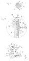
- annular gap 54 between the flap body 32a and the associated housing 20 to recognize, which exists even if the flap 32 in its in Fig. 3a shown blocking position is located.
- the annular gap 54 extends more exactly along the circumference of the flap body 32a between the flap shaft portions 32b, respectively.
- the G hasslematerialkorutchen 60 is generated in the common casting step, in which both the flap 32 and the housing 20 is formed.
- Fig. 3b thus shows a semifinished state of the flap device 10.
- FIG. 3b IIIc which contains the annular gap 54, is in FIG Fig. 3c shown enlarged.
- the material 60 has a substantially lower material thickness, for example a material thickness of 1 to 20% of the material thickness or middle material thickness of the flap body 32a.
- the G tellmaterialphaseutchen 60 Prior to start-up of the valve device 10, the G tellmaterialphaseutchen 60 is severed with a suitable tool, such as a blade. This can be done on the valve body 32a, then the G stealmaterialphaseutchen 60 remains as a ridge on the housing 20, or can be done on the housing 20, then the G collectmaterialphaseutchen 60 remains as a ridge on the valve body 32a. The latter is preferred due to the thus occurring flow conditions in the associated flow channel section.
- the G mandiotchen 60 After transection, the G mandiol 60 forms as a ridge or
- the G hasslematerialphasechen 60 is produced during common casting, in particular injection molding of flap 32 and housing 20 without significant costs by manufacturing costs and assembly costs and provides below a very effective annular gap seal ready.
- a second embodiment of the present invention is shown.
- the same components and component portions are provided with the same reference numerals as in the first embodiment of Fig. 1 to 3c , but increased by the number 100.
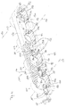
- the channel device 110 shown here has four substantially parallel flow channel sections 126, 128, 130 and 133, which are formed in a common housing 120.
- the housing 120 may be subdivided in such a way that one or more subgroups of flow channel sections are formed in a housing part. It can also be thought to form a separate housing for each flow channel section.
- the housing 120 may be designed in several parts to facilitate the assembly of the embodiment of a flap device 110 shown here.
- the flaps 132, 134, 136 and 137 may be formed with flap bodies 132a, 134a, 136a and 137a curved according to the shape of the associated flow channel portion, which are then preferably spaced from the flap axis K, around which the entire flap assembly 139 relative to Housing 120 can be rotated. In the in Fig. 4 shown passage position are the valve body 132a, 134a, 136a, and 137a then preferably closely attaches to housing 120 to form a thin gap 141.
- valve bodies can then be in the in Fig. 4 shown passage position in which the respective flow channel sections in the housing 120 substantially have a maximum flow cross-section, create a conforming to the respective wall sections of the housing 120.
- the flap arrangement 139 preferably no flap component protrudes into the flow channel section assigned to it.
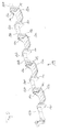
- the flap 137 comprises the already mentioned flap body 137a, from which project to both, with respect to the flap axis K, axial sides flap shaft portions 137b.
- the flap shaft portions 137b are integrally formed with the flap body 137a via land portions 137c.
- Both longitudinal ends of the flap shaft sections 137b which are remote from the flap body 137a can have form fit geometries, which can serve for the torque-transmitting connection with the respectively adjacent flap, here for example flap 136, or / and with an actuating component 162.
- both positive locking geometries can be formed as projections 164.
- the flaps 137 and 134 may be formed substantially identically, and the flaps 136 and 132 may be formed substantially identically, with the difference between adjacent flaps 137 and 136 (see FIGS Fig. 6 ) may consist in that the flap 136 instead of projections 164 coupling recesses 166 has.
- the flap 136 has recesses 166 at both longitudinal ends of the flap shaft sections 136b, remote from the flap body 136a, into which the projections 164 of adjacent flaps can be inserted to connect the flaps to transmit torque.
- each flap has a projection 164 at one longitudinal end of a flap shaft section and a corresponding recess 166 at the respective other longitudinal end. If then, based on the position to the valve body, always the same flap shaft sections have a projection and the other have a recess, it is sufficient to produce a kind of flaps. Essentially identical flaps can thus be put together to form a flap arrangement 139.
- the torque-transmitting components may be non-detachably connected by gluing, welding, or any other suitable method when used as intended.
- a laser welding method is recommended here, which minimizes the thermal distortion occurring and thus ensures the highest possible dimensional stability, combined with a smooth relative rotatability of the flap arrangement 139 relative to the housing 120.
- the coupling projections 164 are preferably constructed prismatic, so that they can transmit torque when combined with the corresponding coupling recesses 166 on the sides of their lateral surfaces.
- the coupling projections 164 are designed as a cuboid.
- flap projections 164 and flap recesses 166 are essentially complementary in the mounted state, that is to say they are complementary to one another, although this is not intended to mean that the coupling recess 166 is in one with a coupling projection 166 United state is completely filled by the coupling projection 164.
- the coupling recess 166 is formed axially longer than the coupling projection 164 already for manufacturing reasons.
- the coupling projection 164 and coupling recess 166 have at least one axial section in which almost the entire circumference of a coupling projection 164 rests on the circumference of the coupling recess 166. In this way, the flaps can be made individually and mounted with little effort to a flap assembly 139 of any length.
- the flap assembly 139 which in the Fig. 4 and 5 four flaps and an operating member 162 may, in alternative embodiments, comprise only one flap 137 and one operating member 162, or may, as in FIG Fig. 6 shown, only two flaps 137 and 136 and an actuating member 162 or may have only three, five, six or more flaps, each with or without operating member 162nd
- the actuating component also has a corresponding form-fit geometry, in this case a coupling recess 166.
- each flap shaft portion is surrounded by a housing extension member 121 and 123, respectively.
- the housing supplemental components 121 and 123 may be substantially identical and differ only in terms of their direction of curvature.
- the housing supplemental components 121 and 123 may be mirror-inverted with respect to a game mirror symmetry plane orthogonal to the channel axis K.
- the flaps required to form a flap arrangement 139 can be combined with one another via the form-fit geometries described above, and preferably fixed in a non-detachable manner.
- an actuating member 162 which can be connected to the flap assembly 139 to transmit torque end.
- the thus formed flap assembly 139 in the housing base member 125 which in Fig. 4 is shown, being used then the respective housing supplement components 121 and 123 complement the housing base member 125 to a housing with complete flow channel sections.
- a bearing bushing 152 can be provided between the housing extension components 121 or 123 and the flap shaft sections 137b, 136b, 134b, 132b passing through them.
- the flaps for example the flap 137
- the flaps may have been cast in a common casting step with the housing supplemental components 121 and 123 in a common mold, for example by injection molding.
- a set of bearing bushes 152 which after demolding the housing extension members 121 and 123 geometrically separated from the flap shaft portions 137b, etc., placed at corresponding locations in the mold and cast around casting material, in particular encapsulated.
- the supplemental components abut an outer surface 152a of the bushing 152, while the flap shaft portions 137b engage an inner surface 152b (see FIG Fig. 6 ) of the bushings 152 abut.
- a flap with the associated housing storage can be produced in a single casting step with high accuracy and substantially constant low bearing clearance without much effort.
- the casting material skin 160 cast in the casting process between the housing extension components 121 and 123 and the associated flap body is only connected to the respective flap body.
Landscapes
- Engineering & Computer Science (AREA)
- Manufacturing & Machinery (AREA)
- Mechanical Engineering (AREA)
- Lift Valve (AREA)
- Control Of Throttle Valves Provided In The Intake System Or In The Exhaust System (AREA)
Priority Applications (3)
| Application Number | Priority Date | Filing Date | Title |
|---|---|---|---|
| EP11177437A EP2556939A1 (fr) | 2011-08-12 | 2011-08-12 | Dispositif de clapets avec un joint d'étanchéité surmoulé sur le clapet, procédé et demi-produit destinés à sa fabrication |
| CN2012102831265A CN102922652A (zh) | 2011-08-12 | 2012-08-09 | 节气门装置及其制造方法,及制造该节气门装置的半成品 |
| US13/572,923 US20130037734A1 (en) | 2011-08-12 | 2012-08-13 | Valve device with gap seal injection-moulded onto valve, method and semi-finished product for the production thereof |
Applications Claiming Priority (1)
| Application Number | Priority Date | Filing Date | Title |
|---|---|---|---|
| EP11177437A EP2556939A1 (fr) | 2011-08-12 | 2011-08-12 | Dispositif de clapets avec un joint d'étanchéité surmoulé sur le clapet, procédé et demi-produit destinés à sa fabrication |
Publications (1)
| Publication Number | Publication Date |
|---|---|
| EP2556939A1 true EP2556939A1 (fr) | 2013-02-13 |
Family
ID=44582391
Family Applications (1)
| Application Number | Title | Priority Date | Filing Date |
|---|---|---|---|
| EP11177437A Withdrawn EP2556939A1 (fr) | 2011-08-12 | 2011-08-12 | Dispositif de clapets avec un joint d'étanchéité surmoulé sur le clapet, procédé et demi-produit destinés à sa fabrication |
Country Status (3)
| Country | Link |
|---|---|
| US (1) | US20130037734A1 (fr) |
| EP (1) | EP2556939A1 (fr) |
| CN (1) | CN102922652A (fr) |
Cited By (4)
| Publication number | Priority date | Publication date | Assignee | Title |
|---|---|---|---|---|
| DE102013006196A1 (de) * | 2013-04-11 | 2014-10-16 | Mann + Hummel Gmbh | Saugrohr für Gas einer Brennkraftmaschine mit einer Klappeneinheit |
| DE102015219724A1 (de) * | 2015-10-12 | 2017-04-13 | Mahle International Gmbh | Drosselklappenverstelleinrichtung |
| DE102016201078A1 (de) * | 2016-01-26 | 2017-07-27 | Mahle International Gmbh | Frischluftanlage für eine Brennkraftmaschine eines Kraftfahrzeugs |
| WO2022221769A1 (fr) * | 2021-04-16 | 2022-10-20 | Zephyros, Inc. | Renfort structural flexible |
Families Citing this family (2)
| Publication number | Priority date | Publication date | Assignee | Title |
|---|---|---|---|---|
| GB2534954B (en) * | 2015-07-21 | 2018-10-17 | Ford Global Tech Llc | Automated treatment process and apparatus |
| US10215105B1 (en) * | 2017-10-12 | 2019-02-26 | Continental Automotive Systems, Inc. | Integrated VDA housing with anti-rotation feature |
Citations (3)
| Publication number | Priority date | Publication date | Assignee | Title |
|---|---|---|---|---|
| US5794591A (en) * | 1997-03-17 | 1998-08-18 | Ford Motor Company | Throttle valve for an internal combustion engine |
| JP2000210983A (ja) * | 1999-01-21 | 2000-08-02 | Ge Plastics Japan Ltd | 空気流量制御装置およびその成形方法ならびにその成形型 |
| US20040163703A1 (en) * | 2001-08-31 | 2004-08-26 | Siemens Ag | Process for producing a throttle-valve housing and a throttle valve |
Family Cites Families (4)
| Publication number | Priority date | Publication date | Assignee | Title |
|---|---|---|---|---|
| ES2075189T3 (es) * | 1990-10-24 | 1995-10-01 | Volvo Ab | Valvula reguladora. |
| DE19918777A1 (de) * | 1999-04-24 | 2000-10-26 | Mann & Hummel Filter | Schaltklappenverband aus montagegespritzten Schaltklappen oder Klappenmodulen |
| DE10226594A1 (de) * | 2002-06-14 | 2004-01-08 | Robert Bosch Gmbh | Regelklappe mit eingespritzter Welle |
| JP4211574B2 (ja) * | 2003-11-07 | 2009-01-21 | 株式会社デンソー | 内燃機関用スロットル装置の成形方法 |
-
2011
- 2011-08-12 EP EP11177437A patent/EP2556939A1/fr not_active Withdrawn
-
2012
- 2012-08-09 CN CN2012102831265A patent/CN102922652A/zh active Pending
- 2012-08-13 US US13/572,923 patent/US20130037734A1/en not_active Abandoned
Patent Citations (3)
| Publication number | Priority date | Publication date | Assignee | Title |
|---|---|---|---|---|
| US5794591A (en) * | 1997-03-17 | 1998-08-18 | Ford Motor Company | Throttle valve for an internal combustion engine |
| JP2000210983A (ja) * | 1999-01-21 | 2000-08-02 | Ge Plastics Japan Ltd | 空気流量制御装置およびその成形方法ならびにその成形型 |
| US20040163703A1 (en) * | 2001-08-31 | 2004-08-26 | Siemens Ag | Process for producing a throttle-valve housing and a throttle valve |
Cited By (5)
| Publication number | Priority date | Publication date | Assignee | Title |
|---|---|---|---|---|
| DE102013006196A1 (de) * | 2013-04-11 | 2014-10-16 | Mann + Hummel Gmbh | Saugrohr für Gas einer Brennkraftmaschine mit einer Klappeneinheit |
| DE102013006196B4 (de) * | 2013-04-11 | 2016-07-07 | Mann + Hummel Gmbh | Saugrohr für Gas einer Brennkraftmaschine mit einer Klappeneinheit |
| DE102015219724A1 (de) * | 2015-10-12 | 2017-04-13 | Mahle International Gmbh | Drosselklappenverstelleinrichtung |
| DE102016201078A1 (de) * | 2016-01-26 | 2017-07-27 | Mahle International Gmbh | Frischluftanlage für eine Brennkraftmaschine eines Kraftfahrzeugs |
| WO2022221769A1 (fr) * | 2021-04-16 | 2022-10-20 | Zephyros, Inc. | Renfort structural flexible |
Also Published As
| Publication number | Publication date |
|---|---|
| CN102922652A (zh) | 2013-02-13 |
| US20130037734A1 (en) | 2013-02-14 |
Similar Documents
| Publication | Publication Date | Title |
|---|---|---|
| EP2622244B1 (fr) | Agencement de roue dentée et procédé de fabrication d'un emboîtement à baïonnette | |
| EP2556939A1 (fr) | Dispositif de clapets avec un joint d'étanchéité surmoulé sur le clapet, procédé et demi-produit destinés à sa fabrication | |
| EP3459706B1 (fr) | Roue cylindrique destinée à être utilisée dans un engrenage cylindrique, engrenage pour un engrenage cylindrique, engrenage cylindrique doté d'un tel engrenage ainsi que procédé de fabrication d'une roue cylindrique | |
| WO2013083526A1 (fr) | Assemblage entre deux éléments et procédé d'assemblage de deux éléments | |
| DE102021111839A1 (de) | Vorrichtung zur Handhabung von Fluid eines zumindest teilweise elektrisch angetriebenen Fahrzeugs | |
| DE102011006855A1 (de) | Schieberventil mit einem Gehäuse und einem in dem Gehäuse geführten Schieber | |
| EP2557298B1 (fr) | Dispositif à clapets doté d'au moins deux clapets spécialement fabriqués et montés ensemble pour un mouvement simultané | |
| DE102018208747A1 (de) | Montage-Spritzgussverfahren zur Herstellung einer Kfz-Luftklappenvorrichtung | |
| EP1420938B1 (fr) | Procede de fabrication d'un boitier tubulaire de clapet d'etranglement et d'un clapet d'etranglement | |
| EP1270904B1 (fr) | Procédé de fabrication d'un ensemble de volets de commande | |
| DE102004061057A1 (de) | Kugelgelenkverbindung zwischen einem Zapfen und einem Befestigungsteil | |
| DE102017109003A1 (de) | Zweidruckventil | |
| WO2008052782A1 (fr) | Soupape de non-retour | |
| EP3888870B1 (fr) | Procédé de fabrication d'une partie charnière d'une charnière de lunettes | |
| EP1826375B1 (fr) | Soupape de commutation et son procédé de fabrication | |
| DE102015222843A1 (de) | Klappenvorrichtung | |
| DE102008024200B4 (de) | Schaltwelle | |
| DE102013006196B4 (de) | Saugrohr für Gas einer Brennkraftmaschine mit einer Klappeneinheit | |
| EP2756198B1 (fr) | Butée de fin de course de rétraction pour la tige de piston d'un maître cylindre | |
| DE102005041874A1 (de) | Verfahren zur Herstellung einer Drosselklappeneinheit aus mehreren Kunststoffkomponenten | |
| DE202019106047U1 (de) | Doppelschneckenextruder mit Sicherheitskupplung | |
| EP2064047B1 (fr) | Procede et outil d'injection pour la fabrication d' un conduit d'admission en matiere synthetique pour moteurs a combustion interne et conduit d'admission ainsi fabrique | |
| DE102012223608A1 (de) | Ventileinsatzelement sowie Verfahren zur Ausbildung einer Nut an einem Gehäuse eines Ventileinsatzelements | |
| EP1394391A2 (fr) | Elément de soupape et ensemble de soupape | |
| DE102023133789A1 (de) | Auslaufstoppventil, insbesondere für eine Steckverbindung |
Legal Events
| Date | Code | Title | Description |
|---|---|---|---|
| PUAI | Public reference made under article 153(3) epc to a published international application that has entered the european phase |
Free format text: ORIGINAL CODE: 0009012 |
|
| AK | Designated contracting states |
Kind code of ref document: A1 Designated state(s): AL AT BE BG CH CY CZ DE DK EE ES FI FR GB GR HR HU IE IS IT LI LT LU LV MC MK MT NL NO PL PT RO RS SE SI SK SM TR |
|
| AX | Request for extension of the european patent |
Extension state: BA ME |
|
| 17P | Request for examination filed |
Effective date: 20130308 |
|
| STAA | Information on the status of an ep patent application or granted ep patent |
Free format text: STATUS: THE APPLICATION HAS BEEN WITHDRAWN |
|
| 18W | Application withdrawn |
Effective date: 20130422 |