EP2557009A2 - Système de gestion de l'énergie électrique d'un véhicule électrique hybride parallèle et procédé adaptatif de gestion de l'énergie électrique et programme associé - Google Patents
Système de gestion de l'énergie électrique d'un véhicule électrique hybride parallèle et procédé adaptatif de gestion de l'énergie électrique et programme associé Download PDFInfo
- Publication number
- EP2557009A2 EP2557009A2 EP12179640A EP12179640A EP2557009A2 EP 2557009 A2 EP2557009 A2 EP 2557009A2 EP 12179640 A EP12179640 A EP 12179640A EP 12179640 A EP12179640 A EP 12179640A EP 2557009 A2 EP2557009 A2 EP 2557009A2
- Authority
- EP
- European Patent Office
- Prior art keywords
- torque
- motor
- charge
- state
- electric vehicle
- Prior art date
- Legal status (The legal status is an assumption and is not a legal conclusion. Google has not performed a legal analysis and makes no representation as to the accuracy of the status listed.)
- Withdrawn
Links
Images


Classifications
-
- B—PERFORMING OPERATIONS; TRANSPORTING
- B60—VEHICLES IN GENERAL
- B60W—CONJOINT CONTROL OF VEHICLE SUB-UNITS OF DIFFERENT TYPE OR DIFFERENT FUNCTION; CONTROL SYSTEMS SPECIALLY ADAPTED FOR HYBRID VEHICLES; ROAD VEHICLE DRIVE CONTROL SYSTEMS FOR PURPOSES NOT RELATED TO THE CONTROL OF A PARTICULAR SUB-UNIT
- B60W20/00—Control systems specially adapted for hybrid vehicles
- B60W20/10—Controlling the power contribution of each of the prime movers to meet required power demand
- B60W20/11—Controlling the power contribution of each of the prime movers to meet required power demand using model predictive control [MPC] strategies, i.e. control methods based on models predicting performance
-
- B—PERFORMING OPERATIONS; TRANSPORTING
- B60—VEHICLES IN GENERAL
- B60K—ARRANGEMENT OR MOUNTING OF PROPULSION UNITS OR OF TRANSMISSIONS IN VEHICLES; ARRANGEMENT OR MOUNTING OF PLURAL DIVERSE PRIME-MOVERS IN VEHICLES; AUXILIARY DRIVES FOR VEHICLES; INSTRUMENTATION OR DASHBOARDS FOR VEHICLES; ARRANGEMENTS IN CONNECTION WITH COOLING, AIR INTAKE, GAS EXHAUST OR FUEL SUPPLY OF PROPULSION UNITS IN VEHICLES
- B60K6/00—Arrangement or mounting of plural diverse prime-movers for mutual or common propulsion, e.g. hybrid propulsion systems comprising electric motors and internal combustion engines
- B60K6/20—Arrangement or mounting of plural diverse prime-movers for mutual or common propulsion, e.g. hybrid propulsion systems comprising electric motors and internal combustion engines the prime-movers consisting of electric motors and internal combustion engines, e.g. HEVs
- B60K6/42—Arrangement or mounting of plural diverse prime-movers for mutual or common propulsion, e.g. hybrid propulsion systems comprising electric motors and internal combustion engines the prime-movers consisting of electric motors and internal combustion engines, e.g. HEVs characterised by the architecture of the hybrid electric vehicle
- B60K6/48—Parallel type
-
- B—PERFORMING OPERATIONS; TRANSPORTING
- B60—VEHICLES IN GENERAL
- B60W—CONJOINT CONTROL OF VEHICLE SUB-UNITS OF DIFFERENT TYPE OR DIFFERENT FUNCTION; CONTROL SYSTEMS SPECIALLY ADAPTED FOR HYBRID VEHICLES; ROAD VEHICLE DRIVE CONTROL SYSTEMS FOR PURPOSES NOT RELATED TO THE CONTROL OF A PARTICULAR SUB-UNIT
- B60W10/00—Conjoint control of vehicle sub-units of different type or different function
- B60W10/04—Conjoint control of vehicle sub-units of different type or different function including control of propulsion units
- B60W10/06—Conjoint control of vehicle sub-units of different type or different function including control of propulsion units including control of combustion engines
-
- B—PERFORMING OPERATIONS; TRANSPORTING
- B60—VEHICLES IN GENERAL
- B60W—CONJOINT CONTROL OF VEHICLE SUB-UNITS OF DIFFERENT TYPE OR DIFFERENT FUNCTION; CONTROL SYSTEMS SPECIALLY ADAPTED FOR HYBRID VEHICLES; ROAD VEHICLE DRIVE CONTROL SYSTEMS FOR PURPOSES NOT RELATED TO THE CONTROL OF A PARTICULAR SUB-UNIT
- B60W10/00—Conjoint control of vehicle sub-units of different type or different function
- B60W10/04—Conjoint control of vehicle sub-units of different type or different function including control of propulsion units
- B60W10/08—Conjoint control of vehicle sub-units of different type or different function including control of propulsion units including control of electric propulsion units, e.g. motors or generators
-
- B—PERFORMING OPERATIONS; TRANSPORTING
- B60—VEHICLES IN GENERAL
- B60W—CONJOINT CONTROL OF VEHICLE SUB-UNITS OF DIFFERENT TYPE OR DIFFERENT FUNCTION; CONTROL SYSTEMS SPECIALLY ADAPTED FOR HYBRID VEHICLES; ROAD VEHICLE DRIVE CONTROL SYSTEMS FOR PURPOSES NOT RELATED TO THE CONTROL OF A PARTICULAR SUB-UNIT
- B60W10/00—Conjoint control of vehicle sub-units of different type or different function
- B60W10/24—Conjoint control of vehicle sub-units of different type or different function including control of energy storage means
- B60W10/26—Conjoint control of vehicle sub-units of different type or different function including control of energy storage means for electrical energy, e.g. batteries or capacitors
-
- B—PERFORMING OPERATIONS; TRANSPORTING
- B60—VEHICLES IN GENERAL
- B60W—CONJOINT CONTROL OF VEHICLE SUB-UNITS OF DIFFERENT TYPE OR DIFFERENT FUNCTION; CONTROL SYSTEMS SPECIALLY ADAPTED FOR HYBRID VEHICLES; ROAD VEHICLE DRIVE CONTROL SYSTEMS FOR PURPOSES NOT RELATED TO THE CONTROL OF A PARTICULAR SUB-UNIT
- B60W20/00—Control systems specially adapted for hybrid vehicles
-
- B—PERFORMING OPERATIONS; TRANSPORTING
- B60—VEHICLES IN GENERAL
- B60W—CONJOINT CONTROL OF VEHICLE SUB-UNITS OF DIFFERENT TYPE OR DIFFERENT FUNCTION; CONTROL SYSTEMS SPECIALLY ADAPTED FOR HYBRID VEHICLES; ROAD VEHICLE DRIVE CONTROL SYSTEMS FOR PURPOSES NOT RELATED TO THE CONTROL OF A PARTICULAR SUB-UNIT
- B60W20/00—Control systems specially adapted for hybrid vehicles
- B60W20/10—Controlling the power contribution of each of the prime movers to meet required power demand
- B60W20/13—Controlling the power contribution of each of the prime movers to meet required power demand in order to stay within battery power input or output limits; in order to prevent overcharging or battery depletion
-
- B—PERFORMING OPERATIONS; TRANSPORTING
- B60—VEHICLES IN GENERAL
- B60W—CONJOINT CONTROL OF VEHICLE SUB-UNITS OF DIFFERENT TYPE OR DIFFERENT FUNCTION; CONTROL SYSTEMS SPECIALLY ADAPTED FOR HYBRID VEHICLES; ROAD VEHICLE DRIVE CONTROL SYSTEMS FOR PURPOSES NOT RELATED TO THE CONTROL OF A PARTICULAR SUB-UNIT
- B60W20/00—Control systems specially adapted for hybrid vehicles
- B60W20/10—Controlling the power contribution of each of the prime movers to meet required power demand
- B60W20/13—Controlling the power contribution of each of the prime movers to meet required power demand in order to stay within battery power input or output limits; in order to prevent overcharging or battery depletion
- B60W20/14—Controlling the power contribution of each of the prime movers to meet required power demand in order to stay within battery power input or output limits; in order to prevent overcharging or battery depletion in conjunction with braking regeneration
-
- B—PERFORMING OPERATIONS; TRANSPORTING
- B60—VEHICLES IN GENERAL
- B60W—CONJOINT CONTROL OF VEHICLE SUB-UNITS OF DIFFERENT TYPE OR DIFFERENT FUNCTION; CONTROL SYSTEMS SPECIALLY ADAPTED FOR HYBRID VEHICLES; ROAD VEHICLE DRIVE CONTROL SYSTEMS FOR PURPOSES NOT RELATED TO THE CONTROL OF A PARTICULAR SUB-UNIT
- B60W30/00—Purposes of road vehicle drive control systems not related to the control of a particular sub-unit, e.g. of systems using conjoint control of vehicle sub-units
- B60W30/18—Propelling the vehicle
- B60W30/18009—Propelling the vehicle related to particular drive situations
- B60W30/18109—Braking
- B60W30/18127—Regenerative braking
-
- B—PERFORMING OPERATIONS; TRANSPORTING
- B60—VEHICLES IN GENERAL
- B60W—CONJOINT CONTROL OF VEHICLE SUB-UNITS OF DIFFERENT TYPE OR DIFFERENT FUNCTION; CONTROL SYSTEMS SPECIALLY ADAPTED FOR HYBRID VEHICLES; ROAD VEHICLE DRIVE CONTROL SYSTEMS FOR PURPOSES NOT RELATED TO THE CONTROL OF A PARTICULAR SUB-UNIT
- B60W2510/00—Input parameters relating to a particular sub-units
- B60W2510/24—Energy storage means
- B60W2510/242—Energy storage means for electrical energy
- B60W2510/244—Charge state
-
- B—PERFORMING OPERATIONS; TRANSPORTING
- B60—VEHICLES IN GENERAL
- B60W—CONJOINT CONTROL OF VEHICLE SUB-UNITS OF DIFFERENT TYPE OR DIFFERENT FUNCTION; CONTROL SYSTEMS SPECIALLY ADAPTED FOR HYBRID VEHICLES; ROAD VEHICLE DRIVE CONTROL SYSTEMS FOR PURPOSES NOT RELATED TO THE CONTROL OF A PARTICULAR SUB-UNIT
- B60W2710/00—Output or target parameters relating to a particular sub-units
- B60W2710/06—Combustion engines, Gas turbines
- B60W2710/0666—Engine torque
-
- B—PERFORMING OPERATIONS; TRANSPORTING
- B60—VEHICLES IN GENERAL
- B60W—CONJOINT CONTROL OF VEHICLE SUB-UNITS OF DIFFERENT TYPE OR DIFFERENT FUNCTION; CONTROL SYSTEMS SPECIALLY ADAPTED FOR HYBRID VEHICLES; ROAD VEHICLE DRIVE CONTROL SYSTEMS FOR PURPOSES NOT RELATED TO THE CONTROL OF A PARTICULAR SUB-UNIT
- B60W2710/00—Output or target parameters relating to a particular sub-units
- B60W2710/08—Electric propulsion units
- B60W2710/083—Torque
-
- B—PERFORMING OPERATIONS; TRANSPORTING
- B60—VEHICLES IN GENERAL
- B60W—CONJOINT CONTROL OF VEHICLE SUB-UNITS OF DIFFERENT TYPE OR DIFFERENT FUNCTION; CONTROL SYSTEMS SPECIALLY ADAPTED FOR HYBRID VEHICLES; ROAD VEHICLE DRIVE CONTROL SYSTEMS FOR PURPOSES NOT RELATED TO THE CONTROL OF A PARTICULAR SUB-UNIT
- B60W2710/00—Output or target parameters relating to a particular sub-units
- B60W2710/24—Energy storage means
- B60W2710/242—Energy storage means for electrical energy
- B60W2710/244—Charge state
-
- Y—GENERAL TAGGING OF NEW TECHNOLOGICAL DEVELOPMENTS; GENERAL TAGGING OF CROSS-SECTIONAL TECHNOLOGIES SPANNING OVER SEVERAL SECTIONS OF THE IPC; TECHNICAL SUBJECTS COVERED BY FORMER USPC CROSS-REFERENCE ART COLLECTIONS [XRACs] AND DIGESTS
- Y02—TECHNOLOGIES OR APPLICATIONS FOR MITIGATION OR ADAPTATION AGAINST CLIMATE CHANGE
- Y02T—CLIMATE CHANGE MITIGATION TECHNOLOGIES RELATED TO TRANSPORTATION
- Y02T10/00—Road transport of goods or passengers
- Y02T10/60—Other road transportation technologies with climate change mitigation effect
- Y02T10/62—Hybrid vehicles
-
- Y—GENERAL TAGGING OF NEW TECHNOLOGICAL DEVELOPMENTS; GENERAL TAGGING OF CROSS-SECTIONAL TECHNOLOGIES SPANNING OVER SEVERAL SECTIONS OF THE IPC; TECHNICAL SUBJECTS COVERED BY FORMER USPC CROSS-REFERENCE ART COLLECTIONS [XRACs] AND DIGESTS
- Y02—TECHNOLOGIES OR APPLICATIONS FOR MITIGATION OR ADAPTATION AGAINST CLIMATE CHANGE
- Y02T—CLIMATE CHANGE MITIGATION TECHNOLOGIES RELATED TO TRANSPORTATION
- Y02T10/00—Road transport of goods or passengers
- Y02T10/60—Other road transportation technologies with climate change mitigation effect
- Y02T10/72—Electric energy management in electromobility
-
- Y—GENERAL TAGGING OF NEW TECHNOLOGICAL DEVELOPMENTS; GENERAL TAGGING OF CROSS-SECTIONAL TECHNOLOGIES SPANNING OVER SEVERAL SECTIONS OF THE IPC; TECHNICAL SUBJECTS COVERED BY FORMER USPC CROSS-REFERENCE ART COLLECTIONS [XRACs] AND DIGESTS
- Y10—TECHNICAL SUBJECTS COVERED BY FORMER USPC
- Y10S—TECHNICAL SUBJECTS COVERED BY FORMER USPC CROSS-REFERENCE ART COLLECTIONS [XRACs] AND DIGESTS
- Y10S903/00—Hybrid electric vehicles, HEVS
- Y10S903/902—Prime movers comprising electrical and internal combustion motors
- Y10S903/903—Prime movers comprising electrical and internal combustion motors having energy storing means, e.g. battery, capacitor
- Y10S903/93—Conjoint control of different elements
Definitions
- This invention relates to hybrid electric vehicles. More specifically, the invention relates to a system and method for managing power discharged from an energy storage device in a hybrid electric vehicle.
- a parallel hybrid electric vehicle uses two parallel power paths to provide the required torque for moving the vehicle.
- One of the parallel power paths include an electric motor which receives power from an energy storage device (ESD).
- ESD energy storage device
- the second path typically uses a combustion engine. Regulating the energy supplied from the ESD is essential for the viability of the HEV and to maximize fuel economy.
- a state of charge (SOC) for the ESD is usually controlled by providing an usage window, which is limited by an upper and a lower SOC value. The usage of ESD energy while operating in this window is not regulated. If the SOC drops below the lower SOC value, a controller causes the engine to recharges the ESD. However, this management method decreases the life of the ESD and may decrease the fuel economy performance of the vehicle.
- a system and method for managing the SOC of the ESD that increases the life of the ESD, relative to a non-regulated control and saves fuel by using energy for propulsion of the vehicle that has been previously recaptured.
- the method comprises the steps of determining a state of charge of an energy storage device, obtaining a reference state of charge, obtaining an error from a difference between the determined state of charge and the reference state of charge; and apportioning torque between a motor and an engine based upon the error.
- the motor is electrically coupled to the energy storage device and powered by the energy storage device.
- the method further comprises the step of monitoring at least one operating parameter for the hybrid electric vehicle and adjusting the reference state of charge based upon the monitored at least one operating parameter.
- the method further comprises the step of obtaining a state of charge correction factor based upon the error.
- the state of charge correction factor is stored in memory.
- the stored state of charge correction factor can be associated with a type of drive cycle such as, but not limited to, a city drive cycle or highway drive cycle.
- the method further comprises the step of monitoring at least one operating parameter for the hybrid electric vehicle and adjusting the obtained state of charge correction factor based upon the monitored at least one operating parameter.
- the method further comprises the steps of receiving a reset request indicating a reset condition with a new type of drive cycle, retrieving a state of charge correction factor associated with the new type of drive cycle, setting the state of charge correction factor to the retrieved state of charge correction factor and adjusting the motor torque contribution based upon the set state of charge correction factor.
- the method further comprises the step of receiving a torque command or a change in torque command.
- the torque of a motor and an engine is controlled by determining a ratio of power from the motor and power from an engine based upon the received torque command and adjusting said ratio based upon the state of charge correction factor.
- the energy storage device is charged using regenerative braking. This increases the state of charge for the energy storage device.
- the motor uses only the charged energy from a regenerative braking without charging the energy storage device with power from the combustion engine.
- the torque of a motor and an engine can be controlled by determining a torque contribution from the motor and from the engine based upon the received torque command and adjusting the motor torque contribution based upon the state of charge correction factor.
- the motor is electrically coupled to the energy storage device and is powered by the energy storage device.
- the total torque is a function of a torque generated by the motor and the combustion engine.
- the method comprises the steps of: charging the energy storage device by only using energy from regenerative braking generated when the motor acts as a generator, receiving a torque command, and controlling the torque generated by the motor by powering the motor using the charged energy from the recuperative braking when the torque command is received.
- a computer readable storage device storing a computer readable program for causing a computer to execute a method for controlling the torque in a hybrid electric vehicle.
- the method comprises the steps of determining a state of charge of an energy storage device, obtaining a reference state of charge, obtaining an error from a difference between the determined state of charge and the reference state of charge, and apportioning torque between a motor and an engine based upon the error.
- a torque control system comprising a combustion engine, an energy storage device, a motor controller coupled to the energy storage device a motor/generator coupled to the motor controller and a system controller for apportioning torque between the motor/generator and the engine based upon a difference between a determined state of charge of the energy storage device and a reference state of charge.
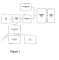
- Figure 1 illustrates an exemplary parallel hybrid electric vehicle management system according to the invention
- FIGS 2 and 3 illustrate flow charts for managing power supplied to an electric motor according to the invention.
- FIG. 1 illustrates an example of a parallel hybrid electric vehicle management system (parallel hybrid vehicle or HEV) 1 according to the invention.
- the parallel hybrid vehicle 1 includes two parallel power paths: a first path including an internal combustion engine 130 (hereinafter "engine”) and a second path including electric motor 105.
- the engine 130 is of a conventional type that uses gasoline, diesel, bio-diesel, compressed natural gas (CNG), or other conventional fuel for initiating and sustaining combustion in one or more combustion chambers.
- CNG compressed natural gas
- the workings of the engine 130 are well known in the art, the present disclosure will forego providing a detailed description of the operation of the engine 130 herein for brevity.
- the engine 130 is mechanically coupled to a transmission system 135.
- the transmission system 135 provides driver-controlled or vehicle computer-controlled gear ratio selection from among at least one gear ratio depending on velocity, torque and acceleration requirements.
- the electric motor/generator 105 receives electrical energy from energy storage device (ESD) 100, such as Lithium-Ion batteries, or other energy storage technologies capable of providing the necessary electrical power to the electric motor/generator 105.
- ESD energy storage device
- a motor controller 115 is provided to control the operation of the electric motor/generator 105.
- the motor controller 115 includes an inverter that converts the DC power from the ESD 100 into AC power for the motor/generator 105.
- the motor controller 115 is programmed with a program for executing control over the motor/generator 105.
- a system controller 110 controls the HEV 1.
- the system controller 110 determines the torque sharing or apportioning between each of the parallel paths, i.e., the amount of torque provided by the engine 130 and the motor/generator 105. Additionally, the system controller 110 provides feedback control for the torque sharing based upon a trend of the SOC for the ESD 100.
- the motor controller 115 receives the torque command from the system controller 110 and controls the motor/generator 105 to the specified torque.
- the system controller 110 is programmed with a torque sharing method used to respond to a driver torque command, using a combination of the torque from the motor/generator 105 and the engine 130.
- the torque for the motor/generator 105 determined by the torque sharing method is adjusted by the system controller 110 using a feedback correction factor (which also effectively adjusts the torque of the engine).
- the feedback correction factor is used to allow the SOC of the ESD 100 to vary instantaneously over a predetermined reference range, but remain within this reference range over a drive cycle.
- the system controller 110 adjusts a baseline torque sharing (determined by a torque sharing method) for both the motor/generator 105 and engine 130 using the feedback correction factor. For example, if the feedback correction factor indicates that the motor/generator 105 should use more energy, the torque determined for the motor/generator 105 will increase and/or command motor torque more often. On the other hand, if the feedback correction factor indicates that the motor/generator 105 should conserve energy, the torque determined for the motor/generator 105 will decrease and/or command motor torque less often. In other words, the instantaneous power or duration thereof supplied by the motor/generator 105 is adjusted.
- a baseline torque sharing determined by a torque sharing method
- the engine 130 can have a separate engine controller (not shown) which controls the torque of the engine in response to a torque command.
- the ESD 100 is configured to provide a voltage output adequate to drive the electric motor/generator 105 via the motor controller 115.
- the voltage output from the battery can be in the hundreds of volts, for example 325 Volts DC.
- the system controller 110 is responsive to a torque command received from a driver via a user interface 120 such as an accelerator pedal or a brake command from the brake 125.
- the motor controller 115 commands a negative torque from the motor/generator 105.
- this configuration allows the electric motor/generator 105 to operate as an electric generator in order to recoup regenerative braking energy for recharging the ESD 100.
- the ESD 100 is charged by only using energy recouped from regenerative braking, and no power from the engine 130 is used to charge the ESD 100.
- the system controller 110 continuously monitors a State of charge (SOC) of the ESD 100 and outputs a feedback correction factor to adjust the torque of the motor/generator 105 and engine 130 based upon the net energy flow (SOC) trend of the HEV 1.
- the system controller 110 includes a processing section and memory (both volatile and non-volatile memory).
- the system controller memory contains a program to determine a reference SOC value.
- a default reference SOC value is also stored in the memory.
- the reference SOC value can be constant, i.e., a specific reference point or a reference range having a upper and lower tolerance, i.e., operating zone.
- a specified constant reference SOC can vary based upon various factors, which can include, but is not limited to, type of vehicle, vehicle weight or type of ESD 110.
- the reference SOC can also be calculated using a reference plant model of the entire vehicle or subsystem of the vehicle. A reference plant model is known and will not be described herein in detail.
- the system controller 110 determines a feedback correction factor using a determined error which is based on the difference between the current SOC and reference SOC range.
- the feedback correction factor represents whether the parallel hybrid vehicle 1 is trying to conserve or use more energy from the ESD 100.
- the feedback correction factor allows the actual SOC to vary within the entire reference SOC range in short periods of time, but adjust motor torque so that there is no net SOC increase/decrease over a long period of time on the same drive cycle.
- the feedback correction factor will vary over time; however, the variance will decrease and eventually stabilize.
- the feedback correction factor is stored in the system controller memory, either continuously or during shutdown. Upon startup or reset, the system controller 110 can initialize the feedback correction factor to one of the stored feedback correction factors.
- Figures 2 and 3 illustrate a method of managing the SOC of the ESD 100 and controlling the torque of the motor and engine in accordance with the invention.
- the SOC is calculated.
- the calculation is based upon battery parameters such as voltage or current.
- the calculated SOC is given as a percentage of full capacity. This calculation is continuously performed as the SOC is in constant flux due to discharge/charge of the ESD 100 depending on the operational mode of the motor/generator 105.
- the reference SOC is determined by being calculated or retrieved from memory. As noted above, the reference SOC can be a reference range.
- the system controller 110 determines an error from the difference between the calculated SOC (from step 200) and the reference SOC (from step 205).
- the system controller 110 determines a feedback correction factor using the error determined at step 207. The determination of the feedback correction factor will be described later in detail with respect to Figure 3 .
- the feedback correction factor is used by the system controller 110 to adjust the apportioning of torque between the motor/generator 105 and engine 130.
- the system controller 110 determines if a change in the drive torque demand or command was received via the user interface 120. If no change in the drive torque command was received, the total torque needed to satisfy the demand remains the same. Therefore, the torque sharing for the motor/generator 105 and engine 130 is only determined based upon the feedback correction factor, at step 225. If the feedback correction factor indicates that there was a net surplus in electrical energy (the SOC is at the high end or above the reference SOC), then the system controller 110 will increase the torque command to the motor controller 115. In other words, the system controller 110 will increase the torque sharing ratio of motor power to engine power or increase the duration of motor torque.
- the system controller 110 will decrease the torque command to the motor controller 115. In other words, the system controller 110 will decrease the torque sharing ratio of motor power to engine power or decrease the duration of motor torque.
- the motor/generator 105 only uses energy that has been previously recaptured through regenerative braking to yield a charge sustaining torque sharing method.
- system controller 110 determines the torque ratio needed to satisfy the new torque command, i.e., the change in total torque.
- the motor power/torque and/or duration of the motor torque will be adjusted based upon both the feedback correction factor and the new torque command, at step 220.
- the determined torque ratio is a baseline ratio.
- the baseline ratio is adjusted using the feedback correction factor. If the feedback correction factor indicates that there is a surplus in electrical energy(as a result of having more charging of the battery via regenerative energy than discharging of the battery for powering the motor/generator 105, such that the SOC is at the high end or above the reference SOC range), then system controller 110 will increase the torque command to the motor controller 115, which will supply more power to the motor/generator 105 than would have been used, i.e., increase a baseline motor torque and decrease the engine power.
- the system controller 110 will decrease the torque command to the motor controller 115, which will supply less power to the motor/generator 105 than that would have been used, i.e., decrease the baseline motor torque and increase engine power. In this manner, maximum fuel efficiency for the vehicle, and extended life of the ESD 100 can be attained.
- system controller 110 is used to control the torque ratio and torque of both the motor/generator 105 and engine 130; however, a separate engine controller can be used to control the engine 130.
- Figure 3 illustrates a flow chart for determining the feedback correction factor.
- the system controller 110 determines if a vehicle has just been turned on, i.e., the timing in the drive cycle. As noted above, the system controller 110 stores a previously determined feedback correction factor in memory. When the vehicle is turned back on, the system controller 110 can initialize the feedback correction factor to whatever value it was before the vehicle was turned off, at step 305. The stored feedback correction factor is retrieved from memory and is set as the new feedback correction factor. This is particularly useful to vehicles that drive the same type of drive cycle each day. If the vehicle was not just turned on, the system controller 110 determines if an initial reset condition exists, at step 310. The initial resist condition can be an internal reset or an external reset.
- a default feedback correction factor is retrieved from memory (at step 315) and is used as the new feedback correction factor.
- the default feedback correction factor can be based upon a current vehicle parameter such as speed, estimated battery life, drive cycle conditions and/or an input from the driver.
- a driver can control the HEV 1 to use one of the stored feedback correction factors via the user interface 120.
- the driver may issue a reset to signal the system controller 110 to select a specific feedback correction factor based upon a type of drive cycle.
- the driver can inform the system controller 110 that the drive cycle has changed, e.g., city driving to highway driving and that the feedback correction factor should be reset to the stored feedback correction factor for the new type of drive cycle.
- Each of the stored feedback correction factors can be stored with an identifier.
- the identifier can be associated with a type of drive cycle. Therefore, when the driver inputs a reset with an identification of a drive cycle via the user interface 120, the system controller 110 can retrieve the associated feedback correction factor.
- the determined drive cycle and other reset criterion can occur internal to the system controller 110.
- the system controller 110 monitors the stability of the feedback correction factor. Once the feedback correction factor becomes stable, the system controller 110 will store the feedback correction factor for the specified drive cycle in memory as the default feedback correction factor for the drive cycle for later use.
- variable control loop gains can be customized for the type of vehicle, weight, type of battery, etc. Additionally, the variable control loop gains can be adjusted based upon real time parameters such as, but not limited to, an estimated battery life.
- the system controller 110 determines if the variable control loop gains need to be adjusted based upon continuously monitored current real time parameters. If the variable control loop gains need to be adjusted, they are adjusted at step 335.
- the feedback correction factor is calculated using the variable control loop gains and the error.
- the adjusted feedback correction factor is calculated using the adjusted variable control loop gains and the error.
- the calculated feedback correction factor is stored in memory.
- the present invention may be embodied as a system, method or computer program product. Accordingly, the present invention may take the form of an entirely hardware embodiment, an entirely software embodiment (including firmware, resident software, micro-code, etc.) or an embodiment combining software and hardware aspects that may all generally be referred to herein as "system.”
- aspects of the present invention may be embodied as a program, software, or computer instructions embodied in a computer or machine usable or readable medium, which causes the computer or machine to perform the steps of the method(s) disclosed herein when executed on the computer, processor, and/or machine.
- a program storage device readable by a machine, tangibly embodying a program of instructions executable by the machine to perform various functionalities and methods described in the present disclosure is also provided.
- the system and method of the present invention may be implemented and run on a general-purpose computer or special-purpose computer system.
- the computer system may be any type of known or will be known systems.
Landscapes
- Engineering & Computer Science (AREA)
- Transportation (AREA)
- Mechanical Engineering (AREA)
- Chemical & Material Sciences (AREA)
- Combustion & Propulsion (AREA)
- Automation & Control Theory (AREA)
- Electric Propulsion And Braking For Vehicles (AREA)
- Hybrid Electric Vehicles (AREA)
Applications Claiming Priority (1)
| Application Number | Priority Date | Filing Date | Title |
|---|---|---|---|
| US13/205,191 US8612078B2 (en) | 2011-08-08 | 2011-08-08 | Parallel hybrid electric vehicle power management system and adaptive power management method and program therefor |
Publications (2)
| Publication Number | Publication Date |
|---|---|
| EP2557009A2 true EP2557009A2 (fr) | 2013-02-13 |
| EP2557009A3 EP2557009A3 (fr) | 2018-05-02 |
Family
ID=46679183
Family Applications (1)
| Application Number | Title | Priority Date | Filing Date |
|---|---|---|---|
| EP12179640.3A Withdrawn EP2557009A3 (fr) | 2011-08-08 | 2012-08-08 | Système de gestion de l'énergie électrique d'un véhicule électrique hybride parallèle et procédé adaptatif de gestion de l'énergie électrique et programme associé |
Country Status (7)
| Country | Link |
|---|---|
| US (2) | US8612078B2 (fr) |
| EP (1) | EP2557009A3 (fr) |
| JP (1) | JP2013035545A (fr) |
| CN (1) | CN102923123A (fr) |
| AU (1) | AU2012203534B2 (fr) |
| BR (1) | BR102012017685A2 (fr) |
| CA (1) | CA2779587C (fr) |
Families Citing this family (19)
| Publication number | Priority date | Publication date | Assignee | Title |
|---|---|---|---|---|
| CN103354790B (zh) * | 2011-02-09 | 2016-04-06 | 铃木株式会社 | 混合动力车辆的驱动控制设备及混合动力车辆 |
| CN103732462B (zh) * | 2011-08-08 | 2016-09-07 | 丰田自动车株式会社 | 车辆、车辆的控制方法以及车辆的控制装置 |
| GB2517685B (en) * | 2013-08-21 | 2017-10-25 | Jaguar Land Rover Ltd | Vehicle controller and method |
| JP6500368B2 (ja) * | 2014-08-27 | 2019-04-17 | 三菱自動車工業株式会社 | ハイブリッド車両の回生制御装置 |
| CN105730438B (zh) * | 2014-12-09 | 2018-05-11 | 北汽福田汽车股份有限公司 | 一种用于串联式混合动力汽车的能量分配方法和装置 |
| KR101724463B1 (ko) | 2015-06-29 | 2017-04-07 | 현대자동차 주식회사 | 하이브리드 차량의 충전 상태 제어 장치 및 방법 |
| CN105128855B (zh) * | 2015-09-21 | 2017-07-21 | 大连理工大学 | 一种双轴并联混合动力城市公交车的控制方法 |
| US10112595B2 (en) | 2016-11-08 | 2018-10-30 | Hyundai America Technical Center, Inc | Predictive control of powertrain systems based on vehicle-to-vehicle (V2V) communications |
| US11453382B2 (en) * | 2017-05-01 | 2022-09-27 | Cummins Inc. | Systems and methods for controlling energy generation in a hybrid powertrain |
| CN109613432A (zh) * | 2019-01-08 | 2019-04-12 | 广州小鹏汽车科技有限公司 | 估算电池荷电状态的方法、设备及计算机可读存储介质 |
| CN109747678B (zh) * | 2019-01-11 | 2020-05-15 | 泰州禾益新材料科技有限公司 | 一种动车用非接触式制动装置 |
| US11097721B1 (en) * | 2020-03-31 | 2021-08-24 | Ford Global Technologies, Llc | Methods and system for modulating torque during a transmission gear shift |
| US20220138667A1 (en) * | 2020-11-03 | 2022-05-05 | Toyota Motor North America, Inc. | Managing transport data expiration |
| CN112758095B (zh) * | 2021-01-11 | 2022-07-01 | 安徽华菱汽车有限公司 | 能量控制方法、制动能量回馈系统及计算机可读存储介质 |
| CN115230674B (zh) * | 2021-05-07 | 2023-11-17 | 广州汽车集团股份有限公司 | 混合动力汽车驱动控制方法以及混合动力汽车 |
| KR102572840B1 (ko) * | 2021-12-10 | 2023-08-31 | 주식회사 현대케피코 | 하이브리드 차량의 엔진 및 모터의 출력 토크를 분배하는 제어 시스템 및 그 동작 방법 |
| CN114035064B (zh) * | 2021-12-20 | 2024-06-18 | 武汉蔚能电池资产有限公司 | 一种电池电荷状态校正方法、装置、车辆及存储介质 |
| CN114312742B (zh) * | 2022-01-27 | 2024-10-11 | 重庆金康动力新能源有限公司 | 一种行车发电控制方法、装置、存储介质和整车控制器 |
| CN117341535B (zh) * | 2023-12-04 | 2024-02-06 | 四川鼎鸿智电装备科技有限公司 | 一种智能电动工程机械能量管理方法和系统 |
Citations (1)
| Publication number | Priority date | Publication date | Assignee | Title |
|---|---|---|---|---|
| US20080203966A1 (en) * | 2007-02-23 | 2008-08-28 | Thomas Allan Ward | Current limiting parallel battery charging system to enable plug-in or solar power to supplement regenerative braking in hybrid or electric vehicle |
Family Cites Families (43)
| Publication number | Priority date | Publication date | Assignee | Title |
|---|---|---|---|---|
| US5842534A (en) | 1995-05-31 | 1998-12-01 | Frank; Andrew A. | Charge depletion control method and apparatus for hybrid powered vehicles |
| US6116363A (en) | 1995-05-31 | 2000-09-12 | Frank Transportation Technology, Llc | Fuel consumption control for charge depletion hybrid electric vehicles |
| US5667029A (en) | 1995-05-31 | 1997-09-16 | New York Institute Of Technology | Drive system for hybrid electric vehicle |
| US6018694A (en) * | 1996-07-30 | 2000-01-25 | Denso Corporation | Controller for hybrid vehicle |
| US5820172A (en) | 1997-02-27 | 1998-10-13 | Ford Global Technologies, Inc. | Method for controlling energy flow in a hybrid electric vehicle |
| JP3454133B2 (ja) * | 1998-01-16 | 2003-10-06 | トヨタ自動車株式会社 | ハイブリッド車の駆動制御装置 |
| US6554088B2 (en) | 1998-09-14 | 2003-04-29 | Paice Corporation | Hybrid vehicles |
| EP1125781B1 (fr) | 2000-01-24 | 2004-03-24 | Hino Jidosha Kabushiki Kaisha | Véhicule hybride |
| GB2367795B (en) | 2000-10-11 | 2004-07-14 | Ford Motor Co | A control system for a hybrid electric vehicle |
| US6500089B2 (en) | 2000-10-31 | 2002-12-31 | Ford Global Technologies, Inc. | Method and arrangement in a hybrid vehicle for maximizing efficiency by operating the engine at sub-optimum conditions |
| US6512967B2 (en) | 2000-10-31 | 2003-01-28 | Volvo Car Corporation | Method and arrangement in a hybrid vehicle for maximizing total torque output by minimizing differential torque capacities of the engine and generator |
| US6453222B1 (en) | 2000-10-31 | 2002-09-17 | Volvo Car Corporation | Method and arrangement in a hybrid vehicle for matching engine and generator torques at times of engagement and disengagement |
| JP2004248382A (ja) * | 2003-02-12 | 2004-09-02 | Mitsubishi Motors Corp | ハイブリッド車 |
| US6987330B2 (en) | 2003-04-16 | 2006-01-17 | Ford Global Technologies, Llc | Method and system for controlling a belt-driven integrated starter generator |
| JP3933106B2 (ja) * | 2003-07-30 | 2007-06-20 | トヨタ自動車株式会社 | 動力出力装置およびその制御方法並びに自動車 |
| US7200476B2 (en) | 2003-10-14 | 2007-04-03 | General Motors Corporation | Optimal selection of input torque considering battery utilization for a hybrid electric vehicle |
| US20060016627A1 (en) | 2004-07-22 | 2006-01-26 | Harold Robertson | Bifurcated electrical vehicle motor |
| US7370715B2 (en) | 2004-12-28 | 2008-05-13 | Ford Global Technologies, Llc | Vehicle and method for controlling engine start in a vehicle |
| JP4301197B2 (ja) * | 2005-04-22 | 2009-07-22 | トヨタ自動車株式会社 | 車両の制御装置 |
| JP2007126081A (ja) | 2005-11-07 | 2007-05-24 | Nissan Motor Co Ltd | ハイブリッド車両のクラッチ伝達トルク容量制御装置 |
| DE112007000047A5 (de) * | 2006-03-20 | 2008-08-28 | Temic Automotive Electric Motors Gmbh | Hybridfahrzeug |
| EP2025904B1 (fr) * | 2006-06-07 | 2016-06-01 | Toyota Jidosha Kabushiki Kaisha | Véhicule hybride |
| WO2008016357A2 (fr) * | 2006-08-02 | 2008-02-07 | Mack Trucks, Inc. | Système de gestion de puissance pour un véhicule, procédé de gestion de puissance du véhicule et procédé pour installer un système de gestion de puissance de véhicule |
| JP4202379B2 (ja) * | 2006-10-11 | 2008-12-24 | トヨタ自動車株式会社 | ハイブリッド車両、ハイブリッド車両の制御方法、その制御方法をコンピュータに実行させるためのプログラム、およびそのプログラムを記録したコンピュータ読み取り可能な記録媒体 |
| JP5234396B2 (ja) | 2006-11-13 | 2013-07-10 | 現代自動車株式会社 | ハイブリッド電気車両のエンジン停止位置の制御方法 |
| US8234025B2 (en) * | 2006-11-28 | 2012-07-31 | GM Global Technology Operations LLC | Control system for a hybrid powertrain system |
| US7967711B2 (en) | 2006-11-28 | 2011-06-28 | GM Global Technology Operations LLC | Highly configurable hybrid powertrain and control system therefor |
| JP5076516B2 (ja) | 2007-01-24 | 2012-11-21 | 日産自動車株式会社 | ハイブリッド車両の変速時モード切り替え制御装置 |
| US20080185198A1 (en) | 2007-02-02 | 2008-08-07 | Steven Mark Jones | Next generation hybrid III parallel/series hybrid system |
| JP4872743B2 (ja) * | 2007-03-23 | 2012-02-08 | トヨタ自動車株式会社 | 二次電池の状態推定装置 |
| JP4379484B2 (ja) * | 2007-04-06 | 2009-12-09 | 株式会社デンソー | 車両システム |
| JP5109467B2 (ja) | 2007-05-02 | 2012-12-26 | 日産自動車株式会社 | ハイブリッド車両の駆動制御装置 |
| US7774109B2 (en) | 2007-09-19 | 2010-08-10 | Gm Global Technology Operations, Inc. | Method and apparatus for managing torque inputs to an electro-mechanical transmission |
| US9579961B2 (en) * | 2007-09-24 | 2017-02-28 | Scott C Harris | Hybrid vehicle with modular battery system |
| US7837593B2 (en) | 2007-11-12 | 2010-11-23 | Ford Global Technologies, Llc | Method and system for using mechanical power to operate a hybrid electric vehicle |
| US7691027B2 (en) * | 2007-11-29 | 2010-04-06 | Ford Global Technologies, Llc | Idle speed control of a hybrid electric vehicle |
| KR100992635B1 (ko) * | 2007-12-13 | 2010-11-05 | 현대자동차주식회사 | 하이브리드 차량의 운전자 요구 토크 제어 방법 |
| JP5314906B2 (ja) * | 2008-02-29 | 2013-10-16 | ニチユ三菱フォークリフト株式会社 | 作業用車両の制御方法および作業用車両 |
| JP4525809B2 (ja) * | 2008-07-28 | 2010-08-18 | トヨタ自動車株式会社 | 電源システムおよびそれを備えた車両、ならびに電源システムの制御方法 |
| JP4649682B2 (ja) * | 2008-09-02 | 2011-03-16 | 株式会社豊田中央研究所 | 二次電池の状態推定装置 |
| US20110089904A1 (en) * | 2008-12-04 | 2011-04-21 | Thomas Allan Ward | Current clamping parallel battery charging system to supplement regenerative braking in electric vehicle |
| US8359133B2 (en) * | 2010-02-19 | 2013-01-22 | Ford Global Technologies, Llc | Engine power elevation and active battery charge energy management strategies for plug-in hybrid electric vehicles |
| JP5472048B2 (ja) * | 2010-11-10 | 2014-04-16 | 株式会社デンソー | 車載2次電池の状態定量化装置 |
-
2011
- 2011-08-08 US US13/205,191 patent/US8612078B2/en active Active
-
2012
- 2012-06-08 CA CA2779587A patent/CA2779587C/fr active Active
- 2012-06-18 AU AU2012203534A patent/AU2012203534B2/en active Active
- 2012-07-17 BR BRBR102012017685-8A patent/BR102012017685A2/pt not_active IP Right Cessation
- 2012-08-07 JP JP2012175294A patent/JP2013035545A/ja active Pending
- 2012-08-08 CN CN201210280951XA patent/CN102923123A/zh active Pending
- 2012-08-08 EP EP12179640.3A patent/EP2557009A3/fr not_active Withdrawn
-
2013
- 2013-12-16 US US14/107,706 patent/US20140107879A1/en not_active Abandoned
Patent Citations (1)
| Publication number | Priority date | Publication date | Assignee | Title |
|---|---|---|---|---|
| US20080203966A1 (en) * | 2007-02-23 | 2008-08-28 | Thomas Allan Ward | Current limiting parallel battery charging system to enable plug-in or solar power to supplement regenerative braking in hybrid or electric vehicle |
Also Published As
| Publication number | Publication date |
|---|---|
| CN102923123A (zh) | 2013-02-13 |
| CA2779587C (fr) | 2019-01-15 |
| JP2013035545A (ja) | 2013-02-21 |
| US8612078B2 (en) | 2013-12-17 |
| AU2012203534A1 (en) | 2013-02-28 |
| US20140107879A1 (en) | 2014-04-17 |
| AU2012203534B2 (en) | 2015-01-22 |
| BR102012017685A2 (pt) | 2013-07-16 |
| CA2779587A1 (fr) | 2013-02-08 |
| EP2557009A3 (fr) | 2018-05-02 |
| US20130041530A1 (en) | 2013-02-14 |
Similar Documents
| Publication | Publication Date | Title |
|---|---|---|
| US8612078B2 (en) | Parallel hybrid electric vehicle power management system and adaptive power management method and program therefor | |
| US8022674B2 (en) | State of charge control method and systems for vehicles | |
| US7917276B2 (en) | Vehicle-use power supply apparatus | |
| JP5688920B2 (ja) | ハイブリッド車両のバッテリーsocのバランシング制御方法 | |
| CN102556053B (zh) | 用于控制发动机扭矩的系统和方法 | |
| WO2012039167A1 (fr) | Dispositif de commande de production d'énergie électrique pour un véhicule électrique | |
| JP2004527193A (ja) | ハイブリッド電気自動車の動作特性の制御方法 | |
| JP2011234487A (ja) | 電動車両の制御装置 | |
| JP5251957B2 (ja) | 充電制御装置 | |
| KR20130068411A (ko) | 하이브리드 자동차의 배터리 충방전 제어방법 | |
| KR20200061664A (ko) | 플러그인 하이브리드 자동차 및 그를 위한 충전 제어 방법 | |
| US7308958B2 (en) | Method for controlling a series hybrid electric vehicle | |
| CN104302526B (zh) | 用于对内燃机进行控制的方法和装置 | |
| JP5419745B2 (ja) | シリーズハイブリッド車両の制御装置 | |
| CN103036448A (zh) | 有源开关频率调制 | |
| JP5445702B2 (ja) | 充電制御装置 | |
| JP2013035302A (ja) | ハイブリッド車 | |
| JP6270010B2 (ja) | 車両の電力制御装置 | |
| JP2016124481A (ja) | 車両用電源制御装置 | |
| CN115027444B (zh) | 车辆的转速控制方法、装置及计算机可读存储介质 | |
| CN111114531A (zh) | 基于p2结构混合动力系统的坡行方法及控制系统 | |
| US12344254B2 (en) | Control method for vehicle and control device for vehicle | |
| JP5699841B2 (ja) | ハイブリッド自動車 | |
| CN120621166A (zh) | 燃料电池的输出功率控制方法、系统、设备及存储介质 | |
| JP2010220350A (ja) | 発電制御装置、及び発電制御方法 |
Legal Events
| Date | Code | Title | Description |
|---|---|---|---|
| PUAI | Public reference made under article 153(3) epc to a published international application that has entered the european phase |
Free format text: ORIGINAL CODE: 0009012 |
|
| AK | Designated contracting states |
Kind code of ref document: A2 Designated state(s): AL AT BE BG CH CY CZ DE DK EE ES FI FR GB GR HR HU IE IS IT LI LT LU LV MC MK MT NL NO PL PT RO RS SE SI SK SM TR |
|
| AX | Request for extension of the european patent |
Extension state: BA ME |
|
| RAP1 | Party data changed (applicant data changed or rights of an application transferred) |
Owner name: BAE SYSTEMS CONTROLS INC. |
|
| PUAL | Search report despatched |
Free format text: ORIGINAL CODE: 0009013 |
|
| AK | Designated contracting states |
Kind code of ref document: A3 Designated state(s): AL AT BE BG CH CY CZ DE DK EE ES FI FR GB GR HR HU IE IS IT LI LT LU LV MC MK MT NL NO PL PT RO RS SE SI SK SM TR |
|
| AX | Request for extension of the european patent |
Extension state: BA ME |
|
| RIC1 | Information provided on ipc code assigned before grant |
Ipc: B60K 6/48 20071001ALI20180323BHEP Ipc: B60W 10/06 20060101ALI20180323BHEP Ipc: B60W 10/26 20060101ALI20180323BHEP Ipc: B60W 10/08 20060101ALI20180323BHEP Ipc: B60W 20/00 20060101AFI20180323BHEP |
|
| STAA | Information on the status of an ep patent application or granted ep patent |
Free format text: STATUS: REQUEST FOR EXAMINATION WAS MADE |
|
| 17P | Request for examination filed |
Effective date: 20181024 |
|
| RBV | Designated contracting states (corrected) |
Designated state(s): AL AT BE BG CH CY CZ DE DK EE ES FI FR GB GR HR HU IE IS IT LI LT LU LV MC MK MT NL NO PL PT RO RS SE SI SK SM TR |
|
| RIC1 | Information provided on ipc code assigned before grant |
Ipc: B60K 6/48 20071001ALI20180323BHEP Ipc: B60W 10/26 20060101ALI20180323BHEP Ipc: B60W 10/06 20060101ALI20180323BHEP Ipc: B60W 20/00 20160101AFI20180323BHEP Ipc: B60W 10/08 20060101ALI20180323BHEP |
|
| STAA | Information on the status of an ep patent application or granted ep patent |
Free format text: STATUS: EXAMINATION IS IN PROGRESS |
|
| 17Q | First examination report despatched |
Effective date: 20200507 |
|
| GRAP | Despatch of communication of intention to grant a patent |
Free format text: ORIGINAL CODE: EPIDOSNIGR1 |
|
| STAA | Information on the status of an ep patent application or granted ep patent |
Free format text: STATUS: GRANT OF PATENT IS INTENDED |
|
| INTG | Intention to grant announced |
Effective date: 20201217 |
|
| STAA | Information on the status of an ep patent application or granted ep patent |
Free format text: STATUS: THE APPLICATION IS DEEMED TO BE WITHDRAWN |
|
| 18D | Application deemed to be withdrawn |
Effective date: 20210429 |