EP2557769A1 - Bildsensoreinheit und Bildlesevorrichtung - Google Patents
Bildsensoreinheit und Bildlesevorrichtung Download PDFInfo
- Publication number
- EP2557769A1 EP2557769A1 EP12179608A EP12179608A EP2557769A1 EP 2557769 A1 EP2557769 A1 EP 2557769A1 EP 12179608 A EP12179608 A EP 12179608A EP 12179608 A EP12179608 A EP 12179608A EP 2557769 A1 EP2557769 A1 EP 2557769A1
- Authority
- EP
- European Patent Office
- Prior art keywords
- light
- reading
- light guide
- transmission
- image
- Prior art date
- Legal status (The legal status is an assumption and is not a legal conclusion. Google has not performed a legal analysis and makes no representation as to the accuracy of the status listed.)
- Withdrawn
Links
- 230000000903 blocking effect Effects 0.000 claims abstract description 94
- 238000003384 imaging method Methods 0.000 claims abstract description 11
- 238000005286 illumination Methods 0.000 claims description 83
- 230000003287 optical effect Effects 0.000 claims description 24
- 239000012788 optical film Substances 0.000 claims description 4
- 230000005540 biological transmission Effects 0.000 abstract description 147
- 239000006059 cover glass Substances 0.000 description 17
- 102100027340 Slit homolog 2 protein Human genes 0.000 description 15
- 101710133576 Slit homolog 2 protein Proteins 0.000 description 15
- 229910052732 germanium Inorganic materials 0.000 description 11
- GNPVGFCGXDBREM-UHFFFAOYSA-N germanium atom Chemical compound [Ge] GNPVGFCGXDBREM-UHFFFAOYSA-N 0.000 description 11
- 230000007423 decrease Effects 0.000 description 7
- 238000004088 simulation Methods 0.000 description 7
- 239000010408 film Substances 0.000 description 6
- 230000000694 effects Effects 0.000 description 5
- 238000003708 edge detection Methods 0.000 description 3
- 239000000758 substrate Substances 0.000 description 3
- 239000004925 Acrylic resin Substances 0.000 description 2
- 229920000178 Acrylic resin Polymers 0.000 description 2
- 230000009471 action Effects 0.000 description 2
- 230000008901 benefit Effects 0.000 description 2
- 238000006243 chemical reaction Methods 0.000 description 2
- 239000003086 colorant Substances 0.000 description 2
- 238000001514 detection method Methods 0.000 description 2
- 230000008595 infiltration Effects 0.000 description 2
- 238000001764 infiltration Methods 0.000 description 2
- 230000031700 light absorption Effects 0.000 description 2
- 239000000463 material Substances 0.000 description 2
- 229920000515 polycarbonate Polymers 0.000 description 2
- 239000004417 polycarbonate Substances 0.000 description 2
- 230000000644 propagated effect Effects 0.000 description 2
- 239000011347 resin Substances 0.000 description 2
- 229920005989 resin Polymers 0.000 description 2
- 239000012780 transparent material Substances 0.000 description 2
- 230000004075 alteration Effects 0.000 description 1
- 230000003321 amplification Effects 0.000 description 1
- 238000005516 engineering process Methods 0.000 description 1
- 230000007246 mechanism Effects 0.000 description 1
- 230000004048 modification Effects 0.000 description 1
- 238000012986 modification Methods 0.000 description 1
- 238000003199 nucleic acid amplification method Methods 0.000 description 1
- 230000035945 sensitivity Effects 0.000 description 1
Images






Classifications
-
- H—ELECTRICITY
- H04—ELECTRIC COMMUNICATION TECHNIQUE
- H04N—PICTORIAL COMMUNICATION, e.g. TELEVISION
- H04N1/00—Scanning, transmission or reproduction of documents or the like, e.g. facsimile transmission; Details thereof
- H04N1/024—Details of scanning heads ; Means for illuminating the original
- H04N1/028—Details of scanning heads ; Means for illuminating the original for picture information pick-up
- H04N1/02815—Means for illuminating the original, not specific to a particular type of pick-up head
- H04N1/0282—Using a single or a few point light sources, e.g. a laser diode
-
- H—ELECTRICITY
- H04—ELECTRIC COMMUNICATION TECHNIQUE
- H04N—PICTORIAL COMMUNICATION, e.g. TELEVISION
- H04N25/00—Circuitry of solid-state image sensors [SSIS]; Control thereof
-
- G—PHYSICS
- G07—CHECKING-DEVICES
- G07D—HANDLING OF COINS OR VALUABLE PAPERS, e.g. TESTING, SORTING BY DENOMINATIONS, COUNTING, DISPENSING, CHANGING OR DEPOSITING
- G07D7/00—Testing specially adapted to determine the identity or genuineness of valuable papers or for segregating those which are unacceptable, e.g. banknotes that are alien to a currency
- G07D7/06—Testing specially adapted to determine the identity or genuineness of valuable papers or for segregating those which are unacceptable, e.g. banknotes that are alien to a currency using wave or particle radiation
- G07D7/12—Visible light, infrared or ultraviolet radiation
- G07D7/121—Apparatus characterised by sensor details
-
- H—ELECTRICITY
- H04—ELECTRIC COMMUNICATION TECHNIQUE
- H04N—PICTORIAL COMMUNICATION, e.g. TELEVISION
- H04N1/00—Scanning, transmission or reproduction of documents or the like, e.g. facsimile transmission; Details thereof
- H04N1/024—Details of scanning heads ; Means for illuminating the original
- H04N1/028—Details of scanning heads ; Means for illuminating the original for picture information pick-up
-
- H—ELECTRICITY
- H04—ELECTRIC COMMUNICATION TECHNIQUE
- H04N—PICTORIAL COMMUNICATION, e.g. TELEVISION
- H04N2201/00—Indexing scheme relating to scanning, transmission or reproduction of documents or the like, and to details thereof
- H04N2201/0077—Types of the still picture apparatus
- H04N2201/0081—Image reader
-
- H—ELECTRICITY
- H04—ELECTRIC COMMUNICATION TECHNIQUE
- H04N—PICTORIAL COMMUNICATION, e.g. TELEVISION
- H04N2201/00—Indexing scheme relating to scanning, transmission or reproduction of documents or the like, and to details thereof
- H04N2201/024—Indexing scheme relating to scanning, transmission or reproduction of documents or the like, and to details thereof deleted
- H04N2201/028—Indexing scheme relating to scanning, transmission or reproduction of documents or the like, and to details thereof deleted for picture information pick-up
- H04N2201/03—Indexing scheme relating to scanning, transmission or reproduction of documents or the like, and to details thereof deleted for picture information pick-up deleted
- H04N2201/031—Indexing scheme relating to scanning, transmission or reproduction of documents or the like, and to details thereof deleted for picture information pick-up deleted deleted
- H04N2201/03104—Integral pick-up heads, i.e. self-contained heads whose basic elements are a light source, a lens and a photodetector supported by a single-piece frame
- H04N2201/0315—Details of integral heads not otherwise provided for
- H04N2201/03166—Additional light shielding member
-
- H—ELECTRICITY
- H04—ELECTRIC COMMUNICATION TECHNIQUE
- H04N—PICTORIAL COMMUNICATION, e.g. TELEVISION
- H04N2201/00—Indexing scheme relating to scanning, transmission or reproduction of documents or the like, and to details thereof
- H04N2201/04—Scanning arrangements
- H04N2201/0402—Arrangements not specific to a particular one of the scanning methods covered by groups H04N1/04 - H04N1/207
- H04N2201/0418—Arrangements not specific to a particular one of the scanning methods covered by groups H04N1/04 - H04N1/207 capable of scanning transmissive and reflective originals at a single scanning station
Definitions
- the present invention relates to an image sensor unit used in an image reading apparatus such as a copying machine, image scanner, facsimile and so on, and the image reading apparatus using the image sensor unit.
- the present invention relates to an image reading apparatus that authenticates a recording medium, such as a bill, security and so on.
- Patent Document 1 an apparatus disclosed in Patent Document 1 is known as an image reading apparatus that, in particular, authenticates a bill, security and so on.
- the stray light (reflection light that is described later) becomes a noise component in the output of the image sensor unit, and a difference between an output signal (signal component) when an original is present and the noise component produced by the stray light decreases, and this leads to problems such as the contrast becoming blurred and a decrease in the accuracy of a read image.
- the present invention has been made in view of the above described situation, and an object of the present invention is to provide an image sensor unit and an image reading apparatus that can improve the accuracy of a read image by reducing the influence of stray light.
- an image sensor unit that performs image reading by reflected light and image reading by transmitted light with respect to an object of illumination, comprising: a first light guide that emits light from a first light source toward the object of illumination; a second light guide that emits light from a second light source toward the object of illumination; an imaging element that focuses light from the object of illumination; and a light receiving element that converts light that is collected by the imaging element into an electric signal, wherein the second light source and the second light guide are disposed on opposite sides of a conveyance path through which the object of illumination can pass, and light blocking means that blocks at least a part of light from the first light guide is disposed between the first light guide and the second light guide.
- the light blocking means is disposed on a side of one of the first light guide and the second light guide, and has a slit of a predetermined width.
- the light blocking means is constituted by an optical film that is disposed on an emission surface side of the second light guide.
- an emission wavelength of the first light source and an emission wavelength of the second light source are different, and the light blocking means is constituted by an optical filter that is disposed on the emission surface side of the second light guide.
- an emission surface of the second light guide is narrower than other areas thereof in a sub-scan direction.
- an image reading apparatus is an image reading apparatus that, while causing any of the above described image sensor units and the object of illumination to move with respect to each other, reads an image from the object of illumination by means of the image sensor unit.
- Fig. 1 illustrates a configuration of essential parts of an image reading apparatus 100 provided with an image sensor unit 10 according to the present embodiment. First, the entire configuration will be schematically described.
- the image reading apparatus 100 functions as a paper sheet identification apparatus that authenticates a recording medium, such as a bill, security and so on.
- a bill S will be described as a typical example of an object of illumination.
- the present invention can also be applied to other objects than the bill S.
- a pair of conveyor rollers 101A and 101B and a pair of conveyor rollers 102A and 102B for conveying the bill S held therebetween are disposed at predetermined positions at a predetermined distance in a conveyance direction F of the bill S.
- the conveyor rollers 101A, 101B, 102A and 102B are designed to be rotated by a driving mechanism to convey the bill S to the image sensor unit 10 at a predetermined conveyance speed in the conveyance direction F, causing the bill S and the image sensor unit 10 to move with respect to each other.
- the image sensor unit 10 is disposed between the pair of conveyor rollers 101A and 101B and the pair of conveyor rollers 102A and 102B on a conveyance path P through which the bill S can pass.
- the image sensor unit 10 is disposed so as to sandwich the conveyance path P from the top and bottom, and reads an image on the bill S that is conveyed.
- the image sensor unit 10 has an image reading portion 11 for reading an image that includes a reflection reading illumination portion 11A that emits light for reflection reading to the bill S and a transmission reading illumination portion 12 that emits light for transmission reading to the bill S.
- Image reading by reflected light and image reading by transmitted light can be performed with respect to the bill S by the image reading portion 11 reading light from the image reading portion 11 (reflection reading illumination portion 11A) and the transmission reading illumination portion 12, respectively.
- the image reading portion 11 includes, in a frame 13 that is a member forming a housing, the reflection reading illumination portion 11A that comprises a reflection reading light guide 14 (first light guide) for guiding light from a reflection reading light source 15 (first light source) that is schematically illustrated in Fig. 1 to a reading position (reading line) O on one surface (lower surface) of the bill S, and a reflection reading light source 15 (see Fig. 2 ) that is disposed at an end in the longitudinal direction of the reflection reading light guide 14.
- a reflection reading light guide 14 first light guide
- first light source 15 first light source
- the image reading portion 11 also includes a rod-lens array 16 that serves as an imaging element that focuses reflected light (including also a case of transmitted light that is described later) from the bill S on a light receiving element 18 that is described hereafter, the light receiving element 18 that is disposed and fixed on a sensor substrate 17, and a transparent cover glass 19 that covers an upper portion of the frame 13.
- a rod-lens array 16 that serves as an imaging element that focuses reflected light (including also a case of transmitted light that is described later) from the bill S on a light receiving element 18 that is described hereafter, the light receiving element 18 that is disposed and fixed on a sensor substrate 17, and a transparent cover glass 19 that covers an upper portion of the frame 13.
- the frame 13 is typically formed in a substantially rod shape using a resin material.
- the direction that is perpendicular to the page surface in Fig. 1 is the longitudinal direction (main-scan direction) of the frame 13.
- Fig. 2 illustrates a configuration of essential parts of the image reading portion 11 in which each member, including the frame 13, is elongated in the main-scan direction.
- an area that is capable of housing the reflection reading light guide 14, the rod-lens array 16, the substrate 17, and the reflection reading light source 15 by fitting or the like is formed inside the frame 13, although the detailed structure and shape of the frame 13 and the like are omitted from the drawing.
- the reflection reading light guide 14 is made of a transparent material, such as an acrylic resin or polycarbonate.
- a pair of reflection reading light guides 14 are disposed on the opposite sides of the optical axis of the rod-lens array 16.
- an end face on one side in the longitudinal direction thereof is formed as a light entering surface 14a which the light from the reflection reading light source 15 enters
- a top surface thereof is formed as a reflected light emission surface 14b from which the light that has propagated through the interior of the reflection reading light guide 14 is emitted
- a surface facing the reflected light emission surface 14b is formed as a diffusing surface 14c.
- Light that is representatively shown in Fig. 1 is emitted toward the reading position O of the bill S as shown by an arrow L 1 .
- the reflection reading light guides 14 are exposed from the frame 13 and formed in a convex shape toward the bill S side so as to have a light collecting effect at the reflected light emission surface 14b.
- the other surfaces than the light entering surface 14a, the reflected light emission surface 14b and the diffusing surface 14c are substantially formed as reflection surfaces. Light that is incident from the light entering surface 14a is reflected and diffused within the reflection reading light guide 14.
- the incident light propagates through the inside of the reflection reading light guide 14 while being subjected to total reflection by the reflection surface thereof, is emitted from the reflected light emission surface 14b, and irradiated in a substantially uniform manner as a line of light in the main-scan direction toward the bill S.
- a reflection reading light source 15 is disposed on the light entering surface 14a. Although in the example illustrated in Fig. 2 , the reflection reading light source 15 is disposed on an end face on one side of the reflection reading light guide 14, the reflection reading light source 15 may be provided on end faces on both sides of the reflection reading light guide 14.
- light emitting elements that comprise LEDs having emission wavelengths of the three colors of red, green and blue (abbreviated as RGB hereinafter), and also light emitting elements that comprise LEDs that emit infrared light (abbreviated as IR hereinafter) and ultraviolet light (abbreviated as UV hereinafter) are provided as the reflection reading light source 15.
- the rod-lens array 16 comprises a plurality of rod-lenses of an erect equal magnification imaging type linearly arranged in the main-scan direction, for example, and has a light entering surface for light on the bill S side and an emission surface for light on the light receiving element 18 side.
- the pair of reflection reading light guides 14 are spaced apart from each other in the sub-scan direction, and the rod-lens array 16 is disposed at a center position therebetween.
- the imaging element is not limited to the rod-lens array 16 but may be a micro-lens array, for example.
- the light receiving element 18 is disposed so as to be substantially aligned with the optical axis of the rod-lens array 16, and includes a photoelectric conversion element that converts reflected light (also including a case of transmitted light as described later) from the bill S into an electric signal.
- each reflection reading light source 15 is successively activated to make them emit light to the bill S conveyed by the conveyor rollers 101A, 101B, 102A and 102B in the conveyance direction F at a predetermined conveyance speed.
- the light emitted from the reflection reading light source 15 propagates through the reflection reading light guide 14 and is uniformly illuminated as a line of light in the main-scan direction toward the reading position O on the surface of the bill S from the two directions on the opposite sides of the rod-lens array 16.
- the illumination light is reflected by the bill S and then focused through the rod-lens array 16 to form an image on the light receiving element 18.
- the reflected light focused to form an image is converted into an electric signal by the light receiving element 18, and the electric signal is processed by a signal processing portion.
- the operation of reading the bill S along one scan line in the main-scan direction is completed by reading all of the RGB, IR and UV reflected light for one scan line as described above.
- the reading operation for one scan line is completed, the bill S is moved in the sub-scan direction, and a reading operation for the next one scan line is performed in a similar manner to the above described operation.
- the reading operation for one scan line is repeated while conveying the bill S in the conveyance direction F, thereby sequentially scanning the whole surface of the bill S to achieve reading of the image with the reflected light.
- the transmission reading illumination portion 12 includes, in a frame 20 that is a member forming a housing, a transmission reading light guide 21 (second light guide) for guiding light from a transmission reading light source 22 (second light source) that is schematically illustrated in Fig. 1 to a reading position (reading line) O on the other surface (upper surface) of the bill S, the transmission reading light source 22 that is disposed at a longitudinal direction end of the transmission reading light guide 21, and a transparent cover glass 23 that covers a lower portion of the frame 20.
- the transmission reading illumination portion 12 With the transmission reading illumination portion 12, the light that is irradiated at the bill S is transmitted through the bill S and is focused on the light receiving element 18 on the sensor substrate 17 by the rod-lens array 16 provided in the image reading portion 11.
- the frame 20 is typically formed in a substantially rod shape using a resin material.
- the direction that is perpendicular to the page surface in Fig. 1 is the longitudinal direction (main-scan direction) of the frame 20.
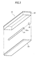
- Fig. 3 illustrates a configuration of essential parts of the transmission reading illumination portion 12 in which each member, including the frame 20, is elongated in the main-scan direction.
- an area that is capable of housing the transmission reading light guide 21 and the transmission reading light source 22 by fitting or the like is formed inside the frame 20, although the detailed structure and shape of the frame 20 is omitted from the drawing.
- the transmission reading light guide 21 is made of a transparent material, such as an acrylic resin or polycarbonate.
- a single transmission reading light guide 21 is disposed on the opposite side to the light receiving element 18 so that the transmission reading light guide 21 and the light receiving element 18 are above and below the bill S, respectively, on the optical axis of the rod-lens array 16.
- an end face on one side in the longitudinal direction thereof is formed as a light entering surface 21a which the light from the reflection reading light source 15 enters
- a bottom surface thereof is formed as a transmitted light emission surface 21b from which light that has propagated through the interior of the transmission reading light guide 21 is emitted
- a surface facing the transmitted light emission surface 21b is formed as a diffusing surface 21c.
- Light that is representatively shown in Fig. 1 is emitted toward the reading position O of the bill S from an orthogonal direction as shown by an arrow L 2 .
- the transmission reading light guide 21 in a state in which the transmission reading light guide 21 is mounted to the frame 20 as shown in Fig. 1 , with the surface on the bill S side serving as the transmitted light emission surface 21b, the transmission reading light guide 21 is exposed from the frame 20 and formed in a convex shape toward the bill S side so as to have a light collecting effect at the transmitted light emission surface 21b.
- the other surfaces than the light entering surface 21a and the transmitted light emission surface 21b are substantially formed as reflection surfaces. Light that is incident from the light entering surface 21a is reflected and diffused within the transmission reading light guide 21.
- the incident light propagates through the inside of the transmission reading light guide 21 while being subjected to total reflection by the reflection surface thereof, is emitted from the transmitted light emission surface 21b, and irradiated in a substantially uniform manner as a line of light in the main-scan direction toward the bill S.
- a transmission reading light source 22 is disposed on the light entering surface 21a. Although in the example illustrated in Fig. 3 the transmission reading light source 22 is disposed on an end face on one side of the transmission reading light guide 21, the transmission reading light source 22 may be provided on end faces on both sides of the transmission reading light guide 21.
- light emitting elements that comprise LEDs having emission wavelengths of the three colors of RGB and light emitting elements that comprise LEDs that emit IR and UV light are provided as the transmission reading light source 22.
- the RGB, IR and UV light emitting elements of the transmission reading light source 22 are successively activated to make them emit light to the bill S conveyed by the conveyor rollers 101A, 101B, 102A and 102B in the conveyance direction F at a predetermined conveyance speed.
- the light emitted from the transmission reading light source 22 propagates through the transmission reading light guide 21 and is uniformly irradiated as a line of light in the main-scan direction toward the reading position 0 on the surface of the bill S.
- the illumination light is transmitted through the bill S and then focused through the rod-lens array 16 to form an image on the photoelectric conversion element of the light receiving element 18.
- the transmitted light focused to form an image is converted into an electric signal (output signal) by the light receiving element 18, and the electric signal is processed by the signal processing portion.
- the operation of reading the bill S along one scan line in the main-scan direction is completed by reading all of the RGB, IR and UV transmitted light for one scan line as described above.
- the reading operation for one scan line is completed, the bill S is moved in the sub-scan direction, and a reading operation for the next one scan line is performed in a similar manner to the above described operation.
- the reading operation for one scan line is repeated while conveying the bill S in the conveyance direction F, thereby sequentially scanning the whole surface of the bill S to achieve reading of the image with the transmitted light.
- so-called "reflection light” that includes the relevant stray light and the like becomes a noise component in the output of the image sensor unit 10, and a difference between an output signal (signal component) when the bill S is present and the noise component produced by the stray light decreases, and if no countermeasure is taken, a problem may arise whereby the contrast becomes blurred and the accuracy of a read image decreases or the like.
- the image sensor unit 10 of the present invention has the image reading portion 11 and the transmission reading illumination portion 12, and is configured to combine the use of transmission type and reflection type reading.
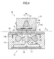
- a light blocking member 1 as light blocking means that blocks a part of light (L arrows in Fig. 4 ) that is irradiated to the transmission reading illumination portion 12 side from the image reading portion 11 is disposed between the reflection reading light guides 14 of the image reading portion 11 and the transmission reading light guide 21 of the transmission reading illumination portion 12.
- the light blocking member 1 is constituted by a light blocking cover or a light blocking sheet 1A that is disposed on the transmitted light emission surface 21b side of the transmission reading light guide 21 of the transmission reading illumination portion 12.
- the light blocking sheet 1A has a slit 2 that is formed in the main-scan direction.
- the slit 2 has a predetermined opening width W in the sub-scan direction.
- a part of the frame 13 of the image reading portion 11 can be formed as the light blocking sheet 1A, or the light blocking sheet 1A may be formed by providing a cover member that is a separate element as an accessory. Further, the light blocking sheet 1A may be a component to which a sheet member that is a separate element is affixed, or may be integrated with the cover glass 23. In each case, it is desirable that a surface on the image reading portion 11 side of the light blocking sheet 1A has a light absorption characteristic and the other surface on the transmission reading illumination portion 12 side thereof has a light reflection characteristic.
- the image sensor unit 10 by providing the light blocking sheet 1A as the light blocking member 1 between the reflection reading light guides 14 of the image reading portion 11 and the transmission reading light guide 21 of the transmission reading illumination portion 12, in particular, light beams that attempt to enter the transmission reading light guide 21 of the transmission reading illumination portion 12 from the image reading portion 11 side when performing a reading operation by means of the image reading portion 11 can be effectively blocked as shown in Fig. 4 .
- the light blocking sheet 1A is particularly effective, and a noise component in an output signal of the image sensor unit 10 that is ascribable to reflection light can be suppressed to a low level.
- Fig. 5A shows an output signal of the image sensor unit 10, more specifically, of the light receiving element 18 of the image reading portion 11, in a case where the light blocking member 1 is provided according to the present invention
- Fig. 5B shows, as a comparison example, an output signal of the image sensor unit 10 in a case where the light blocking member 1 is not provided.
- the light blocking member 1 in this example the light blocking sheet 1A, is not provided, in a state in which the bill S is not present on the conveyance path P and/or in a state in which reading is performed by the image reading portion 11 with respect to a watermark portion or the like, light that is emitted from the reflection reading light guides 14 of the image reading portion 11 becomes reflection light and reaches the transmission reading light guide 21 of the transmission reading illumination portion 12, and passes along the light transmission path (arrow L 2 ) as it is and is received by the light receiving element 18. Consequently, the output signal of the image sensor unit 10 increases significantly as shown in Fig. 5B .
- the background of the bill S in the image that is read is black, to enable edge detection of the bill S to be effectively performed.
- the contrast between the bill S and the background decreases, and if a countermeasure is not implemented, the detection accuracy or image quality decreases.
- the S/N ratio can be improved by effectively blocking such kind of reflection light, and thus a high quality image can be obtained.
- the output signal is made 0 in a state in which there is no bill S on the conveyance path P, in actuality it is difficult to make the output signal completely 0. According to the present invention, under such circumstances the influence of reflection light can be eliminated in a manner that is close to the ideal situation.
- the light blocking member 1 is constituted by a light blocking cover or a light blocking sheet 1B, and a slit 2' of the light blocking sheet 1B has a predetermined opening width W' in the sub-scan direction.
- a part of the frame 20 of the transmission reading illumination portion 12 can be formed as the light blocking sheet 1B, or the light blocking sheet 1B can be formed by providing a cover member that is a separate element as an accessory. Further, the light blocking sheet 1B may be a component to which a sheet member that is a separate element is affixed, or may be integrated with the cover glass 19. In each case, it is desirable that a surface on the image reading portion 11 side of the light blocking sheet 1B has a light absorption characteristic and the other surface on the transmission reading illumination portion 12 side thereof has a light reflection characteristic.
- the image sensor unit 10 by providing the light blocking sheet 1B as the light blocking member 1 between the reflection reading light guides 14 of the image reading portion 11 and the transmission reading light guide 21 of the transmission reading illumination portion 12, in particular, light beams (L arrows in Fig. 6 ) that attempt to enter the transmission reading light guide 21 of the transmission reading illumination portion 12 from the image reading portion 11 side when performing a reading operation by means of the image reading portion 11 can be effectively blocked. Accordingly, in this case also, reflection light can be prevented from reaching the transmission reading light guide 21 of the transmission reading illumination portion 12. Further, this configuration has the same actions and effects as the case of the light blocking sheet 1A.
- the light blocking sheet 1A and the light blocking sheet 1B are used individually as in the above described examples, they each have an excellent light blocking effect. It is also possible to use the light blocking sheet 1A and the light blocking sheet 1B in combination.
- FIG. 7 shows simulation results with respect to illumination depth characteristics of the transmission reading light source, in which the relation between the illumination depth (horizontal axis z in Fig. 7 ) and the relative illuminance (vertical axis in Fig. 7 ) is shown for a case in which the opening width W of the slit 2 of the light blocking sheet 1A (see Fig. 4 ) is varied. In this case, the opening width W is varied within the range of 1.5 mm to 10.0 mm.
- the term "illumination depth z (mm)" refers to, specifically, that a gap between the cover glass 23 of the transmission reading light source and the cover glass 19 of the reflection reading light source is 2 mm and a focal point (focus) is at a center part thereof.
- the light blocking sheet 1A exhibits an excellent function with respect to an action to prevent infiltration of reflection light, if the opening width W is narrowed excessively to around 1.5 mm, the illuminance is insufficient. Accordingly, it is preferable that the opening width W of the slit 2 of the light blocking sheet 1A is at least 2 mm or more.
- Fig. 8 shows, with respect to illumination depth characteristics of the reflection reading light source, simulation results for the relation between the illumination depth and the relative illuminance when the opening width W' of the slit 2' of the light blocking sheet 1B (see Fig. 6 ) is varied.
- the opening width W' is varied within the range of 5.0 mm to 10.0 mm.
- the light blocking sheet 1B also exhibits an excellent function with respect to preventing infiltration of reflection, if the opening width W' thereof is narrowed excessively to around 6.0 mm, the illuminance is insufficient. Accordingly, it is preferable that the opening width W' of the slit 2' of the light blocking sheet 1B is at least 6.5 mm or more.
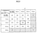
- Fig. 9 shows simulation results with respect to the relation between the opening widths W and W' of the slits 2 and 2' of the light blocking sheet 1A and the light blocking sheet 1B and reflection light.
- light amounts that are incident on the transmission reading light source are compared for a case where the opening width W of the slit 2 of the light blocking sheet 1A on the transmission reading illumination portion 12 side (transmission) is varied within the range of 1.5 mm to 3.0 mm and the opening width W' of the slit 2' of the light blocking sheet 1B on the image reading portion 11 side (reflection) is varied within the range of 6.0 mm to 7.5 mm.
- the amount of reflection light when neither of the light blocking sheet 1A and the light blocking sheet 1B is provided is taken as a reference value 1.00, and the respective proportions with respect to the reference value are shown.
- a range P in which the opening width W of the slit 2 of the light blocking sheet 1A is between 2.0 mm and 3.0 mm and the opening width W' of the slit 2' of the light blocking sheet 1B is between 6.5 mm and 7.5 mm is appropriate to effectively decrease the reflection light.
- a configuration in which the opening width W of the slit 2 of the light blocking sheet 1A is equal to 2.5 mm and the opening width W' of the slit 2' of the light blocking sheet 1B is equal to 7.0 mm is optimal.
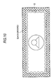
- Fig. 10 illustrates an example of an image that is obtained when reflection reading is performed with respect to the bill S in the image reading portion 11 of the image reading apparatus 100 that is provided with the image sensor unit 10 of the present invention.
- the background of the bill S or the like in a read image of the bill S or the like is black, to enable edge detection of the bill S to be effectively performed.
- the present invention by effectively blocking reflection light to reduce the influence thereof, the contrast between the bill S and the background is sharpened, and high detection accuracy can be ensured.
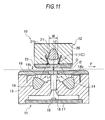
- Fig. 11 illustrates a different example in which the light blocking member 1 is disposed between the reflection reading light guides 14 of the image reading portion 11 and the transmission reading light guide 21 of the transmission reading illumination portion 12.
- the same symbols are used for the same or corresponding members.
- the light blocking member 1 is constituted by a light blocking sheet 1C that is disposed in an inclined manner so as to sandwich the transmission reading light guide 21 from both sides.
- the light blocking sheet 1C has a slit 2 formed in the main-scan direction, and the slit 2 has a predetermined opening width W in the sub-scan direction.
- Fig. 12 illustrates another different example of the light blocking member 1 that is disposed between the reflection reading light guides 14 of the image reading portion 11 and the transmission reading light guide 21 of the transmission reading illumination portion 12.
- the light blocking member 1 is constituted, for example, by a louver film 1D that is affixed to the cover glass 23.
- the louvers of the louver film 1D are formed so as to be oriented in the optical axis direction of the rod-lens array 16.
- the louver film 1D may be formed by alternately disposing light transmitting layers and light blocking layers, or may be a structure in which light blocking plates are provided in a blind shape.
- a polarizing filter on the side of the reflected light emission surfaces 14b of the reflection reading light guides 14 and the side of the transmitted light emission surface 21b of the transmission reading light guide 21, respectively. In this case, light beams that attempt to enter the transmission reading light guide 21 of the transmission reading illumination portion 12 from the image reading portion 11 side can be effectively blocked by making the polarizing angles orthogonal.
- Fig. 13 shows a further different example of the light blocking member 1 that is disposed between the reflection reading light guides 14 of the image reading portion 11 and the transmission reading light guide 21 of the transmission reading illumination portion 12.
- the light blocking member 1 is constituted, for example, by an optical filter 1E that is affixed to the cover glass 23 in the transmission reading illumination portion 12.
- an emission wavelength of the reflection reading light sources 15 of the image reading portion 11 and an emission wavelength of the transmission reading light source 22 of the transmission reading illumination portion 12 are different, and the optical filter 1E is configured to absorb light emitted from the reflection reading light sources 15, that is, the reflection reading light guides 14 of the image reading portion 11, and to transmit light emitted from the transmission reading light source 22, that is, the transmission reading light guide 21 of the transmission reading illumination portion 12.
- a combination of the emission wavelength of the reflection reading light sources 15 of the image reading portion 11 and the emission wavelength of the transmission reading light source 22 of the transmission reading illumination portion 12 for example, a combination may be adopted in which the reflection reading light sources 15 emit green light and the transmission reading light source 22 emits red light.
- the optical filter 1E that absorbs green light an operating environment can be constructed that transmits red light and absorbs green light.
- a wavelength that is absorbed by the optical filter 1E cannot be used as transmitted light.
- the wavelengths that can be used as transmitted light are IR and UV wavelengths.
- the reflection reading light sources 15 emit visible light and the transmission reading light source 22 emits infrared light. Therefore, by using the optical filter 1E that absorbs visible light, an operating environment can be constructed that transmits infrared light and absorbs visible light. In this case, by disposing the optical filter 1E on the transmission reading illumination portion 12 side, the optical filter 1E can be utilized as a black background member across the reading position 0 on the surface of the bill S, and hence an advantage is obtained such that edge detection of the bill S can be effectively performed.
- the width of the optical filter 1E in the sub-scan direction is equal to or greater than the diameter of a lens of the rod-lens array 16 and that the optical filter 1E contacts the white reference members 30 in the main-scan direction.
- white reference value refers to a reference value that is used when performing shading compensation, and is data for an image that has a uniform white density distribution.
- Shading compensation is performed to enhance the reproducibility of the tones of the bill S. More specifically, light amount adjustment is performed that makes an illumination light emitted to the bill S an appropriate amount, and gain adjustment is performed that makes an amplification factor with respect to the image signal output of the light receiving element 18 an appropriate amount.
- shading compensation is used when compensating for light amount unevenness of the reflection reading light sources 15, the transmission reading light source 22, and the rod-lens array 16, and for sensitivity unevenness of the light receiving element 18 in pixel units.
- Fig. 16 illustrates another different example of the light blocking member 1 that is disposed between the reflection reading light guides 14 of the image reading portion 11 and the transmission reading light guide 21 of the transmission reading illumination portion 12.
- the light blocking member 1 is constituted by a germanium layer 1F that is affixed to, for example, the cover glass 23 in the transmission reading illumination portion 12.
- an emission wavelength of the respective reflection reading light sources 15 of the image reading portion 11 and an emission wavelength of the transmission reading light source 22 of the transmission reading illumination portion 12 are different, and the germanium layer 1F is configured to reflect light emitted from the reflection reading light sources 15, that is, the reflection reading light guides 14 of the image reading portion 11, and transmit light emitted from the transmission reading light source 22, that is, the transmission reading light guide 21 of the transmission reading illumination portion 12.
- the light blocking member 1 is constituted by the germanium layer 1F, visible light from the reflection reading light sources 15 is reflected, and infrared light from the transmission reading light source 22 is transmitted.
- the IR light wavelength can be used as the wavelength of the transmitted light. Therefore, by using the cover glass 23 to which the germanium layer 1F is affixed in combination with the white reference members 30, the same effects can be achieved as in the example using the optical filter 1E that is described above. The same effects also can be achieved when the cover glass 23 is made of germanium.
- the light blocking member 1 is configured as a separate element (including a case of being integrated with the frame 20, the cover glass 19, and the cover glass 23).
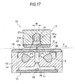
- an equivalent configuration can be achieved by means of the transmission reading light guide 21 of the transmission reading illumination portion 12. That is, a width w along the sub-scan direction of the transmitted light emission surface 21b of the transmission reading light guide 21 is narrower than other areas of the transmission reading light guide 21.
- the width w of the transmitted light emission surface 21b of the transmission reading light guide 21 narrow, it is extremely difficult for light beams (L arrows in Fig. 17 ) that attempt to enter the transmission reading light guide 21 of the transmission reading illumination portion 12 from the image reading portion 11 side to be incident on the transmission reading light guide 21. More specifically, light that attempts to enter the transmission reading light guide 21 of the transmission reading illumination portion 12 can be substantially blocked.
- side surfaces 21c of the transmission reading light guide 21 are set at an angle so as to directly reflect light beams (L arrows in Fig. 17 ) that attempt to enter the transmission reading light guide 21 of the transmission reading illumination portion 12 from the image reading portion 11 side.
- the side surfaces 21c of the transmission reading light guide 21 can be made to function substantially as the light blocking member 1.
- An image sensor unit performs image reading by reflected light and image reading by transmitted light with respect to a bill, and includes a reflection reading light guide that emits light from a reflection reading light source toward the bill, a transmission reading light guide that emits light from a transmission reading light source toward the bill, an imaging element that focuses light from the bill, and a light receiving element that receives light that is collected by the imaging element.
- the transmission reading light source and the transmission reading light guide are disposed on the opposite side of a conveyance path through which the bill can pass, for the reflection reading light source and the reflection reading light guide, and a light blocking member that blocks a part of the light from the reflection reading light guide is disposed between the reflection reading light guide and the transmission reading light guide.
Landscapes
- Engineering & Computer Science (AREA)
- Multimedia (AREA)
- Signal Processing (AREA)
- Health & Medical Sciences (AREA)
- General Health & Medical Sciences (AREA)
- Toxicology (AREA)
- Physics & Mathematics (AREA)
- General Physics & Mathematics (AREA)
- Optics & Photonics (AREA)
- Facsimile Scanning Arrangements (AREA)
- Image Input (AREA)
- Facsimile Heads (AREA)
- Inspection Of Paper Currency And Valuable Securities (AREA)
- Light Sources And Details Of Projection-Printing Devices (AREA)
Applications Claiming Priority (2)
| Application Number | Priority Date | Filing Date | Title |
|---|---|---|---|
| JP2011174375 | 2011-08-09 | ||
| JP2012161534A JP5536150B2 (ja) | 2011-08-09 | 2012-07-20 | イメージセンサユニット及び画像読取装置 |
Publications (1)
| Publication Number | Publication Date |
|---|---|
| EP2557769A1 true EP2557769A1 (de) | 2013-02-13 |
Family
ID=46690398
Family Applications (1)
| Application Number | Title | Priority Date | Filing Date |
|---|---|---|---|
| EP12179608A Withdrawn EP2557769A1 (de) | 2011-08-09 | 2012-08-08 | Bildsensoreinheit und Bildlesevorrichtung |
Country Status (5)
| Country | Link |
|---|---|
| US (1) | US8797609B2 (de) |
| EP (1) | EP2557769A1 (de) |
| JP (1) | JP5536150B2 (de) |
| KR (1) | KR101395985B1 (de) |
| CN (2) | CN102930631B (de) |
Cited By (1)
| Publication number | Priority date | Publication date | Assignee | Title |
|---|---|---|---|---|
| EP3101630A1 (de) * | 2015-06-03 | 2016-12-07 | Hitachi-Omron Terminal Solutions, Corp. | Vorrichtung zur papierblatthandhabung |
Families Citing this family (41)
| Publication number | Priority date | Publication date | Assignee | Title |
|---|---|---|---|---|
| EP2521346A4 (de) | 2009-12-28 | 2015-07-29 | Canon Components Kk | Kontaktbildsensoreinheit und bildlesevorrichtung damit |
| JP5139507B2 (ja) | 2010-12-10 | 2013-02-06 | キヤノン・コンポーネンツ株式会社 | イメージセンサユニット、及び、画像読取装置 |
| JP5204207B2 (ja) | 2010-12-17 | 2013-06-05 | キヤノン・コンポーネンツ株式会社 | イメージセンサユニットおよびそれを用いた画像読取装置 |
| JP5244952B2 (ja) | 2010-12-21 | 2013-07-24 | キヤノン・コンポーネンツ株式会社 | イメージセンサユニット、及び、画像読取装置 |
| JP5384471B2 (ja) | 2010-12-28 | 2014-01-08 | キヤノン・コンポーネンツ株式会社 | イメージセンサユニット、及び、画像読取装置 |
| JP5400188B2 (ja) | 2011-05-11 | 2014-01-29 | キヤノン・コンポーネンツ株式会社 | イメージセンサユニットおよびそれを用いた画像読取装置、画像形成装置 |
| JP5518953B2 (ja) | 2011-08-09 | 2014-06-11 | キヤノン・コンポーネンツ株式会社 | イメージセンサユニットおよび画像読取装置 |
| JP5384707B2 (ja) | 2011-08-09 | 2014-01-08 | キヤノン・コンポーネンツ株式会社 | イメージセンサユニット及びこれを用いた画像読取装置 |
| JP5536150B2 (ja) * | 2011-08-09 | 2014-07-02 | キヤノン・コンポーネンツ株式会社 | イメージセンサユニット及び画像読取装置 |
| WO2013022060A1 (ja) * | 2011-08-09 | 2013-02-14 | キヤノン・コンポーネンツ株式会社 | イメージセンサユニット及びこれを用いた画像読取装置 |
| JP5959001B2 (ja) * | 2012-07-20 | 2016-08-02 | 株式会社小森コーポレーション | シート状物の検査装置 |
| JP5856994B2 (ja) * | 2013-03-28 | 2016-02-10 | 京セラドキュメントソリューションズ株式会社 | 照明装置、およびこれを備えた画像読取装置、画像形成装置 |
| JP5817779B2 (ja) | 2013-04-23 | 2015-11-18 | コニカミノルタ株式会社 | 導光体、照明装置、および画像読取装置 |
| CN103414838B (zh) | 2013-06-20 | 2015-12-23 | 威海华菱光电股份有限公司 | 图像扫描装置及其控制方法 |
| WO2015141461A1 (ja) * | 2014-03-17 | 2015-09-24 | 三菱電機株式会社 | 照明装置および画像読取装置 |
| JP6060937B2 (ja) * | 2014-06-06 | 2017-01-18 | 三菱電機株式会社 | 画像読取装置 |
| JP6081407B2 (ja) * | 2014-06-12 | 2017-02-15 | キヤノン・コンポーネンツ株式会社 | イメージセンサユニット、読取装置、画像形成装置および回路基板 |
| TWI656085B (zh) * | 2015-01-16 | 2019-04-11 | 虹光精密工業股份有限公司 | 列印裝置 |
| CN105872279B (zh) * | 2015-02-10 | 2018-11-09 | 佳能元件股份有限公司 | 图像传感器单元、纸张识别装置、图像读取以及形成装置 |
| US10382647B2 (en) * | 2015-06-04 | 2019-08-13 | Canon Components, Inc. | Image sensor unit, paper sheet distinguishing apparatus, and image reading apparatus |
| JP1553846S (de) * | 2015-06-18 | 2016-07-11 | ||
| JP1553848S (de) * | 2015-06-18 | 2016-07-11 | ||
| JP1553414S (de) * | 2015-06-18 | 2016-07-11 | ||
| JP1553417S (de) * | 2015-06-18 | 2016-07-11 | ||
| JP1553845S (de) * | 2015-06-18 | 2016-07-11 | ||
| JP1553847S (de) * | 2015-06-18 | 2016-07-11 | ||
| JP1553412S (de) * | 2015-06-18 | 2016-07-11 | ||
| JP6579863B2 (ja) | 2015-08-27 | 2019-09-25 | キヤノン・コンポーネンツ株式会社 | 読取装置および透過光源ユニット |
| CN106056749A (zh) * | 2016-07-15 | 2016-10-26 | 深圳怡化电脑股份有限公司 | 一种纸币检测装置 |
| WO2018173210A1 (ja) * | 2017-03-23 | 2018-09-27 | 株式会社ヴィーネックス | 紫外線蛍光色検出装置及び紫外線蛍光色検出方法 |
| JP6395988B1 (ja) * | 2017-06-28 | 2018-09-26 | 三菱電機株式会社 | 導光体及び画像読取装置 |
| CN111557050A (zh) * | 2018-01-15 | 2020-08-18 | 索尼公司 | 生物体信息获取装置、生物体信息获取方法和可穿戴装置 |
| US10899566B2 (en) | 2018-04-20 | 2021-01-26 | Crane Payment Innovations, Inc. | String detection system |
| JP7185439B2 (ja) * | 2018-08-01 | 2022-12-07 | 株式会社ヴィーネックス | 光ラインセンサユニット |
| WO2020150908A1 (en) * | 2019-01-22 | 2020-07-30 | SZ DJI Technology Co., Ltd. | Image sensor and fabrication method thereof |
| DE112020004764T5 (de) * | 2019-10-04 | 2022-06-30 | Mitsubishi Electric Corporation | Bildsensoreinheit und Verfahren zur Produktion einer Bildsensoreinheit |
| TWI749814B (zh) * | 2020-10-16 | 2021-12-11 | 虹光精密工業股份有限公司 | 多模式掃描裝置 |
| TWI768509B (zh) * | 2020-10-16 | 2022-06-21 | 虹光精密工業股份有限公司 | 執行不可見光反射的多模式掃描裝置 |
| TWI778430B (zh) * | 2020-10-16 | 2022-09-21 | 虹光精密工業股份有限公司 | 執行平台式掃描的多模式掃描裝置 |
| CN114429690B (zh) * | 2022-03-15 | 2025-01-14 | 温州铂芯电子科技有限公司 | 一种多光谱的纸币检验装置及点钞机 |
| WO2025126870A1 (ja) * | 2023-12-15 | 2025-06-19 | 三菱電機株式会社 | 画像読取装置 |
Citations (12)
| Publication number | Priority date | Publication date | Assignee | Title |
|---|---|---|---|---|
| EP0252709A2 (de) * | 1986-07-07 | 1988-01-13 | Canon Kabushiki Kaisha | Projektionsapparat und Bildleseapparat, fähig zum Lesen eines projizierten Bildes |
| FR2655799A1 (fr) * | 1989-12-11 | 1991-06-14 | Edery Aime | Dispositif d'analyse de documents. |
| US5119232A (en) * | 1990-12-17 | 1992-06-02 | Hughes Aircraft Company | Infrared-transmissive optical window |
| EP0557891A1 (de) * | 1992-02-28 | 1993-09-01 | Kabushiki Kaisha Toshiba | Kontaktbildsensor zur Erzeugung von elektrischen Signalen entsprechend einem Bild auf einem Dokument |
| US5673122A (en) * | 1994-02-14 | 1997-09-30 | Fuji Photo Film Co., Ltd. | Image reading apparatus including slit member disposed between film original and reading lens |
| EP1049055A2 (de) * | 1999-04-26 | 2000-11-02 | Glory Ltd. | Bilderfassungsgerät mit Mehrwellenlängen-Lichtquellen und Verfahren zur Kontrolle desselben |
| US7042598B2 (en) * | 2001-03-15 | 2006-05-09 | Hewlett-Packard Development Company, L.P. | Variable reflectance cover |
| US20060268346A1 (en) * | 2005-05-27 | 2006-11-30 | Visioneer, Inc. A Wholly Owned Subsidiary Of Soque Holdings, Ltd. | Method and apparatus for elimination of ghosting or reverse side reflection in a scanned document |
| JP2007194797A (ja) | 2006-01-18 | 2007-08-02 | Mitsubishi Electric Corp | 読取装置 |
| EP1835469A2 (de) * | 2006-03-15 | 2007-09-19 | Mitsubishi Denki Kabushiki Kaisha | Bildlesegerät |
| US20090027743A1 (en) * | 2007-07-24 | 2009-01-29 | Samsung Electronics Co., Ltd. | Image reading device and image forming apparatus having the same |
| EP2134071A2 (de) * | 2008-06-11 | 2009-12-16 | Mitsubishi Electric Corporation | Bildlesevorrichtung |
Family Cites Families (55)
| Publication number | Priority date | Publication date | Assignee | Title |
|---|---|---|---|---|
| JP2679014B2 (ja) * | 1986-03-19 | 1997-11-19 | オリンパス光学工業株式会社 | 電子内視鏡装置 |
| JPH08223417A (ja) | 1995-02-10 | 1996-08-30 | Fuji Xerox Co Ltd | 画像読み取り装置 |
| US5910816A (en) * | 1995-06-07 | 1999-06-08 | Stryker Corporation | Imaging system with independent processing of visible an infrared light energy |
| JPH0974465A (ja) | 1995-07-04 | 1997-03-18 | Ricoh Co Ltd | 原稿読取装置 |
| JP3666969B2 (ja) | 1996-02-08 | 2005-06-29 | キヤノン株式会社 | 画像読取装置及び光源ユニット |
| US6191873B1 (en) | 1996-11-25 | 2001-02-20 | Canon Kabushiki Kaisha | Image reading device, image reading apparatus, and method therefor |
| JPH10285330A (ja) | 1997-04-11 | 1998-10-23 | Rohm Co Ltd | 密着型イメージセンサ |
| JP3999315B2 (ja) * | 1997-08-29 | 2007-10-31 | ローム株式会社 | イメージセンサ基板、およびこれを用いたイメージセンサ |
| US7683926B2 (en) * | 1999-02-25 | 2010-03-23 | Visionsense Ltd. | Optical device |
| DE19923557B4 (de) * | 1999-05-21 | 2006-07-13 | Daimlerchrysler Ag | Gebauter luftspaltisolierter Abgaskrümmer einer Abgasanlage eines Kraftfahrzeuges und ein Verfahren zu dessen Herstellung |
| JP2001005122A (ja) | 1999-06-18 | 2001-01-12 | Canon Inc | 照明装置及びそれを備えるイメージセンサ、原稿読取装置、情報処理システム |
| US6635011B1 (en) * | 2000-01-14 | 2003-10-21 | Pentax Corporation | Electronic endoscope system |
| US6527440B1 (en) * | 2000-08-31 | 2003-03-04 | Siemens Westinghouse Power Corporation | Optical power generator system condition status indicator and methods of indicating same |
| JP2003037717A (ja) | 2001-07-23 | 2003-02-07 | Ricoh Co Ltd | 画像読み取り装置及び画像形成装置 |
| JP2003046726A (ja) | 2001-07-30 | 2003-02-14 | Kanegafuchi Chem Ind Co Ltd | 紙葉類の印刷パターン読取装置 |
| JP2003281913A (ja) | 2002-03-22 | 2003-10-03 | Nippon Sheet Glass Co Ltd | 照明装置および画像読み取り装置 |
| JP2004146870A (ja) | 2002-10-21 | 2004-05-20 | Nippon Sheet Glass Co Ltd | ライン照明装置およびこのライン照明装置を組み込んだ画像読取装置 |
| JP2004326624A (ja) | 2003-04-25 | 2004-11-18 | Aruze Corp | 識別センサ |
| JP3885088B2 (ja) | 2003-11-27 | 2007-02-21 | キヤノン・コンポーネンツ株式会社 | イメージセンサーユニット及び画像読取装置 |
| JP2005223424A (ja) | 2004-02-03 | 2005-08-18 | Canon Components Inc | 密着型イメージセンサユニット及びその実装方法 |
| JP4575720B2 (ja) * | 2004-07-23 | 2010-11-04 | Hoya株式会社 | 電子内視鏡システム |
| US7365268B2 (en) * | 2004-12-30 | 2008-04-29 | Edsal Manufacturing Co., Inc. | Storage receptacle |
| JP2006311232A (ja) | 2005-04-28 | 2006-11-09 | Seiko Epson Corp | 撮像ユニット、その製造方法及び画像形成装置 |
| US8199377B2 (en) * | 2005-06-07 | 2012-06-12 | Nippon Sheet Glass Company, Limited | Image sensor and image reading device |
| WO2006137263A1 (ja) | 2005-06-21 | 2006-12-28 | Nippon Sheet Glass Company, Limited | イメージセンサ、画像読取装置及びイメージセンサの製造方法 |
| JP4123266B2 (ja) | 2005-10-24 | 2008-07-23 | 三菱電機株式会社 | イメージセンサ |
| JP4320656B2 (ja) * | 2005-12-13 | 2009-08-26 | 三菱電機株式会社 | 画像読取装置 |
| JP4578528B2 (ja) | 2006-01-05 | 2010-11-10 | 日本板硝子株式会社 | ライン照明装置、密着型イメージセンサ及び画像読取装置 |
| US20070285740A1 (en) | 2006-05-02 | 2007-12-13 | Rohm Co., Ltd. | Image sensor module |
| JP2008042425A (ja) | 2006-08-04 | 2008-02-21 | Rohm Co Ltd | イメージセンサモジュール |
| JP2007300536A (ja) | 2006-05-02 | 2007-11-15 | Rohm Co Ltd | 画像読取装置、およびその製造方法 |
| JP4222384B2 (ja) * | 2006-05-25 | 2009-02-12 | セイコーエプソン株式会社 | 画像読取装置および複合機 |
| JP4424336B2 (ja) * | 2006-07-20 | 2010-03-03 | 三菱電機株式会社 | イメージセンサ |
| JPWO2008013234A1 (ja) | 2006-07-27 | 2009-12-17 | キヤノン・コンポーネンツ株式会社 | ライン状照明装置、イメージセンサ及びそれを用いた画像読取装置 |
| JP5116273B2 (ja) * | 2006-09-19 | 2013-01-09 | 株式会社リコー | 光走査装置、遮光材、フレア光の遮蔽方法及び画像形成装置 |
| JP4785690B2 (ja) | 2006-09-19 | 2011-10-05 | キヤノン株式会社 | 画像読取装置及び画像読取装置の制御方法 |
| JP5030530B2 (ja) | 2006-10-30 | 2012-09-19 | 株式会社ヴィーネックス | 発光素子アレイおよび紙葉類の認識装置 |
| JP2008124788A (ja) | 2006-11-13 | 2008-05-29 | Brother Ind Ltd | 画像読取装置 |
| JP2009086488A (ja) | 2007-10-02 | 2009-04-23 | Rohm Co Ltd | 線状光源装置、およびイメージセンサモジュール |
| US8442091B2 (en) * | 2007-10-25 | 2013-05-14 | The Board Of Trustees Of The University Of Illinois | Microchannel laser having microplasma gain media |
| US7796310B2 (en) * | 2007-10-31 | 2010-09-14 | Canon Denshi Kabushiki Kaisha | Image reading apparatus and control method therefor, as well as storage medium |
| JP5233625B2 (ja) | 2008-12-04 | 2013-07-10 | 株式会社リコー | 画像読取装置および画像形成装置 |
| EP2246825B1 (de) | 2009-04-28 | 2014-10-08 | Banqit AB | Verfahren für eine Banknotendetektionsvorrichtung und eine Banknotendetektionsvorrichtung |
| JP4868062B2 (ja) | 2009-12-10 | 2012-02-01 | 三菱電機株式会社 | 照明装置及びそれを用いた画像読取装置 |
| EP2521346A4 (de) | 2009-12-28 | 2015-07-29 | Canon Components Kk | Kontaktbildsensoreinheit und bildlesevorrichtung damit |
| JP5548017B2 (ja) * | 2010-04-21 | 2014-07-16 | 株式会社Pfu | 画像読取装置 |
| JP5587025B2 (ja) * | 2010-04-28 | 2014-09-10 | パナソニック株式会社 | 導光体並びにこれを備えた照明装置及び原稿読取装置 |
| US20110286054A1 (en) * | 2010-05-19 | 2011-11-24 | Toshiba Tec Kabushiki Kaisha | Reading head |
| JP5204207B2 (ja) | 2010-12-17 | 2013-06-05 | キヤノン・コンポーネンツ株式会社 | イメージセンサユニットおよびそれを用いた画像読取装置 |
| JP5244952B2 (ja) | 2010-12-21 | 2013-07-24 | キヤノン・コンポーネンツ株式会社 | イメージセンサユニット、及び、画像読取装置 |
| JP5384471B2 (ja) * | 2010-12-28 | 2014-01-08 | キヤノン・コンポーネンツ株式会社 | イメージセンサユニット、及び、画像読取装置 |
| JP5400188B2 (ja) | 2011-05-11 | 2014-01-29 | キヤノン・コンポーネンツ株式会社 | イメージセンサユニットおよびそれを用いた画像読取装置、画像形成装置 |
| JP5518953B2 (ja) | 2011-08-09 | 2014-06-11 | キヤノン・コンポーネンツ株式会社 | イメージセンサユニットおよび画像読取装置 |
| JP5384707B2 (ja) | 2011-08-09 | 2014-01-08 | キヤノン・コンポーネンツ株式会社 | イメージセンサユニット及びこれを用いた画像読取装置 |
| JP5536150B2 (ja) * | 2011-08-09 | 2014-07-02 | キヤノン・コンポーネンツ株式会社 | イメージセンサユニット及び画像読取装置 |
-
2012
- 2012-07-20 JP JP2012161534A patent/JP5536150B2/ja not_active Expired - Fee Related
- 2012-08-08 KR KR1020120086906A patent/KR101395985B1/ko not_active Expired - Fee Related
- 2012-08-08 EP EP12179608A patent/EP2557769A1/de not_active Withdrawn
- 2012-08-09 US US13/570,645 patent/US8797609B2/en not_active Expired - Fee Related
- 2012-08-09 CN CN201210283329.4A patent/CN102930631B/zh not_active Expired - Fee Related
- 2012-08-09 CN CN201220395045XU patent/CN202870958U/zh not_active Expired - Fee Related
Patent Citations (12)
| Publication number | Priority date | Publication date | Assignee | Title |
|---|---|---|---|---|
| EP0252709A2 (de) * | 1986-07-07 | 1988-01-13 | Canon Kabushiki Kaisha | Projektionsapparat und Bildleseapparat, fähig zum Lesen eines projizierten Bildes |
| FR2655799A1 (fr) * | 1989-12-11 | 1991-06-14 | Edery Aime | Dispositif d'analyse de documents. |
| US5119232A (en) * | 1990-12-17 | 1992-06-02 | Hughes Aircraft Company | Infrared-transmissive optical window |
| EP0557891A1 (de) * | 1992-02-28 | 1993-09-01 | Kabushiki Kaisha Toshiba | Kontaktbildsensor zur Erzeugung von elektrischen Signalen entsprechend einem Bild auf einem Dokument |
| US5673122A (en) * | 1994-02-14 | 1997-09-30 | Fuji Photo Film Co., Ltd. | Image reading apparatus including slit member disposed between film original and reading lens |
| EP1049055A2 (de) * | 1999-04-26 | 2000-11-02 | Glory Ltd. | Bilderfassungsgerät mit Mehrwellenlängen-Lichtquellen und Verfahren zur Kontrolle desselben |
| US7042598B2 (en) * | 2001-03-15 | 2006-05-09 | Hewlett-Packard Development Company, L.P. | Variable reflectance cover |
| US20060268346A1 (en) * | 2005-05-27 | 2006-11-30 | Visioneer, Inc. A Wholly Owned Subsidiary Of Soque Holdings, Ltd. | Method and apparatus for elimination of ghosting or reverse side reflection in a scanned document |
| JP2007194797A (ja) | 2006-01-18 | 2007-08-02 | Mitsubishi Electric Corp | 読取装置 |
| EP1835469A2 (de) * | 2006-03-15 | 2007-09-19 | Mitsubishi Denki Kabushiki Kaisha | Bildlesegerät |
| US20090027743A1 (en) * | 2007-07-24 | 2009-01-29 | Samsung Electronics Co., Ltd. | Image reading device and image forming apparatus having the same |
| EP2134071A2 (de) * | 2008-06-11 | 2009-12-16 | Mitsubishi Electric Corporation | Bildlesevorrichtung |
Cited By (2)
| Publication number | Priority date | Publication date | Assignee | Title |
|---|---|---|---|---|
| EP3101630A1 (de) * | 2015-06-03 | 2016-12-07 | Hitachi-Omron Terminal Solutions, Corp. | Vorrichtung zur papierblatthandhabung |
| US9704326B2 (en) | 2015-06-03 | 2017-07-11 | Hitachi-Omron Terminal Solutions, Corp. | Paper sheet handling apparatus |
Also Published As
| Publication number | Publication date |
|---|---|
| US8797609B2 (en) | 2014-08-05 |
| JP5536150B2 (ja) | 2014-07-02 |
| JP2013055646A (ja) | 2013-03-21 |
| CN102930631A (zh) | 2013-02-13 |
| KR20130018618A (ko) | 2013-02-25 |
| CN102930631B (zh) | 2015-03-18 |
| CN202870958U (zh) | 2013-04-10 |
| US20130038913A1 (en) | 2013-02-14 |
| KR101395985B1 (ko) | 2014-05-16 |
Similar Documents
| Publication | Publication Date | Title |
|---|---|---|
| US8797609B2 (en) | Image sensor unit and image reading apparatus | |
| US9094562B2 (en) | Image sensor unit and image reading apparatus using the image sensor unit | |
| US8681396B2 (en) | Image sensor unit and image reading apparatus using the same | |
| EP2584543A2 (de) | Bildsensoreinheit und Bildlesevorrichtung | |
| US20160006898A1 (en) | Image sensor unit, paper sheet distinguishing apparatus, image reading apparatus, and image forming apparatus | |
| JPH06342131A (ja) | レンズアレイ及びそれを用いた密着型イメージセンサー | |
| EP2495948B1 (de) | Beleuchtungsvorrichtung, bilderfassungsvorrichtung mit dieser beleuchtungsvorrichtung sowie bilderzeugungsvorrichtung mit dieser beleuchtungsvorrichtung | |
| US9838559B2 (en) | Illumination apparatus, image sensor unit and image reading apparatus | |
| US9854118B2 (en) | Image reading apparatus | |
| US20060187500A1 (en) | Image reading device, image forming apparatus, and image reading method | |
| US10574852B2 (en) | Imaging optical mechanism, reading module, and image reading apparatus | |
| US20060197822A1 (en) | Illumination device, image reading device, and image forming apparatus | |
| TW200526011A (en) | Image sensor, and image reader | |
| US12346038B2 (en) | Reading apparatus, image forming apparatus, and reading method | |
| JP7040300B2 (ja) | 結像光学機構、読取モジュールおよび画像読取装置 | |
| US20180131832A1 (en) | Image sensor unit, paper sheet distinguishing apparatus, image reading apparatus, and image forming apparatus | |
| US11729332B2 (en) | Light source unit in which surface opposite to light emitting element of light guide is not covered and medium side surface of reflector protrudes from light guide | |
| JP6630618B2 (ja) | イメージセンサユニット、紙葉類識別装置、画像読取装置、画像形成装置 | |
| JP2012239031A (ja) | イメージセンサユニットおよびそれを用いた画像読取装置 | |
| JP2018026622A (ja) | イメージセンサユニット、紙葉類識別装置、画像読取装置 | |
| JP2017046247A (ja) | イメージセンサユニット、紙葉類識別装置、画像読取装置、画像形成装置 |
Legal Events
| Date | Code | Title | Description |
|---|---|---|---|
| PUAI | Public reference made under article 153(3) epc to a published international application that has entered the european phase |
Free format text: ORIGINAL CODE: 0009012 |
|
| AK | Designated contracting states |
Kind code of ref document: A1 Designated state(s): AL AT BE BG CH CY CZ DE DK EE ES FI FR GB GR HR HU IE IS IT LI LT LU LV MC MK MT NL NO PL PT RO RS SE SI SK SM TR |
|
| AX | Request for extension of the european patent |
Extension state: BA ME |
|
| 17P | Request for examination filed |
Effective date: 20130806 |
|
| RBV | Designated contracting states (corrected) |
Designated state(s): AL AT BE BG CH CY CZ DE DK EE ES FI FR GB GR HR HU IE IS IT LI LT LU LV MC MK MT NL NO PL PT RO RS SE SI SK SM TR |
|
| 17Q | First examination report despatched |
Effective date: 20140314 |
|
| STAA | Information on the status of an ep patent application or granted ep patent |
Free format text: STATUS: THE APPLICATION IS DEEMED TO BE WITHDRAWN |
|
| 18D | Application deemed to be withdrawn |
Effective date: 20170301 |