EP2559942A1 - Tête de chambre de combustion d'une turbine à gaz dotée d'un refroidissement et d'un amortissement - Google Patents
Tête de chambre de combustion d'une turbine à gaz dotée d'un refroidissement et d'un amortissement Download PDFInfo
- Publication number
- EP2559942A1 EP2559942A1 EP11006812A EP11006812A EP2559942A1 EP 2559942 A1 EP2559942 A1 EP 2559942A1 EP 11006812 A EP11006812 A EP 11006812A EP 11006812 A EP11006812 A EP 11006812A EP 2559942 A1 EP2559942 A1 EP 2559942A1
- Authority
- EP
- European Patent Office
- Prior art keywords
- combustion chamber
- wall
- cooling air
- damping
- head
- Prior art date
- Legal status (The legal status is an assumption and is not a legal conclusion. Google has not performed a legal analysis and makes no representation as to the accuracy of the status listed.)
- Withdrawn
Links
Images






Classifications
-
- F—MECHANICAL ENGINEERING; LIGHTING; HEATING; WEAPONS; BLASTING
- F23—COMBUSTION APPARATUS; COMBUSTION PROCESSES
- F23R—GENERATING COMBUSTION PRODUCTS OF HIGH PRESSURE OR HIGH VELOCITY, e.g. GAS-TURBINE COMBUSTION CHAMBERS
- F23R3/00—Continuous combustion chambers using liquid or gaseous fuel
- F23R3/02—Continuous combustion chambers using liquid or gaseous fuel characterised by the air-flow or gas-flow configuration
- F23R3/04—Air inlet arrangements
- F23R3/10—Air inlet arrangements for primary air
-
- F—MECHANICAL ENGINEERING; LIGHTING; HEATING; WEAPONS; BLASTING
- F23—COMBUSTION APPARATUS; COMBUSTION PROCESSES
- F23M—CASINGS, LININGS, WALLS OR DOORS SPECIALLY ADAPTED FOR COMBUSTION CHAMBERS, e.g. FIREBRIDGES; DEVICES FOR DEFLECTING AIR, FLAMES OR COMBUSTION PRODUCTS IN COMBUSTION CHAMBERS; SAFETY ARRANGEMENTS SPECIALLY ADAPTED FOR COMBUSTION APPARATUS; DETAILS OF COMBUSTION CHAMBERS, NOT OTHERWISE PROVIDED FOR
- F23M20/00—Details of combustion chambers, not otherwise provided for, e.g. means for storing heat from flames
- F23M20/005—Noise absorbing means
-
- F—MECHANICAL ENGINEERING; LIGHTING; HEATING; WEAPONS; BLASTING
- F23—COMBUSTION APPARATUS; COMBUSTION PROCESSES
- F23R—GENERATING COMBUSTION PRODUCTS OF HIGH PRESSURE OR HIGH VELOCITY, e.g. GAS-TURBINE COMBUSTION CHAMBERS
- F23R2900/00—Special features of, or arrangements for continuous combustion chambers; Combustion processes therefor
- F23R2900/00014—Reducing thermo-acoustic vibrations by passive means, e.g. by Helmholtz resonators
-
- F—MECHANICAL ENGINEERING; LIGHTING; HEATING; WEAPONS; BLASTING
- F23—COMBUSTION APPARATUS; COMBUSTION PROCESSES
- F23R—GENERATING COMBUSTION PRODUCTS OF HIGH PRESSURE OR HIGH VELOCITY, e.g. GAS-TURBINE COMBUSTION CHAMBERS
- F23R2900/00—Special features of, or arrangements for continuous combustion chambers; Combustion processes therefor
- F23R2900/00017—Assembling combustion chamber liners or subparts
-
- F—MECHANICAL ENGINEERING; LIGHTING; HEATING; WEAPONS; BLASTING
- F23—COMBUSTION APPARATUS; COMBUSTION PROCESSES
- F23R—GENERATING COMBUSTION PRODUCTS OF HIGH PRESSURE OR HIGH VELOCITY, e.g. GAS-TURBINE COMBUSTION CHAMBERS
- F23R2900/00—Special features of, or arrangements for continuous combustion chambers; Combustion processes therefor
- F23R2900/03042—Film cooled combustion chamber walls or domes
-
- F—MECHANICAL ENGINEERING; LIGHTING; HEATING; WEAPONS; BLASTING
- F23—COMBUSTION APPARATUS; COMBUSTION PROCESSES
- F23R—GENERATING COMBUSTION PRODUCTS OF HIGH PRESSURE OR HIGH VELOCITY, e.g. GAS-TURBINE COMBUSTION CHAMBERS
- F23R2900/00—Special features of, or arrangements for continuous combustion chambers; Combustion processes therefor
- F23R2900/03043—Convection cooled combustion chamber walls with means for guiding the cooling air flow
-
- F—MECHANICAL ENGINEERING; LIGHTING; HEATING; WEAPONS; BLASTING
- F23—COMBUSTION APPARATUS; COMBUSTION PROCESSES
- F23R—GENERATING COMBUSTION PRODUCTS OF HIGH PRESSURE OR HIGH VELOCITY, e.g. GAS-TURBINE COMBUSTION CHAMBERS
- F23R2900/00—Special features of, or arrangements for continuous combustion chambers; Combustion processes therefor
- F23R2900/03045—Convection cooled combustion chamber walls provided with turbolators or means for creating turbulences to increase cooling
Definitions
- the invention relates to a combustion chamber head of a gas turbine.
- the combustion chamber includes a substantially annular outer combustion chamber wall and a substantially annular inner combustion chamber wall.
- the two combustion chamber walls are connected to the combustion chamber head.
- the combustion chamber head has at least one opening through which at least one burner can be pushed through and thus connected to the combustion chamber.
- At least one heat shield protects the combustion head from the hot combustion gases.
- the combustion chamber head may consist of one or more segments.
- the structure of a conventional heat shield for a combustion chamber head is in DE 44 27 222 A1 shown. This protects the combustion chamber head from hot gases and must be cooled on the side facing away from the combustion chamber interior. In this case, cooling air reaches the rear of the heat shield, bounces here and flows around a plurality of cylinders, which are used to enhance the heat transfer. The cooling air then leaves the gap between the heat shield and the burner head via employed effusion bores which point in the direction of the burner swirl.
- the combustor head includes an end wall, a front panel, and a heat shield. This is a three walled construction of a combustor head with an open volume between the end and front panels. The function of the end wall is to guide the flow of air coming from the compressor.
- the principle of a surge-cooled combustion chamber wall element is in the WO 92/16798 A1 shown.
- the cooling air flows through orthogonal holes in an outer wall and bounces on an inner wall. Both walls form a closed volume, which leaves the cooling air over employed Effusionsbohrungen. In this case, a cooling film is formed on the hot side of the inner wall, which protects the wall from the hot combustion gases.
- the effusion holes form together with the walls containing the impact and effusion holes enclosed volume a plurality of interconnected Helmholtz resonators. Thus, high-frequency oscillations in the range around 5 KHz can be damped.
- the distance between the damping holes and the distance between the walls are made variable in order to produce a broad attenuation spectrum.
- the CA 26 27 627 shows a heat shield with ribs on the side facing away from the combustion chamber.
- the ribs are connected together at one end and have with their open side to the inner and outer combustion chamber wall. It bounces cooling air between the ribs and is guided by means of the ribs to the combustion chamber walls. This is to prevent the impact cooling jets from influencing each other too strongly. The effect of the incoming crossflow should be avoided.
- the Indian DE 44 27 222 A1 illustrated combustor head with the additional flow-leading end plate has the disadvantage that the volume between and front panel does not represent a closed volume decoupled from the burner. It may thus be the case that pressure fluctuations in this volume affect the stability of the burner.
- the end plate is thus only a flow-conducting element.
- the cooling air is limited to the amount of air, which also allows a good damping of the combustion chamber vibrations, since both functions are perceived successively by the same amount of air. Near a very hot flame, it is possible that the amount of air designed for optimum damping is no longer suitable for limiting the wall temperature to an area where a long service life of the component can be expected.
- the invention has for its object to provide a combustion chamber head of the type mentioned above and a method for cooling and damping of a combustion chamber head, which have a high efficiency with a simple structure and simple, cost manufacturability while avoiding the disadvantages of the prior art.
- the combustion chamber head is thus divided into two independent cooling air flows. These are not mixed together.
- the one air flow serves to flow through the combustion chamber head volume in order to carry out a noise damping there.
- the other air flow is used exclusively for cooling of the heat shield.
- the combustion chamber of a gas turbine to perform the paths of damping air and cooling air independently of each other, wherein the air path for cooling at least one heat shield is supplied from the passage for the burner through the combustion chamber head, the heat shield cooling air initially with respect to the axis of the burner radially flows outwardly in cooling channels to the cold side of the heat shields, then flows radially inwardly and then outwardly through cooling passages toward the combustion chamber walls with respect to the combustion chamber or engine axis, and this cooling air is used as a starter film for wall cooling at the exit from the cooling passages this exits at a slight angle to the combustion chamber wall on the hot side of the combustion chamber head through a respective slot or holes near the inner and outer combustion chamber wall.
- the damping air enters at a suitable location regardless of the cooling air in at least one enclosed space of the combustion chamber head and crosses the passage of cooling into the combustion chamber through at least one opening in at least one web or pin, which flows along at least one web or pin on the outside thereof without being in fluid communication with this.
- the solution according to the invention makes it possible to integrate an effectively acoustically damping, sufficiently cooled damper element in the top plate of a combustion chamber.
- dampers optimized for low frequencies require a large volume of construction.
- the solution according to the invention makes it possible to effectively use the installation space given in a combustion chamber, in order to enable broadband damping, in particular in the low-frequency range (frequencies below 2000 Hz).
- the broadband damping effect of perforated walls which usually turns out to be low, with that of a Helmholtz resonator whose effect is large, connected.
- the concept also allows the design of the combustion chamber head as a pure Helmholtz resonator, or even a pure broadband dampening perforated wall without resonance.
- the concept thus combines the opposing behaviors of cooling and damping design with simple and practical means. It is possible to integrate a large volume in a double-walled construction and nevertheless to achieve a high cooling effect by changing the inflow into the volume.
- the amount of air for the cooling can be increased so that the integrity of the component is ensured despite a high heat load in the vicinity of a hot flame.
- the damping of the combustion chamber vibrations is not adversely affected thereby.
- it is also used as a heat shield cooling air as a starter film for wall cooling, whereby the separate air can be saved for a starter film.
- the device is suitable not only for combustion chambers with lean burners (air mass flow / fuel mass flow at the burner> 15), but also for combustion chambers with diffusion burners (air mass flow / fuel mass flow at the burner ⁇ 15) in the classic fat-lean combustion concept ,
- a combustion chamber head 5 is in FIG. 1 provided in a combustion chamber 7 of an engine.
- the combustion chamber head consists of a perforated wall 14 facing the hot gas (see FIG. 2 ) and a volume 15 final boundary 13. It is formed at least one closed volume 15.
- To protect the perforated wall 14 from hot gas serve to the combustion chamber-facing heat shields 20.
- These heat shields are designed with heat transfer enhancing elements.
- the heat transfer enhancing elements 21 connect the heat shields 20 to the perforated wall 14.
- These elements have bores 17 which connect the damper volume 15 to the combustion chamber.
- the necessary for cooling the heat shield at the combustion chamber head air passes into this on the burner side access 16.
- the air is guided along a flow channel to the holder of a burner seal 28 here. As in FIG. 2 As shown, the air is deflected several times before entering the flow channel 29, which is formed by the heat shields 20 and the perforated wall 14 and the heat transfer enhancing elements 21.
- FIG. 8 an alternative supply of the heat shield cooling air from the recess for receiving the burner seal 28 is shown out.
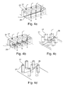
- the cooling channel 29 is a Forming flow of increased speed (see FIG. 4a ). It absorbs heat via heat transfer amplifier 21 and thus leads to the cooling of the component.
- the flow initially runs parallel to the wall 20 and is guided radially inwards or outwards in the direction of the inner or outer combustion chamber wall with respect to the combustion chamber or engine axis.
- openings 25 At the end of the channel are openings 25, which lead the air from the channel to the combustion chamber.
- FIG. 2 has no connection openings between the flow channel 29 and the volume 15.
- the necessary for rinsing the volume of air is achieved via openings 32 in the final boundary 13.
- the position of the openings is arbitrary, they can be arranged on the burner side or the compressor side.
- the axial length of this inflow to the damping volume can be varied between a few millimeters and several centimeters to optimize the individual damping effect (see also FIG. 2 and 8th ). It is important that the air from the main flow is fed directly into the volume, without first mixing with the cooling air for the heat shields. In this way, the two air volumes are kept separate.
- the air from the volume passes through the openings 17 in the combustion chamber, which lead through the heat transfer enhancing elements.
- FIG. 12 A similar design is in FIG. 12 shown.
- the cooling air is shown here as a solid arrow, the damping air as dashed and the starter film as a dotted arrow.
- the flow channel 29 can be connected to the volume 15 via openings 31 (see FIG. 8 ). These allow the volume to be flushed with air from the flow channel. The air can then enter the combustion chamber via the openings 17, which lead through the heat transfer-enhancing elements.
- both air streams intersect without mixing with each other.
- the heat shields may include further openings connecting the flow channel to the combustion chamber. These openings can be made at an angle of 10-90 ° to the surface and serve for film cooling of the heat shields.
- the volume 15 is preferably dimensioned so that a plenumnahe flow is ensured for the outlet bores. This occurs in the event that the flow of the outlet holes is no longer affected by the supply air. It can be chosen a distance of a minimum of 2mm to substantially the length of the burner head. If the distance between boundary 13 and wall 14 is selected as a function of an expected frequency, the volume acts as a resonator.
- the volume can be designed as a circumferentially continuous volume.
- the volume can be segmented by partitions both in the circumferential direction and in the radial direction or axial direction. In the case of a segmented volume, the volumes can optionally be the same or optionally of different sizes.
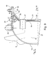
- the damping openings 17 do not have to be flush with the damping volume 15 facing side 14. You can protrude from the wall 14 in the volume 15 (see FIG. 12 ). Thus, the length of the damping openings can be adjusted depending on the resonance frequencies. The ratio of the cross-sectional area of the opening 17 and the length of the opening 17 can be selected as a function of a frequency. The number of openings per burner sector can vary from 1 to 1000. An inventive embodiment with only one damping opening is in FIG. 9 and 10 shown. Optionally, in this arrangement, heat transfer enhancing elements 21 (see FIG. 9 ) be used.
- individual or groups of exit holes 17 may pass through individual heat transfer enhancing elements 21.
- the elements can be arranged arbitrarily.
- the cross section of the elements can be arbitrarily shaped.
- the function can be further optimized thereby. Illustrated in FIG 3d figure and 4d one aerodynamic profile and in FIG. 3e and 4e a circular profile. Rectangular, diamond-shaped, hexagonal, elliptical, prismatic profiles are also conceivable. Also, a combination of the above profiles can be used as well as profiles that are formed from the intersection of circle segments.
- all or parts of the heat transfer enhancing elements may be made with damping openings.
- the entire combustion chamber is preferably connected via the combustion chamber head with a pin-shaped suspension 38 to the combustion chamber housing 8 or 9.
- the design of the combustion chamber head can optionally be made in one piece as an integral component, or optionally in several parts of several segments (see FIG. 11 , here by way of example 18 pieces) are executed.
- the combustion chamber walls 18 can be connected to the combustion chamber head 5 via fastening elements 23.
- Other connections of the combustion chamber to the combustion chamber housing (s) are possible according to the prior art.
- the intermediate gaps can be sealed with sealing strips (according to the prior art for turbine air guide vanes).
- an initial cooling film may be placed on the combustion chamber wall 18.
- the heat shields 20 employed in the direction of the combustion chamber wall outlet openings (25 in FIG. 9 and 12 ) that support the formation of a first cooling film (vertical, as shown in Figure 37) or replace.
- a primary, fresh cooling film is formed through inlet openings 34 along the connection arms 41 of the heat shields and / or from the combustion chamber wall 35.
- one or more sealing lips 40 are integrated according to the invention. They simultaneously serve for the axial positioning of the heat shields 20.
- combustion chamber wall can also be made in two walls, consisting of an inner wall 33 facing the hot gas and a side 18 facing the cold outer flow.
- the outer and inner combustion chamber walls can optionally be perforated.
- the formed between the outer and inner combustion chamber wall Volume may be interconnected by one or more flow channels with the air from the heat shields.
- One or more heat shields 20 may optionally be configured integrally with the combustion chamber head 5 or connected to the combustion chamber head via a frictional, positive or material connection.
- a frictional, positive or material connection In the Figures 2 and 8th is optionally a cohesive (eg welding, soldering) or a frictional (screw) connection on the boundary surrounding the burner provided.
- the heat shields can also be connected axially via webs and nuts to the combustion chamber head according to the prior art.
- the illustrated embodiment is advantageous in the Figures 9 and 12 in which the heat shields are fastened radially by means of flexible connecting arms 41 with the combustion chamber walls and the combustion chamber head through the connecting elements 23.
- the thermo-mechanical loads on the attachment arms 41 are reduced by the flexibility of the slots 39.
- the slots 39 simultaneously serve to cool the fasteners 23 and provide the primary initiator film 36 with fresh cooling air.
- FIG. 4b Other forms of the heat transfer enhancing elements are in the FIG. 4b shown. So ribs, cylinders, or indentations can be applied to the heat shield. The elements may optionally be applied to the heat shield 20 or the perforated wall 19.
- the opening 25 of the flow channel 29 directed toward the combustion chamber can be designed with a flow-guiding heat shield lip 30 (FIG. FIG. 5 ).
- the heat shield lip may include circumferential ribs on the side facing the flow channel 29.
Landscapes
- Engineering & Computer Science (AREA)
- Chemical & Material Sciences (AREA)
- Combustion & Propulsion (AREA)
- Mechanical Engineering (AREA)
- General Engineering & Computer Science (AREA)
- Turbine Rotor Nozzle Sealing (AREA)
- Gas Burners (AREA)
Priority Applications (2)
| Application Number | Priority Date | Filing Date | Title |
|---|---|---|---|
| EP11006812A EP2559942A1 (fr) | 2011-08-19 | 2011-08-19 | Tête de chambre de combustion d'une turbine à gaz dotée d'un refroidissement et d'un amortissement |
| US13/587,663 US20130042627A1 (en) | 2011-08-19 | 2012-08-16 | Combustion chamber head of a gas turbine with cooling and damping functions |
Applications Claiming Priority (1)
| Application Number | Priority Date | Filing Date | Title |
|---|---|---|---|
| EP11006812A EP2559942A1 (fr) | 2011-08-19 | 2011-08-19 | Tête de chambre de combustion d'une turbine à gaz dotée d'un refroidissement et d'un amortissement |
Publications (1)
| Publication Number | Publication Date |
|---|---|
| EP2559942A1 true EP2559942A1 (fr) | 2013-02-20 |
Family
ID=44650828
Family Applications (1)
| Application Number | Title | Priority Date | Filing Date |
|---|---|---|---|
| EP11006812A Withdrawn EP2559942A1 (fr) | 2011-08-19 | 2011-08-19 | Tête de chambre de combustion d'une turbine à gaz dotée d'un refroidissement et d'un amortissement |
Country Status (2)
| Country | Link |
|---|---|
| US (1) | US20130042627A1 (fr) |
| EP (1) | EP2559942A1 (fr) |
Cited By (5)
| Publication number | Priority date | Publication date | Assignee | Title |
|---|---|---|---|---|
| WO2015176887A1 (fr) | 2014-05-19 | 2015-11-26 | Siemens Aktiengesellschaft | Ensemble formant brûleur à résonateur |
| EP3002518A1 (fr) * | 2014-09-30 | 2016-04-06 | Alstom Technology Limited | Panneau avant de chambre de combustion |
| DE102015218677A1 (de) | 2015-09-29 | 2017-03-30 | Siemens Aktiengesellschaft | Brenneranordnung mit Resonator |
| WO2017055187A1 (fr) * | 2015-09-29 | 2017-04-06 | Siemens Aktiengesellschaft | Ensemble de brûleurs pour une chambre de combustion annulaire dotée de résonateurs |
| CN109556136A (zh) * | 2017-09-25 | 2019-04-02 | 通用电气公司 | 燃气涡轮组件及用于抑制其的压力脉动的方法 |
Families Citing this family (34)
| Publication number | Priority date | Publication date | Assignee | Title |
|---|---|---|---|---|
| WO2014163669A1 (fr) * | 2013-03-13 | 2014-10-09 | Rolls-Royce Corporation | Ensemble chambre de combustion pour turbine à gaz |
| GB2524265A (en) * | 2014-03-18 | 2015-09-23 | Rolls Royce Plc | An annular combustion chamber upstream wall and heat shield arrangement |
| EP3026346A1 (fr) * | 2014-11-25 | 2016-06-01 | Alstom Technology Ltd | Chemise de chambre de combustion |
| US10513984B2 (en) | 2015-08-25 | 2019-12-24 | General Electric Company | System for suppressing acoustic noise within a gas turbine combustor |
| US10197275B2 (en) | 2016-05-03 | 2019-02-05 | General Electric Company | High frequency acoustic damper for combustor liners |
| US10584610B2 (en) * | 2016-10-13 | 2020-03-10 | General Electric Company | Combustion dynamics mitigation system |
| GB2558566B (en) * | 2017-01-05 | 2019-11-13 | Rolls Royce Plc | A combustion chamber arrangement |
| US10663170B2 (en) * | 2017-01-19 | 2020-05-26 | Doosan Heavy Industries Construction Co., Ltd. | Flow conditioner to reduce combustion dynamics in a combustion system |
| US10724739B2 (en) * | 2017-03-24 | 2020-07-28 | General Electric Company | Combustor acoustic damping structure |
| US10415480B2 (en) | 2017-04-13 | 2019-09-17 | General Electric Company | Gas turbine engine fuel manifold damper and method of dynamics attenuation |
| US20180313540A1 (en) * | 2017-05-01 | 2018-11-01 | General Electric Company | Acoustic Damper for Gas Turbine Engine Combustors |
| US11149948B2 (en) | 2017-08-21 | 2021-10-19 | General Electric Company | Fuel nozzle with angled main injection ports and radial main injection ports |
| GB201715366D0 (en) * | 2017-09-22 | 2017-11-08 | Rolls Royce Plc | A combustion chamber |
| US10330204B2 (en) * | 2017-11-10 | 2019-06-25 | Rolls-Royce Deutschland Ltd & Co Kg | Burner seal of a gas turbine and method for manufacturing the same |
| US11156162B2 (en) | 2018-05-23 | 2021-10-26 | General Electric Company | Fluid manifold damper for gas turbine engine |
| US10823415B2 (en) * | 2018-06-01 | 2020-11-03 | Raytheon Technologies Corporation | Deflector for combustor of gas turbine engine |
| DE102018212394B4 (de) * | 2018-07-25 | 2024-03-28 | Rolls-Royce Deutschland Ltd & Co Kg | Brennkammerbaugruppe mit Strömungsleiteinrichtung aufweisendem Wandelement |
| US11506125B2 (en) | 2018-08-01 | 2022-11-22 | General Electric Company | Fluid manifold assembly for gas turbine engine |
| JP2020056542A (ja) * | 2018-10-02 | 2020-04-09 | 川崎重工業株式会社 | 航空機用のアニュラ型ガスタービン燃焼器 |
| US11174792B2 (en) * | 2019-05-21 | 2021-11-16 | General Electric Company | System and method for high frequency acoustic dampers with baffles |
| US11156164B2 (en) * | 2019-05-21 | 2021-10-26 | General Electric Company | System and method for high frequency accoustic dampers with caps |
| US11486262B2 (en) * | 2021-03-03 | 2022-11-01 | General Electric Company | Diffuser bleed assembly |
| US11686474B2 (en) * | 2021-03-04 | 2023-06-27 | General Electric Company | Damper for swirl-cup combustors |
| CN116293795B (zh) * | 2021-12-06 | 2025-05-16 | 通用电气阿维奥有限责任公司 | 用于燃气涡轮燃烧器应用的圆顶集成声学阻尼器 |
| CN116772238B (zh) * | 2022-03-08 | 2025-11-25 | 通用电气公司 | 圆顶-导流器接头冷却布置 |
| CN116928696A (zh) * | 2022-03-31 | 2023-10-24 | 通用电气公司 | 用于燃烧器的衬套组件 |
| CN117109030B (zh) | 2022-05-16 | 2025-09-19 | 通用电气公司 | 燃烧器衬里中的热声阻尼器 |
| CN117917528A (zh) * | 2022-10-20 | 2024-04-23 | 通用电气公司 | 用于燃烧器的整流罩阻尼器 |
| US12158270B2 (en) * | 2022-12-20 | 2024-12-03 | General Electric Company | Gas turbine engine combustor with a set of dilution passages |
| US12590702B2 (en) * | 2022-12-20 | 2026-03-31 | General Electric Company | Gas turbine engine combustor with a set of dilution passages |
| JP2024091024A (ja) * | 2022-12-23 | 2024-07-04 | 川崎重工業株式会社 | ガスタービンの燃焼器 |
| GB202312110D0 (en) * | 2023-08-08 | 2023-09-20 | Rolls Royce Plc | Combustor assembly |
| CN117128539B (zh) * | 2023-08-10 | 2026-05-05 | 中国航发四川燃气涡轮研究院 | 一种挡溅盘组件及其应用的火焰筒头部结构 |
| US20250189130A1 (en) * | 2023-12-07 | 2025-06-12 | General Electric Company | Gas turbine engine and combustor therefor |
Citations (13)
| Publication number | Priority date | Publication date | Assignee | Title |
|---|---|---|---|---|
| US4686823A (en) * | 1986-04-28 | 1987-08-18 | United Technologies Corporation | Sliding joint for an annular combustor |
| WO1992016798A1 (fr) | 1991-03-22 | 1992-10-01 | Rolls-Royce Plc | Bruleur de turbine a gaz |
| EP0576717A1 (fr) | 1992-07-03 | 1994-01-05 | Abb Research Ltd. | Chambre de combustion de turbine à gaz |
| DE4427222A1 (de) | 1994-08-01 | 1996-02-08 | Bmw Rolls Royce Gmbh | Hitzeschild für eine Gasturbinen-Brennkammer |
| EP0724119A2 (fr) * | 1995-01-26 | 1996-07-31 | General Electric Company | DÔme pour une chambre de combustion d'une turbine à gaz |
| EP0971172B1 (fr) | 1998-07-10 | 2003-12-03 | ALSTOM (Switzerland) Ltd | Chambre de combustion pour turbine à gaz avec paroi à structure silencieuse |
| EP1612769A2 (fr) * | 2004-06-28 | 2006-01-04 | United Technologies Corporation | Revêtement acoustique à haute admittance |
| EP1666795A1 (fr) * | 2004-11-24 | 2006-06-07 | Rolls-Royce Plc | Atténuateur acoustique |
| US20070169992A1 (en) | 2006-01-25 | 2007-07-26 | Siemens Power Generation, Inc. | Acoustic resonator with impingement cooling tubes |
| EP1865259A2 (fr) * | 2006-06-09 | 2007-12-12 | Rolls-Royce Deutschland Ltd & Co KG | Paroi de chambre de combustion de turbine à gaz pour une chambre de turbine à gaz à combustion pauvre |
| CA2627627A1 (fr) | 2007-06-22 | 2008-12-22 | Honeywell International Inc. | Protecteurs thermiques pour utilisation dans des chambres de combustion |
| EP2273196A2 (fr) * | 2009-07-08 | 2011-01-12 | Rolls-Royce Deutschland Ltd & Co KG | Tête pour chambre de combustion d'une turbine à gaz |
| EP2385303A1 (fr) * | 2010-05-03 | 2011-11-09 | Alstom Technology Ltd | Dispositif de combustion pour turbine à gaz |
Family Cites Families (3)
| Publication number | Priority date | Publication date | Assignee | Title |
|---|---|---|---|---|
| FR2751731B1 (fr) * | 1996-07-25 | 1998-09-04 | Snecma | Ensemble bol-deflecteur pour chambre de combustion de turbomachine |
| US6530221B1 (en) * | 2000-09-21 | 2003-03-11 | Siemens Westinghouse Power Corporation | Modular resonators for suppressing combustion instabilities in gas turbine power plants |
| US20100300107A1 (en) * | 2009-05-29 | 2010-12-02 | General Electric Company | Method and flow sleeve profile reduction to extend combustor liner life |
-
2011
- 2011-08-19 EP EP11006812A patent/EP2559942A1/fr not_active Withdrawn
-
2012
- 2012-08-16 US US13/587,663 patent/US20130042627A1/en not_active Abandoned
Patent Citations (14)
| Publication number | Priority date | Publication date | Assignee | Title |
|---|---|---|---|---|
| US4686823A (en) * | 1986-04-28 | 1987-08-18 | United Technologies Corporation | Sliding joint for an annular combustor |
| WO1992016798A1 (fr) | 1991-03-22 | 1992-10-01 | Rolls-Royce Plc | Bruleur de turbine a gaz |
| EP0576717A1 (fr) | 1992-07-03 | 1994-01-05 | Abb Research Ltd. | Chambre de combustion de turbine à gaz |
| DE4427222A1 (de) | 1994-08-01 | 1996-02-08 | Bmw Rolls Royce Gmbh | Hitzeschild für eine Gasturbinen-Brennkammer |
| EP0724119A2 (fr) * | 1995-01-26 | 1996-07-31 | General Electric Company | DÔme pour une chambre de combustion d'une turbine à gaz |
| EP0971172B1 (fr) | 1998-07-10 | 2003-12-03 | ALSTOM (Switzerland) Ltd | Chambre de combustion pour turbine à gaz avec paroi à structure silencieuse |
| EP1612769A2 (fr) * | 2004-06-28 | 2006-01-04 | United Technologies Corporation | Revêtement acoustique à haute admittance |
| EP1666795A1 (fr) * | 2004-11-24 | 2006-06-07 | Rolls-Royce Plc | Atténuateur acoustique |
| US20070169992A1 (en) | 2006-01-25 | 2007-07-26 | Siemens Power Generation, Inc. | Acoustic resonator with impingement cooling tubes |
| EP1865259A2 (fr) * | 2006-06-09 | 2007-12-12 | Rolls-Royce Deutschland Ltd & Co KG | Paroi de chambre de combustion de turbine à gaz pour une chambre de turbine à gaz à combustion pauvre |
| CA2627627A1 (fr) | 2007-06-22 | 2008-12-22 | Honeywell International Inc. | Protecteurs thermiques pour utilisation dans des chambres de combustion |
| EP2273196A2 (fr) * | 2009-07-08 | 2011-01-12 | Rolls-Royce Deutschland Ltd & Co KG | Tête pour chambre de combustion d'une turbine à gaz |
| DE102009032277A1 (de) | 2009-07-08 | 2011-01-20 | Rolls-Royce Deutschland Ltd & Co Kg | Brennkammerkopf einer Gasturbine |
| EP2385303A1 (fr) * | 2010-05-03 | 2011-11-09 | Alstom Technology Ltd | Dispositif de combustion pour turbine à gaz |
Non-Patent Citations (1)
| Title |
|---|
| "J. Fluid Mech.", vol. 485, 2003, CAMBRIDGE UNIVERSITY PRESS, article "The absorption of axial acoustic waves by a perforated liner with bias flow", pages: 307 - 335 |
Cited By (10)
| Publication number | Priority date | Publication date | Assignee | Title |
|---|---|---|---|---|
| WO2015176887A1 (fr) | 2014-05-19 | 2015-11-26 | Siemens Aktiengesellschaft | Ensemble formant brûleur à résonateur |
| US10605457B2 (en) | 2014-05-19 | 2020-03-31 | Siemens Aktiengesellschaft | Burner arrangement with resonator |
| EP3002518A1 (fr) * | 2014-09-30 | 2016-04-06 | Alstom Technology Limited | Panneau avant de chambre de combustion |
| CN105465830A (zh) * | 2014-09-30 | 2016-04-06 | 阿尔斯通技术有限公司 | 燃烧器前面板 |
| US10107496B2 (en) | 2014-09-30 | 2018-10-23 | Ansaldo Energia Switzerland AG | Combustor front panel |
| CN105465830B (zh) * | 2014-09-30 | 2020-06-05 | 安萨尔多能源瑞士股份公司 | 燃烧器前面板 |
| DE102015218677A1 (de) | 2015-09-29 | 2017-03-30 | Siemens Aktiengesellschaft | Brenneranordnung mit Resonator |
| WO2017055187A1 (fr) * | 2015-09-29 | 2017-04-06 | Siemens Aktiengesellschaft | Ensemble de brûleurs pour une chambre de combustion annulaire dotée de résonateurs |
| CN109556136A (zh) * | 2017-09-25 | 2019-04-02 | 通用电气公司 | 燃气涡轮组件及用于抑制其的压力脉动的方法 |
| CN109556136B (zh) * | 2017-09-25 | 2021-12-24 | 通用电气公司 | 燃气涡轮组件及用于抑制其的压力脉动的方法 |
Also Published As
| Publication number | Publication date |
|---|---|
| US20130042627A1 (en) | 2013-02-21 |
Similar Documents
| Publication | Publication Date | Title |
|---|---|---|
| EP2273196A2 (fr) | Tête pour chambre de combustion d'une turbine à gaz | |
| DE69929282T2 (de) | Brennkammer | |
| DE69919298T2 (de) | Kühlstruktur für eine Gasturbinenbrennkammer | |
| DE69210118T2 (de) | Aufbau eines Brennkammerdomes | |
| EP2154431B1 (fr) | Machine thermique | |
| DE10001109B4 (de) | Gekühlte Schaufel für eine Gasturbine | |
| EP2340397B1 (fr) | Pièce du brûleur pour une chambre de combustion d'une turbine à gaz et turbine à gaz | |
| EP1865259A2 (fr) | Paroi de chambre de combustion de turbine à gaz pour une chambre de turbine à gaz à combustion pauvre | |
| EP2775131B1 (fr) | Amortisseur acoustique d'un turbocompresseur à gaz d'échappement | |
| DE102005025823A1 (de) | Verfahren und Vorrichtung zum Kühlen einer Brennkammerauskleidung und eines Übergangsteils einer Gasturbine | |
| CH709993A2 (de) | Stromabwärtige Düse in einer Brennkammer einer Verbrennungsturbine. | |
| CH680523A5 (fr) | ||
| DE19538746B4 (de) | Segmentierter Mittelkörper für eine Doppelring-Brennkammer | |
| CH697920A2 (de) | Turbinentriebwerk mit einer Brennkammerauskleidung mit wirbelluftgekühltem hinterem Ende und Kühlverfahren. | |
| EP1832812A2 (fr) | Paroi de chambre de combustion de turbine à gaz avec amortissement des vibrations de la chambre de combustion | |
| EP3117148B1 (fr) | Système de combustion avec résonateur | |
| EP0971172B1 (fr) | Chambre de combustion pour turbine à gaz avec paroi à structure silencieuse | |
| DE102008016931A1 (de) | System zur Reduktion der Brennkammerdynamik | |
| CH702172A2 (de) | Brennkammer für eine Gasturbine ,mit verbesserter Kühlung. | |
| EP1048898B1 (fr) | Brûleur | |
| DE112015003440T5 (de) | Zylinder für Brennkammer, Brennkammer und Gasturbine | |
| EP3219918B1 (fr) | Turbine a gaz avec un dispositif de refroidissement de plateformes d'une couronne d'aubes directrices de la turbine à gaz | |
| DE102015113146A1 (de) | Systeme und Vorrichtungen im Zusammenhang mit Gasturbinenbrennkammern | |
| EP0990851B1 (fr) | Chambre de combustion pour une turbine à gaz | |
| EP1510667A2 (fr) | Silencieux |
Legal Events
| Date | Code | Title | Description |
|---|---|---|---|
| PUAI | Public reference made under article 153(3) epc to a published international application that has entered the european phase |
Free format text: ORIGINAL CODE: 0009012 |
|
| AK | Designated contracting states |
Kind code of ref document: A1 Designated state(s): AL AT BE BG CH CY CZ DE DK EE ES FI FR GB GR HR HU IE IS IT LI LT LU LV MC MK MT NL NO PL PT RO RS SE SI SK SM TR |
|
| AX | Request for extension of the european patent |
Extension state: BA ME |
|
| 17P | Request for examination filed |
Effective date: 20130422 |
|
| 17Q | First examination report despatched |
Effective date: 20130610 |
|
| STAA | Information on the status of an ep patent application or granted ep patent |
Free format text: STATUS: THE APPLICATION IS DEEMED TO BE WITHDRAWN |
|
| 18D | Application deemed to be withdrawn |
Effective date: 20140925 |