EP2559976A1 - Débitmètre massique Coriolis - Google Patents
Débitmètre massique Coriolis Download PDFInfo
- Publication number
- EP2559976A1 EP2559976A1 EP12002044A EP12002044A EP2559976A1 EP 2559976 A1 EP2559976 A1 EP 2559976A1 EP 12002044 A EP12002044 A EP 12002044A EP 12002044 A EP12002044 A EP 12002044A EP 2559976 A1 EP2559976 A1 EP 2559976A1
- Authority
- EP
- European Patent Office
- Prior art keywords
- measuring tube
- turn
- coriolis mass
- mass flowmeter
- region
- Prior art date
- Legal status (The legal status is an assumption and is not a legal conclusion. Google has not performed a legal analysis and makes no representation as to the accuracy of the status listed.)
- Granted
Links
Images


Classifications
-
- G—PHYSICS
- G01—MEASURING; TESTING
- G01F—MEASURING VOLUME, VOLUME FLOW, MASS FLOW OR LIQUID LEVEL; METERING BY VOLUME
- G01F1/00—Measuring the volume flow or mass flow of fluid or fluent solid material wherein the fluid passes through a meter in a continuous flow
- G01F1/76—Devices for measuring mass flow of a fluid or a fluent solid material
- G01F1/78—Direct mass flowmeters
- G01F1/80—Direct mass flowmeters operating by measuring pressure, force, momentum, or frequency of a fluid flow to which a rotational movement has been imparted
- G01F1/84—Coriolis or gyroscopic mass flowmeters
- G01F1/845—Coriolis or gyroscopic mass flowmeters arrangements of measuring means, e.g., of measuring conduits
- G01F1/8468—Coriolis or gyroscopic mass flowmeters arrangements of measuring means, e.g., of measuring conduits vibrating measuring conduits
- G01F1/8481—Coriolis or gyroscopic mass flowmeters arrangements of measuring means, e.g., of measuring conduits vibrating measuring conduits having loop-shaped measuring conduits, e.g. the measuring conduits form a loop with a crossing point
- G01F1/8486—Coriolis or gyroscopic mass flowmeters arrangements of measuring means, e.g., of measuring conduits vibrating measuring conduits having loop-shaped measuring conduits, e.g. the measuring conduits form a loop with a crossing point with multiple measuring conduits
-
- G—PHYSICS
- G01—MEASURING; TESTING
- G01F—MEASURING VOLUME, VOLUME FLOW, MASS FLOW OR LIQUID LEVEL; METERING BY VOLUME
- G01F1/00—Measuring the volume flow or mass flow of fluid or fluent solid material wherein the fluid passes through a meter in a continuous flow
- G01F1/76—Devices for measuring mass flow of a fluid or a fluent solid material
- G01F1/78—Direct mass flowmeters
- G01F1/80—Direct mass flowmeters operating by measuring pressure, force, momentum, or frequency of a fluid flow to which a rotational movement has been imparted
- G01F1/84—Coriolis or gyroscopic mass flowmeters
- G01F1/8409—Coriolis or gyroscopic mass flowmeters constructional details
- G01F1/8413—Coriolis or gyroscopic mass flowmeters constructional details means for influencing the flowmeter's motional or vibrational behaviour, e.g., conduit support or fixing means, or conduit attachments
-
- G—PHYSICS
- G01—MEASURING; TESTING
- G01F—MEASURING VOLUME, VOLUME FLOW, MASS FLOW OR LIQUID LEVEL; METERING BY VOLUME
- G01F1/00—Measuring the volume flow or mass flow of fluid or fluent solid material wherein the fluid passes through a meter in a continuous flow
- G01F1/76—Devices for measuring mass flow of a fluid or a fluent solid material
- G01F1/78—Direct mass flowmeters
- G01F1/80—Direct mass flowmeters operating by measuring pressure, force, momentum, or frequency of a fluid flow to which a rotational movement has been imparted
- G01F1/84—Coriolis or gyroscopic mass flowmeters
- G01F1/8409—Coriolis or gyroscopic mass flowmeters constructional details
- G01F1/844—Coriolis or gyroscopic mass flowmeters constructional details microfluidic or miniaturised flowmeters
-
- G—PHYSICS
- G01—MEASURING; TESTING
- G01F—MEASURING VOLUME, VOLUME FLOW, MASS FLOW OR LIQUID LEVEL; METERING BY VOLUME
- G01F15/00—Details of, or accessories for, apparatus of groups G01F1/00 - G01F13/00 insofar as such details or appliances are not adapted to particular types of such apparatus
- G01F15/14—Casings, e.g. of special material
Definitions
- the invention relates to a Coriolis mass flowmeter with a flowed through by a medium measuring tube, with at least one actuator and at least one sensor, wherein the measuring tube is bent between its inlet end and its outlet end to a first turn and a second turn, the first turn and the second turn in a transition region of the measuring tube into each other, the first turn and the second turn in parallel winding planes and facing each other and wherein the first turn and the second turn in oscillatable areas of the actuator to the vibrations are excitable and the vibrations from the sensor are detectable.
- Coriolis mass flowmeters have been known for many years in very different configurations.
- the measuring tube through which a medium can flow or the measuring tubes through which a medium flows are excited by the actuator to a vibration which preferably corresponds to a natural frequency of the measuring tube in the installed position.
- Inlet and outlet side inertial forces have a different effect on the flowing medium in the measuring tube excited to vibrate and thus on the measuring tube itself, so that the deflection of the measuring tube on the inlet and outlet side is influenced differently.
- two sensors for detecting the vibrations are provided, namely spaced on the inlet and outlet side of the actuator, so that overall the vibrations of the measuring tube detected on the inlet and outlet side with the sensors have a phase shift which is a direct measure of the mass flow of interest.
- the measured quantity ⁇ e namely the mass flow rate, is derived from the phase shift.
- the input Coriolis mass flow meters presented have the advantage that they work only with a single measuring tube, but this measuring tube is bent to a first turn and a second turn, which face each other, so run virtually parallel to each other.
- the acting between the first turn and the second turn actuator directs the oscillatory areas of the first turn and the second turn in opposite directions - ie away from each other or towards each other - so that the center of gravity of the system is maintained altogether and from the outside, so from the connections forth, vibrations are virtually unrecognizable.
- the invention is therefore based on the object - to provide a - suitable in particular for the measurement of very small flow rates - Coriolis mass flowmeter, which is less sensitive to the coupling of external vibrations.
- the previously derived and indicated object is achieved in a generic Coriolis mass flowmeter in that the oscillatable regions of the first turn and the second turn are bent in a V-shape and open in each case in the direction of the transition region of the measuring tube.
- the legs of the V-shaped first turn and second turn diverge towards the transition region, the point or region where the legs come together, where they converge, so is away from the transition area.
- measuring tubes are used with an inner diameter of, for example, 1.2 mm and with a wall thickness of 0.2 mm.
- the height of the oscillatable region of an inventively designed measuring tube with V-shaped turns and with opening in the direction of the transition region of the measuring tube V-legs is then for example 60 mm, the open ends of the V-legs are then about 100 mm apart , In a measuring tube designed in this way, the smallest natural frequencies of over 100 Hz and even over 150 Hz can be achieved.
- the transition region of the measuring tube lies in a base plane, in particular the transitional design together with the inlet end and the outlet end of the measuring tube lies in a base plane.
- the legs of the V-bendable oscillatory region of the first turn and / or the second turn include identical angles with the base plane so that the V-shaped swingable region extends symmetrically across the transition region of the measuring tube, the legs increasing with increasing Distance from the transition area converge slowly, in contrast to ⁇ -shaped measuring tubes, in which the ⁇ -legs would arise virtually centrally in the transition area and with increasing distance from the transition area would first diverge and then ultimately run together again to a closed turn ,
- the oscillatory regions of the first turn and the second turn are bent in a V-shape
- this essentially means that the legs of the measuring tube bent in a V-shaped manner in this region converge at one end and at the other Run apart at the end. It is less important with which radius of curvature the V-shaped area is closed at the closed end of the "V".
- the measuring tube does not terminate at the open ends of the V-legs of the measuring tube, but ends there the oscillatable region of the first turn formed by the curved measuring tube or the second winding, for example by the oscillation of the measuring tube is defined at these locations defined by a node plate or prevented.
- the propagation of interfering vibrations can be further reduced by providing the measuring tube in the transition region between the first turn and the second turn with a central mass and / or firmly connecting the measuring tube in the transition region to a housing of the Coriolis mass flowmeter is.
- both measures are taken, that is, the measuring tube in the transition region both firmly connected to a central mass, said central mass is additionally firmly connected to the housing of the Coriolis mass flowmeter.
- the measuring tube in the inlet region with an inlet region mass and / or the equipment of the measuring tube in the outlet region with an outlet region mass.
- the metering tube in the inlet area can be fixedly connected to a housing of the Coriolis mass flowmeter and / or the metering tube in the outlet area can be firmly connected to a housing of the Coriolis mass flowmeter, but preferably a mass is provided in the inlet area and / or in the outlet area additionally firmly connected to the housing of the Coriolis mass flowmeter.
- vibrations introduced via the connected external process pipes can be effectively absorbed.
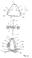
- Coriolis mass flowmeters 1 according to the invention which have a measuring tube 2 through which a medium can flow, the configuration and the course of the measuring tube 2 being of particular interest in the present case. For this reason is in the Fig. 1a . 2a and 3a in each case essentially only the measuring tube 2 and relevant attachments shown.
- These add-on parts include, inter alia, an actuator 3 and in the present case two sensors 4a, 4b, which serve to detect the vibrations of the measuring tube 2.
- the illustrated Coriolis mass flowmeters 1 are characterized in that they have only a single measuring tube 2, which is bent in each case between its inlet end 5 and its outlet end 6 to form a first turn 7 and a second turn 8 the first measuring tube 2 is present, the first winding 7 and the second winding 8 are connected to each other in a transition region 9 of the measuring tube 2 or go into the first turn 7 and the second turn 8 in this transition region 9 into each other.
- the first turn 7 and the second turn 8 run in parallel winding planes, which can be seen clearly in the plan view in particular Fig. 1a . 2a and 3a (middle illustration in each case).
- Fig. 1 to 3 is also the particular shape of the oscillatory regions 10, 11 of the first turn 7 and the second turn 8 recognizable, which results from the fact that these oscillatable regions 10, 11 are bent in a V-shape and each in the direction of the transition region 9 of the measuring tube 2 open, which is of particular importance.
- the advantage of the V-shaped measuring tube in the two oscillatable regions 10, 11 lies in the fact that with the windings 7, 8 configured in this way, higher minimum natural frequencies can be achieved than with differently shaped measuring tubes 2. Investigations have shown that, for example, ⁇ -shaped or circular windings have lower natural frequencies in the oscillatable regions with otherwise identical measuring tube properties, which is disadvantageous especially in the case of the unwanted coupling of external vibrations.
- the illustrated embodiments also have in common that the transition region 9 of the measuring tube 2 is located in a base plane, the measuring tube 2 in the transition region 9 thus extends in a plane and is not spatially extending in its course.
- the inlet end 5 and the outlet end 6 are in the illustrated variants in the same base plane.
- the embodiments illustrated in the figures is also common that all legs 12, 13, the sake of clarity, only in the upper part of the figures Fig. 1a . 2a and 3a are shown, the V-shaped bent oscillatable areas 10, 11 of the first turn 7 and the second turn 8 with the base plane identical angles include, is understood by the angle enclosed between the legs 12, 13 and the base plane angle is always the smallest angle to the base plane. Overall, this achieves that the oscillatable regions 10, 11 of the first turn 7 and the second turn 8 in the present cases rise symmetrically above the base plane.
- the actuator 3 is in each case connected to that region of the first turn 7 and the second turn 8, in which the legs 12, 13 of the respective V-shaped oscillatable regions 10, 11 converge, ie in the top of the V-shaped regions.
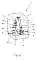
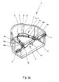
- Fig. 3 illustrated embodiment differs from the other two embodiments, inter alia, that the transition region 9 of the measuring tube 2 is designed there S-shaped, wherein the transition region 9 not only runs between the winding planes, but crosses these winding planes and over the limited between the winding planes area goes beyond (see in particular middle illustration in Fig. 3a ).
- the measuring tube 2 is provided in the transition region 9 with a central mass 14, this central mass 14 is additionally fixedly connected to a housing 15 of the Coriolis mass flowmeter 1.
- the measure serves to suppress oscillatory interaction between the first turn 7 and the second turn 8 of the measuring tube 2, since only the effect of the inertial forces on the respective turns 7 and 8 are of interest for determining the flow, other interactions between the turns 7 are also of interest and 8 are not desirable.
- the measuring tube 2 is provided in the inlet region with an additional inlet area mass 16, which is additionally fixedly connected to the housing 15 of the Coriolis Massr notebookillesmes réelles 1.
- the measuring tube 2 is provided in the outlet with a Auslass Schemesmasse 17, which also also with the housing 15 of the Coriolis mass flowmeter 1 is firmly connected.
- These masses also serve to prevent unwanted vibrations of the measuring tube 2, with the inlet region mass 16 and the outlet region mass 17 directed against the coupling of external oscillations coupled into the Coriolis mass flowmeter 1.
- a further measure is implemented in order to suppress disturbing vibrations of the transition region 9 of the measuring tube 2. Further suppression is achieved in that an inlet-side end of the transition region 9 of the measuring tube 2 is additionally connected to the inlet region mass 16 and via the inlet region mass 16 to the housing 15 of the Coriolis mass flowmeter 1 and an outlet-side end of the transition region 9 of the measuring tube 2 is additionally connected to the outlet region mass 17 - and above to the housing 15 of the Coriolis mass flowmeter 1-.
- the oscillatory region 10 of the first turn 7 and the oscillatable region 11 of the second turn 8 are delimited by two first node plates 18a, 18b disposed at the two spaced ends of the V-legs 12, 13 of the measuring tube 2 the first node plates 18a, 18b additionally interconnect the first turn 7 and the second turn 8. Due to the additional connection with the node plates 18a, 18b, the first turn 7 and the second turn 8 of the measuring tube 2 can no longer move relative to each other, so that an oscillation relevant to the measurement of the measuring tube 2 ends at the first node plates 18a, 18b or continues to form a node.
- These first node plates 18a, 18b are preferably still bent in a U-shape to have a particular rigidity against a bending moment introduced by the first turn 7 and the second turn 8 of the measuring tube 2 into the node plates 18a, 18b.
- two second node plates 19a, 19b are attached to the measuring tube 2
- a second node plate 19a is disposed between the inlet end 5 of the measuring tube 2 and the first node plate 18a near the inlet end 5, another second node plate 19b between the outlet end 6 of the measuring tube 2 and the first node plate 18b near the outlet end 6 of the measuring tube 2, the second node plates 19a, 19b forming the first coil 7 and the second coil 8 together.
- the illustrated Coriolis mass flowmeters 1 are intended for the detection of the smallest passages.
- the first winding 7 and the second winding 8 have a maximum winding diameter of less than 10 cm, with measuring tubes 2 having an inner diameter of 1.2 mm and a wall thickness of 0.2 mm are used.
Landscapes
- Physics & Mathematics (AREA)
- Fluid Mechanics (AREA)
- General Physics & Mathematics (AREA)
- Chemical & Material Sciences (AREA)
- Dispersion Chemistry (AREA)
- Measuring Volume Flow (AREA)
Applications Claiming Priority (2)
| Application Number | Priority Date | Filing Date | Title |
|---|---|---|---|
| DE102011110165 | 2011-08-16 | ||
| DE102011114569A DE102011114569A1 (de) | 2011-08-16 | 2011-09-30 | Coriolis-Massedurchflussmessgerät |
Publications (2)
| Publication Number | Publication Date |
|---|---|
| EP2559976A1 true EP2559976A1 (fr) | 2013-02-20 |
| EP2559976B1 EP2559976B1 (fr) | 2018-02-14 |
Family
ID=45939092
Family Applications (1)
| Application Number | Title | Priority Date | Filing Date |
|---|---|---|---|
| EP12002044.1A Active EP2559976B1 (fr) | 2011-08-16 | 2012-03-22 | Débitmètre massique Coriolis |
Country Status (5)
| Country | Link |
|---|---|
| US (1) | US8607643B2 (fr) |
| EP (1) | EP2559976B1 (fr) |
| CN (1) | CN102980621B (fr) |
| BR (1) | BR102012020494A2 (fr) |
| DE (1) | DE102011114569A1 (fr) |
Cited By (2)
| Publication number | Priority date | Publication date | Assignee | Title |
|---|---|---|---|---|
| EP3237784B1 (fr) * | 2014-12-22 | 2019-07-31 | Endress+Hauser Flowtec AG | Débitmètre massique ou densimètre à force de coriolis |
| EP2600122B1 (fr) * | 2011-12-02 | 2021-06-16 | Krohne AG | Débitmètre massique du type Coriolis |
Families Citing this family (23)
| Publication number | Priority date | Publication date | Assignee | Title |
|---|---|---|---|---|
| DE102011114569A1 (de) * | 2011-08-16 | 2013-02-21 | Krohne Ag | Coriolis-Massedurchflussmessgerät |
| WO2015026927A1 (fr) * | 2013-08-22 | 2015-02-26 | Malema Engineering Corporation | Procédé de fabrication de capteur de débit massique de coriolis à partir d'un matériau polymère |
| DE102013114731A1 (de) | 2013-12-20 | 2015-06-25 | Endress+Hauser Flowtec Ag | Spule |
| US9989391B2 (en) | 2013-12-20 | 2018-06-05 | Endress + Hauser Flowtec Ag | Coil |
| DE102014109116A1 (de) * | 2014-06-30 | 2015-12-31 | Krohne Ag | Coriolis-Massedurchflussmessgerät |
| KR102058587B1 (ko) * | 2015-03-25 | 2019-12-23 | 마이크로 모우션, 인코포레이티드 | 진동 유량계에서 브레이즈 조인트 응력을 감소시키기 위한 장치 및 방법 |
| DE102017106375A1 (de) * | 2017-03-24 | 2018-09-27 | Krohne Ag | Durchflussmessgerät |
| DE102017121157A1 (de) | 2017-08-09 | 2019-02-14 | Endress+Hauser Flowtec Ag | Spule sowie Meßwandler mit einer solchen Spule |
| DE102017131199A1 (de) | 2017-12-22 | 2019-06-27 | Endress + Hauser Flowtec Ag | Coriolis-Massendurchfluß-Meßgerät |
| DE102018105089A1 (de) * | 2018-03-06 | 2019-09-12 | Endress+Hauser Flowtec Ag | Coriolismessgerät |
| CN113242960B (zh) | 2018-12-20 | 2024-05-14 | 恩德斯+豪斯流量技术股份有限公司 | 科里奥利质量流量计 |
| DE102018133117A1 (de) | 2018-12-20 | 2020-06-25 | Endress+Hauser Flowtec Ag | Coriolis-Massendurchfluß-Meßgerät |
| EP3899448B1 (fr) | 2018-12-21 | 2024-03-27 | Endress + Hauser Flowtec AG | Débitmètre massique à effet coriolis muni d'un détecteur de champ magnétique |
| DE102019107601A1 (de) * | 2019-03-25 | 2020-10-01 | Endress + Hauser Flowtec Ag | Coriolis-Messaufnehmer und Coriolis-Messgerät |
| CN111795729B (zh) * | 2019-04-08 | 2023-03-17 | 高准有限公司 | 流量计的壳体和包括该壳体的流量计 |
| DE102019133610A1 (de) | 2019-12-09 | 2021-06-10 | Endress + Hauser Flowtec Ag | Vibronisches Meßsystem zum Messen eines Massestroms eines fluiden Meßstoff |
| US20230137451A1 (en) * | 2021-11-02 | 2023-05-04 | Malema Engineering Corporation | Heavy cradle for replaceable coriolis flow sensors |
| US11619532B2 (en) | 2020-04-10 | 2023-04-04 | Malema Engineering Corporation | Replaceable, gamma sterilizable Coriolis flow sensors |
| US11300435B2 (en) | 2020-04-10 | 2022-04-12 | Malema Engineering Corporation | Coriolis mass flow sensors having different resonant frequencies |
| DE102020127382A1 (de) | 2020-10-16 | 2022-04-21 | Endress+Hauser Flowtec Ag | Verfahren zum Überprüfen eines vibronischen Meßsystems |
| DE102022112523A1 (de) | 2022-05-18 | 2023-11-23 | Endress+Hauser Flowtec Ag | Vibronisches Meßsystem |
| DE102022116111A1 (de) | 2022-06-28 | 2023-12-28 | Endress+Hauser Flowtec Ag | Vibronisches Meßsystem |
| US12372390B2 (en) | 2023-05-08 | 2025-07-29 | Malema Engineering Corporation | Coriolis mass flow rate sensor |
Citations (4)
| Publication number | Priority date | Publication date | Assignee | Title |
|---|---|---|---|---|
| US5501106A (en) * | 1993-11-16 | 1996-03-26 | Lew; Hyok S. | Inertia force flowmeter with pivotally supported vibrating conduit |
| DE29511888U1 (de) * | 1995-07-22 | 1996-11-21 | Bopp & Reuther Messtechnik GmbH, 68305 Mannheim | Meßgerät zur Messung des Masseflusses eines strömenden Mediums |
| US5996225A (en) * | 1997-03-11 | 1999-12-07 | Micro Motion, Inc. | Method for manufacturing a dual loop coriolis effect mass flowmeter |
| US20110094312A1 (en) * | 2009-10-27 | 2011-04-28 | Endress + Hauser Flowtec Ag | Measuring transducer of vibration type |
Family Cites Families (16)
| Publication number | Priority date | Publication date | Assignee | Title |
|---|---|---|---|---|
| US5423221A (en) | 1986-02-11 | 1995-06-13 | Abb K-Flow Inc. | Mass flow measuring device |
| EP0239679B1 (fr) | 1986-04-04 | 1988-09-07 | Krohne Messtechnik Gmbh & Co. Kg | Débitmètre massique pour fluide avec détecteur des forces de Coriolis |
| EP0271605B1 (fr) | 1986-10-02 | 1990-12-27 | Krohne AG | Appareil pour mesurer le débit massique avec dispositif d'investigation de la force de coriolis |
| US5271281A (en) | 1986-10-28 | 1993-12-21 | The Foxboro Company | Coriolis-type mass flowmeter |
| EP0462711A1 (fr) * | 1990-06-16 | 1991-12-27 | Imperial Chemical Industries Plc | Débitmètre pour fluides |
| US5675093A (en) | 1995-09-13 | 1997-10-07 | Endress+Hauser Flowtec Ag | Coriolis mass flow sensor including a single connection and support structure |
| DE29709692U1 (de) | 1997-06-04 | 1997-07-31 | Elsen, Ulrich, Dipl.-Ing., 47057 Duisburg | Hochtemperatur Masse-Durchflußmesser |
| JP2951651B1 (ja) * | 1998-07-29 | 1999-09-20 | 株式会社オーバル | コリオリ質量流量計及びその製造方法 |
| DE50004243D1 (de) * | 2000-03-01 | 2003-12-04 | Flowtec Ag | Coriolis-Massedurchfluss/Dichteaufnehmer mit einem einzigen gebogenen Messrohr |
| US6711958B2 (en) | 2000-05-12 | 2004-03-30 | Endress + Hauser Flowtec Ag | Coriolis mass flow rate/density/viscoy sensor with two bent measuring tubes |
| DK1154243T3 (da) * | 2000-05-12 | 2007-04-02 | Flowtec Ag | Coriolis massegennemströmningsmåler med to buede målerör |
| JP5039654B2 (ja) | 2008-07-09 | 2012-10-03 | 株式会社キーエンス | 流量計 |
| DE102008037700A1 (de) | 2008-08-14 | 2010-02-18 | Endress + Hauser Flowtec Ag | Messaufnehmer vom Vibrationstyp |
| EP2659236B1 (fr) * | 2010-12-30 | 2019-07-03 | Endress+Hauser Flowtec AG | Détecteur de type a vibrations et système de mesure le comprenant |
| EP2705334B1 (fr) * | 2011-05-02 | 2018-01-24 | Endress+Hauser Flowtec AG | Capteur de mesure de type vibratoire et système de mesure formé avec ce capteur de mesure |
| DE102011114569A1 (de) * | 2011-08-16 | 2013-02-21 | Krohne Ag | Coriolis-Massedurchflussmessgerät |
-
2011
- 2011-09-30 DE DE102011114569A patent/DE102011114569A1/de not_active Withdrawn
-
2012
- 2012-03-22 EP EP12002044.1A patent/EP2559976B1/fr active Active
- 2012-04-03 US US13/438,165 patent/US8607643B2/en active Active
- 2012-08-15 BR BR102012020494-0A patent/BR102012020494A2/pt not_active IP Right Cessation
- 2012-08-16 CN CN201210291841.3A patent/CN102980621B/zh active Active
Patent Citations (4)
| Publication number | Priority date | Publication date | Assignee | Title |
|---|---|---|---|---|
| US5501106A (en) * | 1993-11-16 | 1996-03-26 | Lew; Hyok S. | Inertia force flowmeter with pivotally supported vibrating conduit |
| DE29511888U1 (de) * | 1995-07-22 | 1996-11-21 | Bopp & Reuther Messtechnik GmbH, 68305 Mannheim | Meßgerät zur Messung des Masseflusses eines strömenden Mediums |
| US5996225A (en) * | 1997-03-11 | 1999-12-07 | Micro Motion, Inc. | Method for manufacturing a dual loop coriolis effect mass flowmeter |
| US20110094312A1 (en) * | 2009-10-27 | 2011-04-28 | Endress + Hauser Flowtec Ag | Measuring transducer of vibration type |
Cited By (3)
| Publication number | Priority date | Publication date | Assignee | Title |
|---|---|---|---|---|
| EP2600122B1 (fr) * | 2011-12-02 | 2021-06-16 | Krohne AG | Débitmètre massique du type Coriolis |
| EP3237784B1 (fr) * | 2014-12-22 | 2019-07-31 | Endress+Hauser Flowtec AG | Débitmètre massique ou densimètre à force de coriolis |
| US10591335B2 (en) | 2014-12-22 | 2020-03-17 | Endress + Hauser Flowtec Ag | Coriolis mass flow measuring device and/or density measuring device |
Also Published As
| Publication number | Publication date |
|---|---|
| CN102980621A (zh) | 2013-03-20 |
| DE102011114569A1 (de) | 2013-02-21 |
| BR102012020494A2 (pt) | 2013-10-29 |
| EP2559976B1 (fr) | 2018-02-14 |
| US8607643B2 (en) | 2013-12-17 |
| CN102980621B (zh) | 2017-04-19 |
| US20130042700A1 (en) | 2013-02-21 |
Similar Documents
| Publication | Publication Date | Title |
|---|---|---|
| EP2559976B1 (fr) | Débitmètre massique Coriolis | |
| EP2223057B1 (fr) | Convertisseur de mesure du type à vibrations | |
| EP2122310B1 (fr) | Transducteur de mesure du type à vibrations | |
| DE102005060495B3 (de) | Massendurchflußmeßgerät | |
| EP1771705B1 (fr) | Appareil de mesure en ligne equipe d'un capteur de mesure de type a vibrations, destine a mesurer des fluides s'ecoulant dans deux conduites | |
| DE102009060834B4 (de) | Coriolis-Massedurchflussmessgerät | |
| EP1253409A1 (fr) | Circuit magnétique pour un capteur de mesure | |
| WO2000014485A1 (fr) | Appareil de mesure de debit massique a effet de coriolis avec cylindre de compensation | |
| EP2600122B1 (fr) | Débitmètre massique du type Coriolis | |
| EP2600119A1 (fr) | Débitmètre à induction magnétique | |
| WO2016202537A1 (fr) | Débitmètre massique ou densimètre coriolis | |
| WO2010012670A1 (fr) | Transducteur de mesure du type à vibration | |
| DE102008039045A1 (de) | Sensor in mikromechanischer Bauweise | |
| WO2006000540A1 (fr) | Transducteur du type transducteur de vibrations | |
| EP2201337B1 (fr) | Transducteur de vibrations | |
| EP2963395B1 (fr) | Débitmètre massique coriolis | |
| EP0871017B1 (fr) | Débitmètre massique Coriolis avec un tube de mesure | |
| EP2559977B1 (fr) | Débitmètre massique Coriolis | |
| EP1949048B1 (fr) | Convertisseur de mesure du type a vibrations | |
| DE102006062185A1 (de) | Meßwandler vom Vibrationstyp | |
| EP1672331A1 (fr) | Débitmètre massique Coriolis | |
| DE102006062219A1 (de) | Meßwandler vom Vibrationstyp | |
| DE29609624U1 (de) | Meßgerät zur Messung des Masseflusses eines strömenden Mediums |
Legal Events
| Date | Code | Title | Description |
|---|---|---|---|
| PUAI | Public reference made under article 153(3) epc to a published international application that has entered the european phase |
Free format text: ORIGINAL CODE: 0009012 |
|
| AK | Designated contracting states |
Kind code of ref document: A1 Designated state(s): AL AT BE BG CH CY CZ DE DK EE ES FI FR GB GR HR HU IE IS IT LI LT LU LV MC MK MT NL NO PL PT RO RS SE SI SK SM TR |
|
| AX | Request for extension of the european patent |
Extension state: BA ME |
|
| 17P | Request for examination filed |
Effective date: 20130820 |
|
| RBV | Designated contracting states (corrected) |
Designated state(s): AL AT BE BG CH CY CZ DE DK EE ES FI FR GB GR HR HU IE IS IT LI LT LU LV MC MK MT NL NO PL PT RO RS SE SI SK SM TR |
|
| GRAP | Despatch of communication of intention to grant a patent |
Free format text: ORIGINAL CODE: EPIDOSNIGR1 |
|
| RIC1 | Information provided on ipc code assigned before grant |
Ipc: G01F 15/14 20060101AFI20170912BHEP Ipc: G01F 1/84 20060101ALI20170912BHEP |
|
| INTG | Intention to grant announced |
Effective date: 20171018 |
|
| RIN1 | Information on inventor provided before grant (corrected) |
Inventor name: WANG, TAO Inventor name: HUSSAIN, YOUSIF |
|
| GRAS | Grant fee paid |
Free format text: ORIGINAL CODE: EPIDOSNIGR3 |
|
| GRAA | (expected) grant |
Free format text: ORIGINAL CODE: 0009210 |
|
| AK | Designated contracting states |
Kind code of ref document: B1 Designated state(s): AL AT BE BG CH CY CZ DE DK EE ES FI FR GB GR HR HU IE IS IT LI LT LU LV MC MK MT NL NO PL PT RO RS SE SI SK SM TR |
|
| REG | Reference to a national code |
Ref country code: GB Ref legal event code: FG4D Free format text: NOT ENGLISH |
|
| REG | Reference to a national code |
Ref country code: CH Ref legal event code: EP |
|
| REG | Reference to a national code |
Ref country code: IE Ref legal event code: FG4D Free format text: LANGUAGE OF EP DOCUMENT: GERMAN |
|
| REG | Reference to a national code |
Ref country code: DE Ref legal event code: R096 Ref document number: 502012012133 Country of ref document: DE Ref country code: AT Ref legal event code: REF Ref document number: 970150 Country of ref document: AT Kind code of ref document: T Effective date: 20180315 |
|
| REG | Reference to a national code |
Ref country code: FR Ref legal event code: PLFP Year of fee payment: 7 |
|
| REG | Reference to a national code |
Ref country code: NL Ref legal event code: MP Effective date: 20180214 |
|
| PG25 | Lapsed in a contracting state [announced via postgrant information from national office to epo] |
Ref country code: HR Free format text: LAPSE BECAUSE OF FAILURE TO SUBMIT A TRANSLATION OF THE DESCRIPTION OR TO PAY THE FEE WITHIN THE PRESCRIBED TIME-LIMIT Effective date: 20180214 Ref country code: LT Free format text: LAPSE BECAUSE OF FAILURE TO SUBMIT A TRANSLATION OF THE DESCRIPTION OR TO PAY THE FEE WITHIN THE PRESCRIBED TIME-LIMIT Effective date: 20180214 Ref country code: NL Free format text: LAPSE BECAUSE OF FAILURE TO SUBMIT A TRANSLATION OF THE DESCRIPTION OR TO PAY THE FEE WITHIN THE PRESCRIBED TIME-LIMIT Effective date: 20180214 Ref country code: FI Free format text: LAPSE BECAUSE OF FAILURE TO SUBMIT A TRANSLATION OF THE DESCRIPTION OR TO PAY THE FEE WITHIN THE PRESCRIBED TIME-LIMIT Effective date: 20180214 Ref country code: NO Free format text: LAPSE BECAUSE OF FAILURE TO SUBMIT A TRANSLATION OF THE DESCRIPTION OR TO PAY THE FEE WITHIN THE PRESCRIBED TIME-LIMIT Effective date: 20180514 Ref country code: ES Free format text: LAPSE BECAUSE OF FAILURE TO SUBMIT A TRANSLATION OF THE DESCRIPTION OR TO PAY THE FEE WITHIN THE PRESCRIBED TIME-LIMIT Effective date: 20180214 Ref country code: CY Free format text: LAPSE BECAUSE OF FAILURE TO SUBMIT A TRANSLATION OF THE DESCRIPTION OR TO PAY THE FEE WITHIN THE PRESCRIBED TIME-LIMIT Effective date: 20180214 |
|
| PG25 | Lapsed in a contracting state [announced via postgrant information from national office to epo] |
Ref country code: SE Free format text: LAPSE BECAUSE OF FAILURE TO SUBMIT A TRANSLATION OF THE DESCRIPTION OR TO PAY THE FEE WITHIN THE PRESCRIBED TIME-LIMIT Effective date: 20180214 Ref country code: RS Free format text: LAPSE BECAUSE OF FAILURE TO SUBMIT A TRANSLATION OF THE DESCRIPTION OR TO PAY THE FEE WITHIN THE PRESCRIBED TIME-LIMIT Effective date: 20180214 Ref country code: GR Free format text: LAPSE BECAUSE OF FAILURE TO SUBMIT A TRANSLATION OF THE DESCRIPTION OR TO PAY THE FEE WITHIN THE PRESCRIBED TIME-LIMIT Effective date: 20180515 Ref country code: LV Free format text: LAPSE BECAUSE OF FAILURE TO SUBMIT A TRANSLATION OF THE DESCRIPTION OR TO PAY THE FEE WITHIN THE PRESCRIBED TIME-LIMIT Effective date: 20180214 Ref country code: BG Free format text: LAPSE BECAUSE OF FAILURE TO SUBMIT A TRANSLATION OF THE DESCRIPTION OR TO PAY THE FEE WITHIN THE PRESCRIBED TIME-LIMIT Effective date: 20180514 |
|
| PG25 | Lapsed in a contracting state [announced via postgrant information from national office to epo] |
Ref country code: MT Free format text: LAPSE BECAUSE OF FAILURE TO SUBMIT A TRANSLATION OF THE DESCRIPTION OR TO PAY THE FEE WITHIN THE PRESCRIBED TIME-LIMIT Effective date: 20180214 |
|
| PG25 | Lapsed in a contracting state [announced via postgrant information from national office to epo] |
Ref country code: AL Free format text: LAPSE BECAUSE OF FAILURE TO SUBMIT A TRANSLATION OF THE DESCRIPTION OR TO PAY THE FEE WITHIN THE PRESCRIBED TIME-LIMIT Effective date: 20180214 Ref country code: IT Free format text: LAPSE BECAUSE OF FAILURE TO SUBMIT A TRANSLATION OF THE DESCRIPTION OR TO PAY THE FEE WITHIN THE PRESCRIBED TIME-LIMIT Effective date: 20180214 Ref country code: EE Free format text: LAPSE BECAUSE OF FAILURE TO SUBMIT A TRANSLATION OF THE DESCRIPTION OR TO PAY THE FEE WITHIN THE PRESCRIBED TIME-LIMIT Effective date: 20180214 Ref country code: RO Free format text: LAPSE BECAUSE OF FAILURE TO SUBMIT A TRANSLATION OF THE DESCRIPTION OR TO PAY THE FEE WITHIN THE PRESCRIBED TIME-LIMIT Effective date: 20180214 Ref country code: PL Free format text: LAPSE BECAUSE OF FAILURE TO SUBMIT A TRANSLATION OF THE DESCRIPTION OR TO PAY THE FEE WITHIN THE PRESCRIBED TIME-LIMIT Effective date: 20180214 |
|
| REG | Reference to a national code |
Ref country code: DE Ref legal event code: R097 Ref document number: 502012012133 Country of ref document: DE |
|
| PG25 | Lapsed in a contracting state [announced via postgrant information from national office to epo] |
Ref country code: SK Free format text: LAPSE BECAUSE OF FAILURE TO SUBMIT A TRANSLATION OF THE DESCRIPTION OR TO PAY THE FEE WITHIN THE PRESCRIBED TIME-LIMIT Effective date: 20180214 Ref country code: CZ Free format text: LAPSE BECAUSE OF FAILURE TO SUBMIT A TRANSLATION OF THE DESCRIPTION OR TO PAY THE FEE WITHIN THE PRESCRIBED TIME-LIMIT Effective date: 20180214 Ref country code: MC Free format text: LAPSE BECAUSE OF FAILURE TO SUBMIT A TRANSLATION OF THE DESCRIPTION OR TO PAY THE FEE WITHIN THE PRESCRIBED TIME-LIMIT Effective date: 20180214 Ref country code: SM Free format text: LAPSE BECAUSE OF FAILURE TO SUBMIT A TRANSLATION OF THE DESCRIPTION OR TO PAY THE FEE WITHIN THE PRESCRIBED TIME-LIMIT Effective date: 20180214 Ref country code: DK Free format text: LAPSE BECAUSE OF FAILURE TO SUBMIT A TRANSLATION OF THE DESCRIPTION OR TO PAY THE FEE WITHIN THE PRESCRIBED TIME-LIMIT Effective date: 20180214 |
|
| REG | Reference to a national code |
Ref country code: BE Ref legal event code: MM Effective date: 20180331 |
|
| PLBE | No opposition filed within time limit |
Free format text: ORIGINAL CODE: 0009261 |
|
| STAA | Information on the status of an ep patent application or granted ep patent |
Free format text: STATUS: NO OPPOSITION FILED WITHIN TIME LIMIT |
|
| REG | Reference to a national code |
Ref country code: IE Ref legal event code: MM4A |
|
| PG25 | Lapsed in a contracting state [announced via postgrant information from national office to epo] |
Ref country code: LU Free format text: LAPSE BECAUSE OF NON-PAYMENT OF DUE FEES Effective date: 20180322 |
|
| 26N | No opposition filed |
Effective date: 20181115 |
|
| PG25 | Lapsed in a contracting state [announced via postgrant information from national office to epo] |
Ref country code: IE Free format text: LAPSE BECAUSE OF NON-PAYMENT OF DUE FEES Effective date: 20180322 |
|
| PG25 | Lapsed in a contracting state [announced via postgrant information from national office to epo] |
Ref country code: SI Free format text: LAPSE BECAUSE OF FAILURE TO SUBMIT A TRANSLATION OF THE DESCRIPTION OR TO PAY THE FEE WITHIN THE PRESCRIBED TIME-LIMIT Effective date: 20180214 Ref country code: BE Free format text: LAPSE BECAUSE OF NON-PAYMENT OF DUE FEES Effective date: 20180331 |
|
| REG | Reference to a national code |
Ref country code: AT Ref legal event code: MM01 Ref document number: 970150 Country of ref document: AT Kind code of ref document: T Effective date: 20180322 |
|
| PG25 | Lapsed in a contracting state [announced via postgrant information from national office to epo] |
Ref country code: AT Free format text: LAPSE BECAUSE OF NON-PAYMENT OF DUE FEES Effective date: 20180322 |
|
| PG25 | Lapsed in a contracting state [announced via postgrant information from national office to epo] |
Ref country code: TR Free format text: LAPSE BECAUSE OF FAILURE TO SUBMIT A TRANSLATION OF THE DESCRIPTION OR TO PAY THE FEE WITHIN THE PRESCRIBED TIME-LIMIT Effective date: 20180214 |
|
| PG25 | Lapsed in a contracting state [announced via postgrant information from national office to epo] |
Ref country code: HU Free format text: LAPSE BECAUSE OF FAILURE TO SUBMIT A TRANSLATION OF THE DESCRIPTION OR TO PAY THE FEE WITHIN THE PRESCRIBED TIME-LIMIT; INVALID AB INITIO Effective date: 20120322 Ref country code: PT Free format text: LAPSE BECAUSE OF FAILURE TO SUBMIT A TRANSLATION OF THE DESCRIPTION OR TO PAY THE FEE WITHIN THE PRESCRIBED TIME-LIMIT Effective date: 20180214 |
|
| PG25 | Lapsed in a contracting state [announced via postgrant information from national office to epo] |
Ref country code: MK Free format text: LAPSE BECAUSE OF NON-PAYMENT OF DUE FEES Effective date: 20180214 |
|
| PG25 | Lapsed in a contracting state [announced via postgrant information from national office to epo] |
Ref country code: IS Free format text: LAPSE BECAUSE OF FAILURE TO SUBMIT A TRANSLATION OF THE DESCRIPTION OR TO PAY THE FEE WITHIN THE PRESCRIBED TIME-LIMIT Effective date: 20180614 |
|
| P01 | Opt-out of the competence of the unified patent court (upc) registered |
Effective date: 20230607 |
|
| PGFP | Annual fee paid to national office [announced via postgrant information from national office to epo] |
Ref country code: DE Payment date: 20250515 Year of fee payment: 14 |
|
| PGFP | Annual fee paid to national office [announced via postgrant information from national office to epo] |
Ref country code: CH Payment date: 20250401 Year of fee payment: 14 |
|
| REG | Reference to a national code |
Ref country code: CH Ref legal event code: U11 Free format text: ST27 STATUS EVENT CODE: U-0-0-U10-U11 (AS PROVIDED BY THE NATIONAL OFFICE) Effective date: 20260401 |
|
| PGFP | Annual fee paid to national office [announced via postgrant information from national office to epo] |
Ref country code: GB Payment date: 20260324 Year of fee payment: 15 |
|
| PGFP | Annual fee paid to national office [announced via postgrant information from national office to epo] |
Ref country code: FR Payment date: 20260320 Year of fee payment: 15 |