EP2560366A2 - 3D camera and method for monitoring a room - Google Patents
3D camera and method for monitoring a room Download PDFInfo
- Publication number
- EP2560366A2 EP2560366A2 EP12176554A EP12176554A EP2560366A2 EP 2560366 A2 EP2560366 A2 EP 2560366A2 EP 12176554 A EP12176554 A EP 12176554A EP 12176554 A EP12176554 A EP 12176554A EP 2560366 A2 EP2560366 A2 EP 2560366A2
- Authority
- EP
- European Patent Office
- Prior art keywords
- camera
- array
- micro
- individual emitters
- optics
- Prior art date
- Legal status (The legal status is an assumption and is not a legal conclusion. Google has not performed a legal analysis and makes no representation as to the accuracy of the status listed.)
- Granted
Links
Images

Classifications
-
- H—ELECTRICITY
- H04—ELECTRIC COMMUNICATION TECHNIQUE
- H04N—PICTORIAL COMMUNICATION, e.g. TELEVISION
- H04N13/00—Stereoscopic video systems; Multi-view video systems; Details thereof
- H04N13/20—Image signal generators
- H04N13/204—Image signal generators using stereoscopic image cameras
- H04N13/254—Image signal generators using stereoscopic image cameras in combination with electromagnetic radiation sources for illuminating objects
-
- H—ELECTRICITY
- H04—ELECTRIC COMMUNICATION TECHNIQUE
- H04N—PICTORIAL COMMUNICATION, e.g. TELEVISION
- H04N23/00—Cameras or camera modules comprising electronic image sensors; Control thereof
- H04N23/56—Cameras or camera modules comprising electronic image sensors; Control thereof provided with illuminating means
-
- H—ELECTRICITY
- H04—ELECTRIC COMMUNICATION TECHNIQUE
- H04N—PICTORIAL COMMUNICATION, e.g. TELEVISION
- H04N13/00—Stereoscopic video systems; Multi-view video systems; Details thereof
- H04N13/20—Image signal generators
- H04N13/204—Image signal generators using stereoscopic image cameras
- H04N13/239—Image signal generators using stereoscopic image cameras using two two-dimensional [2D] image sensors having a relative position equal to or related to the interocular distance
-
- H—ELECTRICITY
- H04—ELECTRIC COMMUNICATION TECHNIQUE
- H04N—PICTORIAL COMMUNICATION, e.g. TELEVISION
- H04N13/00—Stereoscopic video systems; Multi-view video systems; Details thereof
- H04N13/20—Image signal generators
- H04N13/271—Image signal generators wherein the generated image signals comprise depth maps or disparity maps
-
- G—PHYSICS
- G01—MEASURING; TESTING
- G01V—GEOPHYSICS; GRAVITATIONAL MEASUREMENTS; DETECTING MASSES OR OBJECTS; TAGS
- G01V8/00—Prospecting or detecting by optical means
- G01V8/10—Detecting, e.g. by using light barriers
- G01V8/20—Detecting, e.g. by using light barriers using multiple transmitters or receivers
- G01V8/22—Detecting, e.g. by using light barriers using multiple transmitters or receivers using reflectors
Definitions
- the invention relates to a 3D camera with a lighting unit and to a method for monitoring a spatial area according to the preamble of claims 1 and 15, respectively.
- a 3D camera In contrast to a conventional camera, a 3D camera also records depth information and thus generates three-dimensional image data, which is also referred to as a distance image or depth map.
- the extra range dimension can be used in a variety of applications to gain more information about objects in the scene captured by the camera.
- a typical safety application is the protection of a dangerous machine, such as a press or a robot, where protection is provided when a body part is engaged in a hazardous area around the machine. Depending on the situation, this can be the shutdown of the machine or the move to a safe position.
- three-dimensional protection areas can be defined which are more precisely adaptable to the danger situation than two-dimensional protection fields, and it can also be better assessed whether a person approaches the danger source in a critical manner.
- a stereo camera is in principle also able to work passively, i. without a custom pattern lighting.
- a reliable image analysis especially in the context of security technology, but there is the demand to generate the three-dimensional image data in the form of a dense depth map, so a reliable distance value for each evaluated image area and preferably almost every pixel available. If the scene to be monitored is low-contrast or has areas with little structure, this is not achieved with a passive sensor. Large structureless areas or structure features similar to one another can prevent an unambiguous assignment of image areas when locating the correspondences between the structural elements of the images. The result is gaps in the three-dimensional images or erroneous calculations of the distances.
- Other triangulation systems use only one camera and evaluate the changes in the projected pattern by objects at different distances. For this purpose, the system acquires the illumination pattern and thus generates an expectation for the image data at different object distances and structures.
- One possibility is to train the illumination pattern on objects, in particular a surface, at different distances as a reference image. In such a system, active lighting is indispensable from the outset.
- a lighting unit for a stereoscopic security camera is known.
- a self-similar illumination pattern is generated by means of an optical phase element, which is irradiated by a divergent laser light source.
- a phase element With such a phase element, the necessary intensities of the illumination pattern in a desired range can not be achieved.
- a stereoscopic camera system generates a structured illumination pattern by means of a lighting unit, which is then used to calculate distances.
- the pattern is created by illuminating a diffractive optical element with a laser or a LED.
- the problem with the use of a diffractive optical element is that a relatively large amount of light is transmitted in zeroth diffraction order. For reasons of eye safety, therefore, this lighting unit can not be operated with the required levels of light.
- a second diffractive optical element is arranged downstream in a similar arrangement.
- the zero order diffraction beam is redistributed in this way.
- a slide generates a dot pattern for a 3D sensor.
- the use of a projection method with a slide is energetically and thus economically only limited efficient.
- the dark areas of the illumination pattern are hard-shadowed and not redistributed in an energy-efficient manner so that the shaded light is only for heating and not for illuminating the surveillance area.
- the lower the degree of filling of the pattern ie the ratio of transmission to the total area of the slide, the lower the efficiency.
- This has a particularly disadvantageous effect, because even a filling level of, for example, 10-20% is sufficient for the detection of dense depth maps. This leaves 80-90% of the output power unused.
- this energy inefficient it also drives up manufacturing costs because the price of laser diodes scales approximately linearly with the optical output power.
- an irregular structure or an irregular arrangement of pattern elements is understood to be one which does not cause any or at least as few apparent correlations in the image evaluation.
- the arrangement and thus the illumination pattern is self-similar, so it can not be converted into itself at least locally within the relevant correlation window by simple symmetry operations such as translations or rotations.
- translations are primarily relevant here parallel to the stereo base, ie the connecting axis of the projection centers of both cameras.
- the invention has the advantage that illumination patterns can be generated under optimal light output with a particularly high optical output power with high efficiency. At the same time there is a high degree of flexibility in the choice of the illumination pattern or specifically, the point arrangement of the incident in the scenery single light beams of the individual emitter. With the same light source different illumination patterns are created by means of different micro-optic arrays, for example for different range variants of the 3D camera. A micro-optic array is relatively easy to manufacture.
- the micro-optics array is preferably a micro-prism array, wherein the non-imaging micro-optics are formed as prisms, which deflect the light beams of the individual emitter respectively in different directions.
- Such microprism fields can be very easily produced by a stamping process.
- the prisms deflect the beam lobes of the individual beams of the individual emitters separately.
- the prisms are preferably formed differently with each other and thus transmit incident light beams in different deflection angles. This results in greater freedom to design the resulting illumination pattern, and the structure of the illumination pattern does not depend solely on the arrangement of the prisms within the micro-optics array. Alternatively, if prisms with uniform deflection angles are used, the prisms must imperatively be arranged irregularly on the micro-optics array in order to achieve an irregular illumination pattern.
- micro-optics are preferably arranged irregularly. As just described, the irregularity of the illumination pattern could also be achieved solely by different deflection angles of the individual micro-optics. Due to an irregular arrangement, however, there are additional adjustment screws for the structure of the illumination pattern.
- the individual emitters are arranged irregularly in an alternative embodiment.
- Such an emitter array is complex to produce compared to an irregular micro-optic array.
- the semiconductor array is preferably a VCSEL array (Vertical-Cavity Surface-Emitting Laser).
- VCSEL array Very-Cavity Surface-Emitting Laser
- An irregular mask for the emitter surfaces achieves the desired arrangement of the individual emitters of the VCSEL array. Since hardly anything is lost due to the arrangement according to the invention from the original output power, VCSEL arrays with moderate total powers of a few watts are sufficient, whereby naturally also VSCEL arrays with higher powers can be used in particular for very long ranges.
- the semiconductor array preferably has a large number of at least a thousand, ten thousand or one hundred thousand individual emitters. Such semiconductor arrays are available comparatively inexpensively, for example in the form of VCSEL arrays. The large number of individual emitters with a correspondingly high number of pattern elements in the illumination pattern leads to a lighting pattern with a sufficiently fine structure to ensure a high resolution of the 3D camera.
- Each individual emitter preferably has a punctiform radiating surface and the pattern element produced by the individual emitter has the shape of the radiating surface. This results in a dot pattern in which each pattern element is a point generated by a single emitter, which of course is not to be understood in the strict geometric sense as dimensionless. The point has some finite extent and is supposed to have this to be detected by the image sensor.
- the individual emitters preferably form at least two groups, wherein a group of individual emitters can be activated without activating the remaining groups of individual emitters. This can be used to switch between different patterns, each resulting from a group or a combination of several groups. In the limiting case, each individual emitter forms its own group and can thus be selectively activated. If the semiconductor array is formed with a higher packing density of single emitters than is required for the illumination, the activation of subsets also causes sufficient illumination. By selectively selecting such subsets or group combinations, an adaptive adaptation of the illumination pattern to the given scene is then enabled.
- the individual emitters are preferably controllable with mutually different currents. This can be achieved, for example, by different resistances or thicknesses of the supply lines.
- the individual pattern elements are differently bright due to the power gradient introduced in this way. This, too, can be exploited for adaptation to a scene.
- a case of more general interest is the compensation of edge drop. This is a detrimental effect of optics or image sensors that result in unevenly illuminated images with darker edges.
- This is compensated by preferably the individual emitters in an outer region of the semiconductor array can be driven with higher currents than individual emitters in an inner region of the semiconductor array.
- the illumination unit preferably has an imaging objective in order to project the illumination pattern into the spatial area.
- an imaging lens is sufficient in the simplest case, a single lens.
- the imaging lens can also be designed to be reflective rather than refractive. Thanks to the imaging lens, the individual emitters do not have to generate the pattern element in the far field of the spatial region, but the pattern is tapped shortly after the pattern generation element and projected into the spatial region. The imaging lens compensates for the divergence of the individual emitters, which increases with less radiation area.
- the imaging objective and the semiconductor array are preferably arranged displaceably relative to one another in order to image different subsets of individual emitters. In each case, a different area of the semiconductor array is used to generate the illumination pattern so as to allow an adaptation to the scene.
- the 3D camera is preferably designed as a stereo camera, wherein the evaluation unit has a Stereoskopieaus Harmonic Harmonicsaku, which is designed for generating a three-dimensional distance image associated partial areas of the two cameras of the stereo camera images of the illuminated from the illumination pattern Spaces are recognized and their distance is calculated on the basis of the disparity.
- the inventively increased contrast in the scenery helps to capture dense depth maps even in an unfavorable scenery.
- the 3D camera is preferably designed as a security camera, wherein the evaluation unit is designed to detect impermissible interventions in the spatial area and then to generate a shutdown signal, and wherein a safety output is provided in order to output a shutdown signal to a monitored machine.
- the evaluation unit is designed to detect impermissible interventions in the spatial area and then to generate a shutdown signal
- a safety output is provided in order to output a shutdown signal to a monitored machine.
- reliable detection of a dense depth map is required. This allows the required safe object detection.
- FIG. 1 shows in a schematic three-dimensional representation of the general structure of a 3D camera according to the invention 10 according to the stereoscopic principle, which is used to monitor a space area 12.
- the invention is described in this example of a stereoscopic 3D camera, but also includes other triangulation-based 3D cameras, such as with only one image sensor and evaluation of the distance-dependent changes of a lighting pattern, as they are exemplified in the introduction.
- monitoring are meant in particular safety applications. This can be the protection of a dangerous machine by defining three-dimensional protection areas in the space area 12, which are monitored by the 3D camera for unauthorized intervention.
- the 3D camera however, other applications are conceivable, such as capturing certain movements that are interpreted as a command to the 3D camera 10 or to a connected system.
- an image sensor 14a, 14b is provided, usually a matrix-shaped recording chip, which receives a rectangular pixel image, for example a CCD or a CMOS sensor.
- the image sensors 14a, 14b are each associated with an objective with an imaging optics, which is shown as a lens 16a, 16b and can be realized in practice as any known imaging optics.
- the viewing angle of these optics is in FIG. 1 represented by dashed lines, each forming a viewing pyramid 18a, 18b.
- a lighting unit 100 is shown, this spatial arrangement is to be understood only as an example and the lighting unit may also be arranged asymmetrically or even outside of the 3D camera 10.
- the illumination unit 100 generates a structured illumination pattern 20 in a lighting area 102 and will be described below in connection with FIG FIG. 2 explained in more detail.
- a combined evaluation and control unit 22 is connected to the two image sensors 14a, 14b and the illumination unit 100.
- the structured illumination pattern 20 is generated and varied in its structure or intensity as needed, and the controller 22 receives image data from the image sensors 14a, 14b.
- a stereoscopic evaluation unit 24 of the controller 22 calculates three-dimensional image data (distance image, depth map) of the spatial region 12 using a stereoscopic disparity estimation.
- the structured illumination pattern 20 thereby ensures good contrast and a clearly assignable structure of each pixel in the illuminated spatial region 12.
- Safety-relevant signals that is, in particular the switch-off signal, are output via a safety output 26 (OSSD, Output Signal Switching Device). In non-safety applications, this functionality can also be dispensed with. It is also conceivable that the three-dimensional image data is output only as such and further evaluations are made externally.
- the 3D camera 10 is designed fail-safe. This means inter alia that the 3D camera 10 can test itself in cycles below the required response time, in particular also detects defects of the illumination unit 100 and thus ensures that the illumination pattern 20 is available in an expected minimum intensity, and that the safety output 26 is safe , for example, two channels is designed. Likewise, the controller 22 with the stereoscopic unit 24 is self-confident, so it evaluates two channels or uses algorithms that can check themselves. Such regulations are standardized for general non-contact protective devices, for example in EN 61496-1 or EN 13849-1. A corresponding standard for security cameras is in preparation.
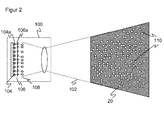
- FIG. 2 shows a schematic sectional view of the illumination unit 100 with a three-dimensional view of the projection plane of the resulting illumination pattern 20.
- the illumination unit 100 includes a light source 104, which is formed with a plurality of matrix-like arranged individual emitters 104a. For example, a two-dimensional VCSEL array is used for this purpose.
- a two-dimensional VCSEL array is used for this purpose.
- From the matrix arrangement of the individual emitter 104a only one line can be seen.
- the individual emitters 104a are regularly arranged in a conventional, commercially available VCSEL array.
- the resulting illumination pattern 20 should be irregular, stochastically distributed orsunä Siemens. Therefore, the light source 104 is preceded by a micro-optics array 106 having a plurality of micro-optics 106a.
- the micro-optics 106a are prisms shown purely schematically in this embodiment. An irregular arrangement of the micro-optics 106a results in different deflection directions for the respectively assigned individual emitters 104a. It is also conceivable to design the prisms alternatively or additionally with each other differently, so that they cause a different deflection even with the same relative position relative to the associated individual emitter 104a. Instead of prisms other non-imaging micro-optics can be used, for example by using a transmissive grating.
- the micro-optics array 106 formed as a prism field generates stochastically offset virtual dot images for each individual emitter 104a FIG. 2 are represented schematically by dot symbols 108.
- the dot symbols 108 therefore form an uneven line.
- the stochastic offset however, quite analogously also concerns the direction perpendicular to the paper plane.
- each pattern element 110 corresponds to a single emitter 104a whose transmission beam has been deflected by the non-imaging micro-optics array 106 from the originally regular arrangement. Therefore, the pattern elements 110 in their entirety form an irregular illumination pattern 20, which also imposes the structure required on a structureless scene and prevents the recognition of fake correspondences by a stereo algorithm. As an alternative to a stereo algorithm, the change in the expected structure of the illumination pattern 20 can be evaluated by objects in the scene.
- the individual emitters 104a can be operated with the same optical output power. Then, the individual pattern elements are equally bright among one another. In an advantageous development, however, this is purposefully deviated from, for example by the individual emitters 104a being driven with different currents. This can be achieved by the individual emitters 104a are individually controllable. Another possibility, in which worked with a uniform voltage and can be dispensed with an individual control, different designs of the individual emitter 104a, about different resistances in the leads by different line thicknesses or the like. This partial areas of the illumination pattern 20 are selectively lightened or darkened.
- the illumination pattern 20 can be changed in different variants of the 3D camera 10 by replacing the micro-optics array 106. Adaptability without conversion of the 3D camera 10 is possible by an advantageous development in which the individual emitters 104a are divided into two or even more groups. The groups can be controlled individually, so that their respective individual emitters 104a are selectively active or inactive, or have different brightness. In this way, different illumination patterns 20 can be generated with the same illumination unit 100 in order to adapt to applications, 3D cameras or sceneries. If a larger number of such groups is formed, the combinatorics of simultaneously active groups offers manifold possibilities of variation. In the limiting case, the individual emitters 104a are even individually controllable. It is then possible to choose the general packing density of the individual emitters 104a slightly higher than in embodiments without such groups, so that even if some groups are not active, the illumination pattern 20 still has the required degree of filling.
- the semiconductor array 104 it is conceivable to arrange the semiconductor array 104 so as to be displaceable relative to the imaging optics 108. By appropriate adjustment, a portion of the semiconductor array 104 is then selected, which is projected as illumination pattern 20. Also in this way an adjustment can be made.
Landscapes
- Engineering & Computer Science (AREA)
- Multimedia (AREA)
- Signal Processing (AREA)
- Physics & Mathematics (AREA)
- Electromagnetism (AREA)
- Length Measuring Devices By Optical Means (AREA)
- Testing, Inspecting, Measuring Of Stereoscopic Televisions And Televisions (AREA)
Abstract
Description
Die Erfindung betrifft eine 3D-Kamera mit einer Beleuchtungseinheit und ein Verfahren zur Überwachung eines Raumbereichs nach dem Oberbegriff von Anspruch 1 beziehungsweise 15.The invention relates to a 3D camera with a lighting unit and to a method for monitoring a spatial area according to the preamble of claims 1 and 15, respectively.
Im Gegensatz zu einer herkömmlichen Kamera nimmt eine 3D-Kamera auch eine Tiefeninformation auf und erzeugt somit dreidimensionale Bilddaten, die auch als Entfernungsbild oder Tiefenkarte bezeichnet werden. Die zusätzliche Entfernungsdimension lässt sich in einer Vielzahl von Anwendungen nutzen, um mehr Informationen über Objekte in der von der Kamera erfassten Szenerie zu gewinnen.In contrast to a conventional camera, a 3D camera also records depth information and thus generates three-dimensional image data, which is also referred to as a distance image or depth map. The extra range dimension can be used in a variety of applications to gain more information about objects in the scene captured by the camera.
Ein Beispiel dafür ist die Sicherheitstechnik. Eine typische sicherheitstechnische Anwendung ist die Absicherung einer gefährlichen Maschine, wie etwa einer Presse oder eines Roboters, wo bei Eingriff eines Körperteils in einen Gefahrenbereich um die Maschine herum eine Absicherung erfolgt. Dies kann je nach Situation die Abschaltung der Maschine oder das Verbringen in eine sichere Position sein. Mit der zusätzlichen Tiefeninformation lassen sich dreidimensionale Schutzbereiche definieren, die genauer an die Gefahrensituation anpassbar sind als zweidimensionale Schutzfelder, und es kann auch besser beurteilt werden, ob sich eine Person in kritischer Weise an die Gefahrenquelle annähert.An example of this is the safety technology. A typical safety application is the protection of a dangerous machine, such as a press or a robot, where protection is provided when a body part is engaged in a hazardous area around the machine. Depending on the situation, this can be the shutdown of the machine or the move to a safe position. With the additional depth information, three-dimensional protection areas can be defined which are more precisely adaptable to the danger situation than two-dimensional protection fields, and it can also be better assessed whether a person approaches the danger source in a critical manner.
In einer weiteren Anwendung werden erfasste Bewegungen als Befehl an eine mit der 3D-Kamera verbundene Steuerung interpretiert. Dazu werden beispielsweise Gesten erfasst. Obwohl dies in erster Linie aus der Unterhaltungselektronik bekannt ist, kann es auch genutzt werden, um einen Sensor in der Sicherheitstechnik zu bedienen oder zu konfigurieren, wie etwa in der
Ein bekanntes Prinzip zur Erfassung dreidimensionaler Bilddaten beruht auf Triangulation unter Zuhilfenahme einer aktiven Musterbeleuchtung. Bei stereoskopischen Systemen werden dann jeweils mindestens zwei Aufnahmen aus unterschiedlicher Perspektive erzeugt. In den überlappenden Bildbereichen werden gleiche Strukturen identifiziert und aus der Disparität und den optischen Parametern des Kamerasystems mittels Triangulation Entfernungen und somit das dreidimensionale Bild beziehungsweise die Tiefenkarte berechnet.A well-known principle for the acquisition of three-dimensional image data is based on triangulation with the aid of an active pattern illumination. In stereoscopic systems, at least two images are then generated from different perspectives. In the overlapping image areas, the same structures are identified and calculated from the disparity and the optical parameters of the camera system by means of triangulation distances and thus the three-dimensional image or the depth map.
Eine Stereokamera ist prinzipiell auch in der Lage, passiv zu arbeiten, d.h. ohne eine eigene Musterbeleuchtung. Für eine zuverlässige Bildauswertung, ganz besonders im Rahmen der Sicherheitstechnik, besteht aber der Anspruch, die dreidimensionalen Bilddaten in Form einer dichten Tiefenkarte zu erzeugen, also einen zuverlässigen Abstandswert für jeden auszuwertenden Bildbereich und bevorzugt nahezu jeden Bildpunkt verfügbar zu haben. Ist die zu überwachende Szenerie kontrastschwach oder weist Bereiche mit wenig Struktur auf, so wird dies mit einem passiven Sensor nicht erreicht. Große strukturlose Flächen oder zueinander ähnliche Strukturmerkmale können eine eindeutige Zuordnung von Bildbereichen beim Auffinden der Korrespondenzen zwischen den Strukturelementen der Bilder verhindern. Die Folge sind Lücken in den dreidimensionalen Bildern oder fehlerhafte Berechnungen der Entfernungen.A stereo camera is in principle also able to work passively, i. without a custom pattern lighting. For a reliable image analysis, especially in the context of security technology, but there is the demand to generate the three-dimensional image data in the form of a dense depth map, so a reliable distance value for each evaluated image area and preferably almost every pixel available. If the scene to be monitored is low-contrast or has areas with little structure, this is not achieved with a passive sensor. Large structureless areas or structure features similar to one another can prevent an unambiguous assignment of image areas when locating the correspondences between the structural elements of the images. The result is gaps in the three-dimensional images or erroneous calculations of the distances.
Andere Triangulationssysteme verwenden nur eine Kamera und werten die Veränderungen des projizierten Musters durch Objekte in verschiedenen Entfernungen aus. Dazu wird dem System das Beleuchtungsmuster eingelernt und so eine Erwartungshaltung für die Bilddaten bei verschiedenen Objektentfernungen und -strukturen generiert. Eine Möglichkeit besteht darin, das Beleuchtungsmuster auf Objekten, insbesondere einer Fläche, in verschiedenen Entfernungen als Referenzbild einzulernen. In einem derartigen System ist eine aktive Beleuchtung von vorne herein unverzichtbar.Other triangulation systems use only one camera and evaluate the changes in the projected pattern by objects at different distances. For this purpose, the system acquires the illumination pattern and thus generates an expectation for the image data at different object distances and structures. One possibility is to train the illumination pattern on objects, in particular a surface, at different distances as a reference image. In such a system, active lighting is indispensable from the outset.
Aus der
In der
In der
Die Verwendung von Beleuchtungseinheiten auf Basis diffraktiver optischer Elemente hat aber den weiteren Nachteil, dass die dafür als Leuchtmittel erforderlichen Singlemode-Laserdioden mit sehr kleiner Emitterfläche nur mit relativ geringer Ausgangsleistung deutlich unterhalb einem Watt verfügbar sind und nur eine begrenzte Lebensdauer haben. Dies wirkt sich nachteilig auf den Sichtbereich oder Bildfeldwinkel, die Reichweite, die Belichtungszeit und die Detektionsfähigkeit beziehungsweise Verfügbarkeit aus. Damit sind derartige Beleuchtungseinheiten gerade zur Beleuchtung größerer Bereiche in größeren Entfernungen, wie sie bei Anwendungen in der Sicherheitstechnik erforderlich sind, nur eingeschränkt verwendbar.However, the use of lighting units based on diffractive optical elements has the further disadvantage that the singlemode laser diodes with a very small emitter area required for this purpose are only available with a relatively low output power well below one watt and have only a limited service life. This adversely affects the field of view or field of view angle, the range, the exposure time and the detection capability or availability. Thus, such lighting units are just limited to the illumination of larger areas at greater distances, as required in applications in safety technology, only limited use.
In einem anderen bekannten Ansatz, der beispielsweise in der
Gemäß
Es ist daher Aufgabe der Erfindung, die Erzeugung eines Beleuchtungsmusters für eine 3D-Kamera zu verbessern.It is therefore an object of the invention to improve the generation of a lighting pattern for a 3D camera.
Diese Aufgabe wird durch eine 3D-Kamera und ein Verfahren zur Überwachung eines Raumbereichs nach Anspruch 1 beziehungsweise 15 gelöst. Dabei geht die Erfindung von dem Grundgedanken aus, das Licht einer Beleuchtungseinheit mit Hilfe einer Vielzahl von Mikrooptiken umzuverteilen, um dadurch ein unregelmäßiges Beleuchtungsmuster zu erzielen. Um die einleitend beschriebenen Nachteile bei Verwendung von Mikrolinsen zu vermeiden, werden dann erfindungsgemäß nicht abbildende Mikrooptiken verwendet, um die erforderliche unregelmäßige Struktur des Beleuchtungsmusters zu erreichen. Jedes einer Vielzahl von Einzelemittern der Beleuchtungseinheit erzeugt einen Einzellichtstrahl, der durch Ablenken an einer zugehörigen Mikrooptik ein lateral versetztes virtuelles Bild des Einzelemitters und bei Auftreffen auf ein Objekt in der Szenerie ein Musterelement bildet.This object is achieved by a 3D camera and a method for monitoring a spatial area according to claim 1 or 15. The invention is based on the basic idea of redistributing the light of a lighting unit with the aid of a multiplicity of micro-optics in order to thereby achieve an irregular lighting pattern. In order to avoid the disadvantages described in the introduction when using microlenses, non-imaging micro-optics are then used according to the invention in order to achieve the required irregular structure of the illumination pattern. Each of a plurality of individual emitters of the illumination unit generates a single-light beam which, by deflecting at an associated micro-optics, forms a laterally displaced virtual image of the single emitter and upon encountering an object in the scene a pattern element.
Dabei wird unter einer unregelmäßigen Struktur oder einer unregelmäßigen Anordnung von Musterelementen eine solche verstanden, die keine oder zumindest möglichst wenige Scheinkorrelationen bei der Bildauswertung verursacht. Im Idealfall ist die Anordnung und damit das Beleuchtungsmuster selbstunähnlich, kann also zumindest lokal innerhalb der relevanten Korrelationsfenster nicht durch einfache Symmetrieoperationen wie Translationen oder Drehungen in sich selbst überführt werden. Bei Stereokameras sind hier in erster Linie Translationen parallel zu der Stereobasis relevant, also der Verbindungsachse der Projektionszentren beider Kameras.In this case, an irregular structure or an irregular arrangement of pattern elements is understood to be one which does not cause any or at least as few apparent correlations in the image evaluation. Ideally, the arrangement and thus the illumination pattern is self-similar, so it can not be converted into itself at least locally within the relevant correlation window by simple symmetry operations such as translations or rotations. In stereo cameras, translations are primarily relevant here parallel to the stereo base, ie the connecting axis of the projection centers of both cameras.
Die Erfindung hat den Vorteil, dass Beleuchtungsmuster unter optimaler Lichtausbeute mit besonders hoher optischer Ausgangsleistung bei hoher Effizienz erzeugt werden können. Zugleich besteht eine hohe Flexibilität bei der Wahl des Beleuchtungsmusters oder konkret der Punktanordnung der in der Szenerie auftreffenden Einzellichtstrahlen der Einzelemitter. Mit derselben Lichtquelle entstehen mittels unterschiedlicher Mikrooptikarrays unterschiedliche Beleuchtungsmuster, beispielsweise für unterschiedliche Reichweitenvarianten der 3D-Kamera. Ein Mikrooptikarray ist verhältnismäßig einfach herzustellen.The invention has the advantage that illumination patterns can be generated under optimal light output with a particularly high optical output power with high efficiency. At the same time there is a high degree of flexibility in the choice of the illumination pattern or specifically, the point arrangement of the incident in the scenery single light beams of the individual emitter. With the same light source different illumination patterns are created by means of different micro-optic arrays, for example for different range variants of the 3D camera. A micro-optic array is relatively easy to manufacture.
Das Mikrooptikarray ist bevorzugt ein Mikroprismenarray, wobei die nichtabbildenden Mikrooptiken als Prismen ausgebildet sind, welche die Lichtstrahlen der Einzelemitter jeweils in unterschiedliche Richtungen ablenken. Derartige Mikroprismenfelder können sehr einfach durch ein Prägeverfahren hergestellt werden. Durch die Prismen werden die Strahlkeulen der Einzelstrahlen der Einzelemitter separat abgelenkt.The micro-optics array is preferably a micro-prism array, wherein the non-imaging micro-optics are formed as prisms, which deflect the light beams of the individual emitter respectively in different directions. Such microprism fields can be very easily produced by a stamping process. The prisms deflect the beam lobes of the individual beams of the individual emitters separately.
Die Prismen weisen bevorzugt eine Fresnelstruktur aus. Damit kann durch Strukturierung der Prismen die Geometrie des Mikroprismenfeldes beeinflusst, beispielsweise eine Dicke reduziert werden.The prisms preferably have a Fresnel structure. This can be influenced by structuring the prisms, the geometry of the micro-prism field, for example, a thickness can be reduced.
Die Prismen sind bevorzugt untereinander unterschiedlich ausgebildet und transmittieren somit einfallende Lichtstrahlen in unterschiedlichen Ablenkwinkeln. Damit entsteht eine größere Freiheit, das resultierende Beleuchtungsmuster zu gestalten, und die Struktur des Beleuchtungsmusters hängt nicht allein von der Anordnung der Prismen innerhalb des Mikrooptikarrays ab. Werden alternativ Prismen mit gleichmäßigen Ablenkwinkeln verwendet, so müssen die Prismen zwingend irregulär auf dem Mikrooptikarray angeordnet werden, um ein unregelmäßiges Beleuchtungsmuster zu erreichen.The prisms are preferably formed differently with each other and thus transmit incident light beams in different deflection angles. This results in greater freedom to design the resulting illumination pattern, and the structure of the illumination pattern does not depend solely on the arrangement of the prisms within the micro-optics array. Alternatively, if prisms with uniform deflection angles are used, the prisms must imperatively be arranged irregularly on the micro-optics array in order to achieve an irregular illumination pattern.
Die Mikrooptiken sind bevorzugt unregelmäßig angeordnet. Wie soeben beschrieben, könnte die Unregelmäßigkeit des Beleuchtungsmusters auch allein durch unterschiedliche Ablenkwinkel der einzelnen Mikrooptiken erzielt werden. Durch eine unregelmäßige Anordnung gibt es aber zusätzliche Stellschrauben für die Struktur des Beleuchtungsmusters.The micro-optics are preferably arranged irregularly. As just described, the irregularity of the illumination pattern could also be achieved solely by different deflection angles of the individual micro-optics. Due to an irregular arrangement, however, there are additional adjustment screws for the structure of the illumination pattern.
Die Einzelemitter sind in einer alternativen Ausführungsform unregelmäßig angeordnet. Ein solches Emitterarray ist im Vergleich zu einem unregelmäßigen Mikrooptikarray aufwändig herzustellen. Es gibt dann insgesamt drei verschiedene Ansatzpunkte, ein unregelmäßiges Beleuchtungsmuster zu erzeugen: die Anordnung der Einzelemitter, die Anordnung der Mikrooptiken und die Ausgestaltung der einzelnen Mikrooptiken, insbesondere deren Ablenkwinkel. Diese drei Variationsmöglichkeiten können einzeln oder in Kombination eingesetzt werden.The individual emitters are arranged irregularly in an alternative embodiment. Such an emitter array is complex to produce compared to an irregular micro-optic array. There are then three different starting points for generating an irregular illumination pattern: the arrangement of the individual emitters, the arrangement of the micro-optics and the design of the individual micro-optics, in particular their deflection angle. These three variations can be used individually or in combination.
Das Halbleiterarray ist bevorzugt ein VCSEL-Array (Vertical-Cavity Surface-Emitting Laser). Durch eine unregelmäßige Maske für die Emitterflächen wird die gewünschte Anordnung der Einzelemitter des VCSEL-Arrays erreicht. Da aufgrund der erfindungsgemäßen Anordnung von der ursprünglichen Ausgangsleistung kaum etwas verloren geht, genügen VCSEL-Arrays mit moderaten Gesamtleistungen von einigen Watt, wobei natürlich auch VSCEL-Arrays mit höheren Leistungen insbesondere für sehr große Reichweiten eingesetzt werden können.The semiconductor array is preferably a VCSEL array (Vertical-Cavity Surface-Emitting Laser). An irregular mask for the emitter surfaces achieves the desired arrangement of the individual emitters of the VCSEL array. Since hardly anything is lost due to the arrangement according to the invention from the original output power, VCSEL arrays with moderate total powers of a few watts are sufficient, whereby naturally also VSCEL arrays with higher powers can be used in particular for very long ranges.
Das Halbleiterarray weist bevorzugt eine große Anzahl von mindestens tausend, zehntausend oder hunderttausend Einzelemittern auf. Solche Halbleiterarrays sind beispielsweise in Form von VCSEL-Arrays vergleichsweise kostengünstig erhältlich. Die große Anzahl an Einzelemittern mit einer entsprechend hohen Anzahl von Musterelementen in dem Beleuchtungsmuster führt zu einem Beleuchtungsmuster mit hinreichend feiner Struktur, um eine hohe Auflösung der 3D-Kamera zu gewährleisten.The semiconductor array preferably has a large number of at least a thousand, ten thousand or one hundred thousand individual emitters. Such semiconductor arrays are available comparatively inexpensively, for example in the form of VCSEL arrays. The large number of individual emitters with a correspondingly high number of pattern elements in the illumination pattern leads to a lighting pattern with a sufficiently fine structure to ensure a high resolution of the 3D camera.
Jeder Einzelemitter weist bevorzugt eine punktförmige Abstrahlfläche und das von dem Einzelemitter erzeugte Musterelement die Form der Abstrahlfläche auf. Damit entsteht ein Punktmuster, bei dem jedes Musterelement ein von einem Einzelemitter erzeugter Punkt ist, wobei dies natürlich nicht im strengen geometrischen Sinne als dimensionslos zu verstehen ist. Der Punkt hat eine gewisse endliche Ausdehnung und soll dies auch haben, um von dem Bildsensor erfasst zu werden.Each individual emitter preferably has a punctiform radiating surface and the pattern element produced by the individual emitter has the shape of the radiating surface. This results in a dot pattern in which each pattern element is a point generated by a single emitter, which of course is not to be understood in the strict geometric sense as dimensionless. The point has some finite extent and is supposed to have this to be detected by the image sensor.
Die Einzelemitter bilden bevorzugt mindestens zwei Gruppen, wobei eine Gruppe von Einzelemittern aktivierbar ist, ohne die übrigen Gruppen von Einzelemittern zu aktivieren. Damit kann zwischen verschiedenen Mustern umgeschaltet werden, die durch jeweils eine Gruppe oder eine Kombination mehrerer Gruppen entstehen. Im Grenzfall bildet jeder Einzelemitter eine eigene Gruppe und ist damit selektiv aktivierbar. Bildet man das Halbleiterarray mit einer höheren Packungsdichte von Einzelemittern aus, als für die Beleuchtung erforderlich ist, so bewirkt auch die Aktivierung von Teilmengen eine ausreichende Beleuchtung. Durch gezielte Auswahl solcher Teilmengen oder Gruppenkombinationen wird dann eine adaptive Anpassung des Beleuchtungsmusters an die gegebene Szenerie ermöglicht.The individual emitters preferably form at least two groups, wherein a group of individual emitters can be activated without activating the remaining groups of individual emitters. This can be used to switch between different patterns, each resulting from a group or a combination of several groups. In the limiting case, each individual emitter forms its own group and can thus be selectively activated. If the semiconductor array is formed with a higher packing density of single emitters than is required for the illumination, the activation of subsets also causes sufficient illumination. By selectively selecting such subsets or group combinations, an adaptive adaptation of the illumination pattern to the given scene is then enabled.
Die Einzelemitter sind bevorzugt mit untereinander unterschiedlichen Strömen ansteuerbar. Das lässt sich beispielsweise durch unterschiedliche Widerstände beziehungsweise Dicken der Zuleitungen erreichen. Die einzelnen Musterelemente werden durch den derart eingeführten Leistungsgradienten unterschiedlich hell. Auch das kann zur Adaption an eine Szenerie ausgenutzt werden. Ein Fall von allgemeinerem Interesse ist die Kompensation des Randabfalls. Das ist ein nachteiliger Effekt von Optiken beziehungsweise Bildsensoren, die zu ungleichmäßig beleuchteten Bildern mit dunkleren Rändern führen. Dies wird ausgeglichen, indem vorzugsweise die Einzelemitter in einem Außenbereich des Halbleiterarrays mit höheren Strömen ansteuerbar sind als Einzelemitter in einem Innenbereich des Halbleiterarrays. Somit kann über die Wahl der Elektrode auf dem Halbleiterarray der Lichtquelle und Einstellung des lokalen Stromflusses die lokale Helligkeitsverteilung des Beleuchtungsmusters angepasst und damit auch auf eine separate Homogenisierung der Helligkeit verzichtet werden.The individual emitters are preferably controllable with mutually different currents. This can be achieved, for example, by different resistances or thicknesses of the supply lines. The individual pattern elements are differently bright due to the power gradient introduced in this way. This, too, can be exploited for adaptation to a scene. A case of more general interest is the compensation of edge drop. This is a detrimental effect of optics or image sensors that result in unevenly illuminated images with darker edges. This is compensated by preferably the individual emitters in an outer region of the semiconductor array can be driven with higher currents than individual emitters in an inner region of the semiconductor array. Thus, the choice of the electrode on the semiconductor array of the light source and adjustment of the local current flow, the local brightness distribution of the illumination pattern adapted and thus dispense with a separate homogenization of the brightness.
Die Beleuchtungseinheit weist bevorzugt ein Abbildungsobjektiv auf, um das Beleuchtungsmuster in den Raumbereich zu projizieren. Als Abbildungsobjektiv genügt im einfachsten Fall eine einzige Linse. Das Abbildungsobjektiv kann aber auch reflexiv statt refraktiv ausgebildet sein. Die Einzelemitter müssen dank des Abbildungsobjektivs das Musterelement nicht im Fernfeld des Raumbereichs erzeugen, sondern das Muster wird schon kurz hinter dem Mustererzeugungselement abgegriffen und in den Raumbereich projiziert. Das Abbildungsobjektiv gleicht die Divergenz der Einzelemitter aus, die mit geringerer Abstrahlfläche zunimmt.The illumination unit preferably has an imaging objective in order to project the illumination pattern into the spatial area. As an imaging lens is sufficient in the simplest case, a single lens. The imaging lens can also be designed to be reflective rather than refractive. Thanks to the imaging lens, the individual emitters do not have to generate the pattern element in the far field of the spatial region, but the pattern is tapped shortly after the pattern generation element and projected into the spatial region. The imaging lens compensates for the divergence of the individual emitters, which increases with less radiation area.
Abbildungsobjektiv und Halbleiterarray sind vorzugsweise zueinander verschieblich angeordnet, um unterschiedliche Teilmengen von Einzelemittern abzubilden. Es wird dabei jeweils ein anderer Bereich des Halbleiterarrays ausgenutzt, um das Beleuchtungsmuster zu erzeugen, um so eine Anpassung an die Szenerie zu ermöglichen.The imaging objective and the semiconductor array are preferably arranged displaceably relative to one another in order to image different subsets of individual emitters. In each case, a different area of the semiconductor array is used to generate the illumination pattern so as to allow an adaptation to the scene.
Die 3D-Kamera ist bevorzugt als Stereokamera ausgebildet, wobei die Auswertungseinheit eine Stereoskopieauswertungseinheit aufweist, welche für die Anwendung eines Stereoalgorithmus ausgebildet ist, in dem zur Erzeugung eines dreidimensionalen Entfernungsbildes einander zugehörige Teilbereiche der von den beiden Kameras der Stereokamera aufgenommenen Bilder des von dem Beleuchtungsmuster ausgeleuchteten Raumbereichs erkannt und deren Entfernung anhand der Disparität berechnet wird. Der erfindungsgemäß erhöhte Kontrast in der Szenerie hilft dabei, auch bei einer ungünstigen Szenerie dichte Tiefenkarten zu erfassen.The 3D camera is preferably designed as a stereo camera, wherein the evaluation unit has a Stereoskopieauswertungseinheit, which is designed for generating a three-dimensional distance image associated partial areas of the two cameras of the stereo camera images of the illuminated from the illumination pattern Spaces are recognized and their distance is calculated on the basis of the disparity. The inventively increased contrast in the scenery helps to capture dense depth maps even in an unfavorable scenery.
Die 3D-Kamera ist bevorzugt als Sicherheitskamera ausgebildet, wobei die Auswertungseinheit dafür ausgebildet ist, unzulässige Eingriffe in den Raumbereich zu erkennen und daraufhin ein Abschaltsignal zu erzeugen, und wobei ein Sicherheitsausgang vorgesehen ist, um darüber ein Abschaltsignal an eine überwachte Maschine auszugeben. Gerade für sicherheitstechnische Anwendungen ist eine zuverlässige Erfassung einer dichten Tiefenkarte erforderlich. Dadurch wird die erforderliche sichere Objektdetektion ermöglicht.The 3D camera is preferably designed as a security camera, wherein the evaluation unit is designed to detect impermissible interventions in the spatial area and then to generate a shutdown signal, and wherein a safety output is provided in order to output a shutdown signal to a monitored machine. Especially for safety applications reliable detection of a dense depth map is required. This allows the required safe object detection.
Das erfindungsgemäße Verfahren kann auf ähnliche Weise weitergebildet werden und zeigt dabei ähnliche Vorteile. Derartige vorteilhafte Merkmale sind beispielhaft, aber nicht abschließend in den sich an die unabhängigen Ansprüche anschließenden Unteransprüchen beschrieben.The method according to the invention can be developed in a similar manner and shows similar advantages. Such advantageous features are described by way of example but not exhaustively in the subclaims following the independent claims.
Die Erfindung wird nachstehend auch hinsichtlich weiterer Merkmale und Vorteile beispielhaft anhand von Ausführungsformen und unter Bezug auf die beigefügte Zeichnung näher erläutert. Die Abbildungen der Zeichnung zeigen in:
- Fig. 1
- eine schematische Gesamtdarstellung einer Ausführungsform einer erfindungsgemäßen 3D-Kamera mit dem von deren Beleuchtungseinheit ausgeleuchteten Raumbereich; und
- Fig. 2
- eine schematische Schnittansicht der Beleuchtungseinheit der 3D-Kamera gemäß
Figur 1 mit einer dreidimensionalen Ansicht der Projektionsebene des entstehenden Beleuchtungsmusters.
- Fig. 1
- a schematic overall view of an embodiment of a 3D camera according to the invention with the area illuminated by the illumination unit of the space; and
- Fig. 2
- a schematic sectional view of the illumination unit of the 3D camera according to
FIG. 1 with a three-dimensional view of the projection plane of the resulting illumination pattern.
In der 3D-Kamera 10 sind zwei Kameramodule in einem bekannten festen Abstand zueinander montiert und nehmen jeweils Bilder des Raumbereichs12 auf. In jeder Kamera ist ein Bildsensor 14a, 14b vorgesehen, üblicherweise ein matrixförmiger Aufnahmechip, der ein rechteckiges Pixelbild aufnimmt, beispielsweise ein CCD- oder ein CMOS-Sensor. Den Bildsensoren 14a, 14b ist jeweils ein Objektiv mit einer abbildenden Optik zugeordnet, welches als Linse 16a, 16b dargestellt ist und in der Praxis als jede bekannte Abbildungsoptik realisiert sein kann. Der Sichtwinkel dieser Optiken ist in
In der Mitte zwischen den beiden Bildsensoren 14a, 14b ist eine Beleuchtungseinheit 100 dargestellt, wobei diese räumliche Anordnung nur als Beispiel zu verstehen ist und die Beleuchtungseinheit ebenso asymmetrisch oder sogar außerhalb der 3D-Kamera 10 angeordnet sein kann. Die Beleuchtungseinheit 100 erzeugt in einem Beleuchtungsbereich 102 ein strukturiertes Beleuchtungsmuster 20 und wird weiter unten im Zusammenhang mit
Mit den beiden Bildsensoren 14a, 14b und der Beleuchtungseinheit 100 ist eine kombinierte Auswertungs- und Steuerungseinheit 22 verbunden. Mittels der Steuerung 22 wird das strukturierte Beleuchtungsmuster 20 erzeugt und bei Bedarf in seiner Struktur oder Intensität variiert, und die Steuerung 22 empfängt Bilddaten der Bildsensoren 14a, 14b. Aus diesen Bilddaten berechnet eine Stereoskopieauswertungseinheit 24 der Steuerung 22 mit Hilfe einer stereoskopischen Disparitätsschätzung dreidimensionale Bilddaten (Entfernungsbild, Tiefenkarte) des Raumbereichs 12. Das strukturierte Beleuchtungsmuster 20 sorgt dabei für einen guten Kontrast und eine eindeutig zuordenbare Struktur jedes Bildelements in dem beleuchteten Raumbereich 12.A combined evaluation and
Erkennt die Steuerung 22 weiterhin einen unzulässigen Eingriff in einen Schutzbereich, so wird eine Warnung ausgegeben oder eine Gefahrenquelle abgesichert, beispielsweise ein Roboterarm oder eine sonstige Maschine gestoppt. Sicherheitsrelevante Signale, also vor allem das Abschaltsignal, werden über einen Sicherheitsausgang 26 ausgegeben (OSSD, Output Signal Switching Device). In nichtsicherheitstechnischen Anwendungen kann auf diese Funktionalität auch verzichtet werden. Ebenso ist denkbar, dass die dreidimensionalen Bilddaten lediglich als solche ausgegeben und weitere Auswertungen extern vorgenommen werden.If the
Um für sicherheitstechnische Anwendungen geeignet zu sein, ist die 3D-Kamera 10 fehlersicher ausgelegt. Dies bedeutet unter anderem, dass die 3D-Kamera 10 sich selber in Zyklen unterhalb der geforderten Ansprechzeit testen kann, insbesondere auch Defekte der Beleuchtungseinheit 100 erkennt und somit sicherstellt, dass das Beleuchtungsmuster 20 in einer erwarteten Mindestintensität verfügbar ist, und dass der Sicherheitsausgang 26 sicher, beispielsweise zweikanalig ausgelegt ist. Ebenso ist auch die Steuerung 22 mit der Stereoskopieeinheit 24 selbstsicher, wertet also zweikanalig aus oder verwendet Algorithmen, die sich selbst prüfen können. Derartige Vorschriften sind für allgemeine berührungslos wirkende Schutzeinrichtungen beispielsweise in der EN 61496-1 bzw. der EN 13849-1 normiert. Eine entsprechende Norm für Sicherheitskameras befindet sich in der Vorbereitung.In order to be suitable for safety applications, the
Die Einzelemitter 104a sind bei einem üblichen, kommerziell erhältlichen VCSEL-Array regelmäßig angeordnet. Das entstehende Beleuchtungsmuster 20 soll aber unregelmäßig, stochastisch verteilt beziehungsweise selbstunähnlich sein. Deshalb ist der Lichtquelle 104 ein Mikrooptikarray 106 mit einer Vielzahl von Mikrooptiken 106a vorgeordnet.The
Die Mikrooptiken 106a sind in dieser Ausführungsform rein schematisch dargestellte Prismen. Durch eine unregelmäßige Anordnung der Mikrooptiken 106a entstehen unterschiedliche Ablenkungsrichtungen für die jeweils zugeordneten Einzelemitter 104a. Es ist auch denkbar, die Prismen alternativ oder zusätzlich untereinander unterschiedlich zu gestalten, so dass sie auch bei gleicher relativer Lage gegenüber dem zugeordneten Einzelemitter 104a eine unterschiedliche Ablenkung bewirken. Anstelle von Prismen können auch andere nicht abbildende Mikrooptiken eingesetzt werden, beispielsweise durch Verwendung eines transmissiven Gitters.The
Wegen der unterschiedlichen Ablenkungsrichtungen erzeugt das als Prismenfeld ausgebildete Mikrooptikarray 106 für jeden Einzelemitter 104a stochastisch versetzte virtuelle Punktbilder, die in
Mit Hilfe eines Abbildungsobjektivs 108 wird das Beleuchtungsmuster 20 in den Raumbereich 12 projiziert. Das Abbildungsobjektiv 108 ist im einfachsten Fall eine Sammellinse, kann aber in an sich bekannter Weise auch andere oder mehrere optische Elemente aufweisen. In dem Beleuchtungsmuster 20 entspricht jedes Musterelement 110 einem Einzelemitter 104a, dessen Sendestrahl durch das nicht abbildende Mikrooptikarray 106 aus der ursprünglich regelmäßigen Anordnung abgelenkt wurde. Deshalb bilden die Musterelemente 110 in ihrer Gesamtheit ein unregelmäßiges Beleuchtungsmuster 20, das auch einer strukturlosen Szenerie die erforderliche Struktur aufprägt und die Erkennung von Scheinkorrespondenzen durch einen Stereoalgorithmus verhindert. Alternativ zu einem Stereoalgorithmus kann die Veränderung der erwarteten Struktur des Beleuchtungsmusters 20 durch Objekte in der Szenerie ausgewertet werden.With the aid of an
Die Einzelemitter 104a können mit gleicher optischer Ausgangsleistung betrieben werden. Dann sind die einzelnen Musterelemente untereinander gleich hell. In einer vorteilhaften Weiterbildung wird davon aber gezielt abgewichen, beispielsweise indem die Einzelemitter 104a mit unterschiedlichen Strömen angesteuert werden. Dies lässt sich erreichen, indem die Einzelemitter 104a einzeln ansteuerbar sind. Eine andere Möglichkeit, bei der mit einer einheitlichen Spannung gearbeitet und auf eine individuelle Ansteuerung verzichtet werden kann, sind unterschiedliche Designs der Einzelemitter 104a, etwa unterschiedliche Widerstände in den Zuleitungen durch unterschiedliche Leitungsdicken oder dergleichen. Damit werden Teilbereiche des Beleuchtungsmusters 20 gezielt aufgehellt oder abgedunkelt. Eine Anwendung ist eine Randbereichsüberhöhung mit besonders hellen Rändern des Beleuchtungsmusters 20, um einen entsprechenden Randbereichsabfall der Bildsensoren 14a-b beziehungsweise der Optiken 16a-b zu kompensieren. So werden besonders homogen ausgeleuchtete Bilder aufgenommen. Dazu werden die Einzelemitter 104a in einem Außenbereich des Halbleiterarrays der Lichtquelle 104 stärker bestromt als in dessen Innerem und senden somit mehr Licht aus.The
Das Beleuchtungsmuster 20 kann in unterschiedlichen Varianten der 3D-Kamera 10 durch Austausch des Mikrooptikarrays 106 verändert werden. Eine Anpassbarkeit ohne Umbau der 3D-Kamera 10 ist durch eine vorteilhafte Weiterbildung möglich, bei welcher die Einzelemitter 104a in zwei oder noch mehr Gruppen aufgeteilt werden. Die Gruppen können dabei einzeln angesteuert werden, so dass ihre jeweiligen Einzelemitter 104a wahlweise aktiv oder inaktiv sind oder unterschiedlich hell leuchten. Damit können mit derselben Beleuchtungseinheit 100 unterschiedliche Beleuchtungsmuster 20 erzeugt werden, um sich an Anwendungen, 3D-Kameras oder Szenerien anzupassen. Wird eine größere Anzahl solcher Gruppen gebildet, so bietet die Kombinatorik gleichzeitig aktiver Gruppen vielfältige Variationsmöglichkeiten. Im Grenzfall sind die Einzelemitter 104a sogar einzeln ansteuerbar. Man kann dann die allgemeine Packungsdichte der Einzelemitter 104a etwas höher wählen als bei Ausführungsformen ohne solche Gruppen, damit auch dann, wenn einige Gruppen nicht aktiv sind, das Beleuchtungsmuster 20 noch den erforderlichen Füllgrad aufweist.The
Weiterhin ist denkbar, das Halbleiterarray 104 gegenüber der Abbildungsoptik 108 verschieblich anzuordnen. Durch entsprechende Justage wird dann ein Teilbereich des Halbleiterarrays 104 ausgewählt, der als Beleuchtungsmuster 20 projiziert wird. Auch auf diese Weise kann eine Anpassung erfolgen.Furthermore, it is conceivable to arrange the
Claims (15)
dadurch gekennzeichnet,
dass die Lichtquelle (104) ein Halbleiterarray mit einer Vielzahl von Einzelemittern (104a) aufweist, und dass das Mikrooptikarray (106) nicht abbildende Mikrooptiken (106a) aufweist.3D camera (10) for monitoring a spatial area (12), wherein the 3D camera (10) at least one image sensor (14a-b) for receiving image data from the spatial area (10), an evaluation unit (22, 24) for generating a distance image with three-dimensional image data from the image data of the image sensor (14a-b) and a lighting unit (100) with a light source (104) and an upstream micro-optical array (106) with a multiplicity of micro-optics (106a) to form the spatial region (12) to illuminate with an irregular illumination pattern (20),
characterized,
in that the light source (104) has a semiconductor array with a plurality of individual emitters (104a), and in that the microoptical array (106) has non-imaging micro-optics (106a).
wobei das Mikrooptikarray (106) ein Mikroprismenarray ist, wobei die nichtabbildenden Mikrooptiken (106a) als Prismen ausgebildet sind, welche die Lichtstrahlen der Einzelemitter (104a) jeweils in unterschiedliche Richtungen ablenken.3D camera (10) according to claim 1,
wherein the micro-optics array (106) is a micro-prism array, wherein the non-imaging micro-optics (106a) are formed as prisms which deflect the light beams of the individual emitters (104a) in different directions, respectively.
wobei die Prismen (1 06a) eine Fresnelstruktur aufweisen.3D camera (10) according to claim 2,
wherein the prisms (1 06a) have a Fresnel structure.
wobei die Prismen (106a) untereinander unterschiedlich ausgebildet sind und somit einfallende Lichtstrahlen in unterschiedlichen Ablenkwinkeln transmittieren.3D camera (10) according to claim 2 or 3,
wherein the prisms (106a) are formed differently with each other and thus transmit incident light rays at different deflection angles.
wobei die Mikrooptiken (106a) unregelmäßig angeordnet sind.3D camera (10) according to one of the preceding claims,
wherein the micro-optics (106a) are arranged irregularly.
wobei die Einzelemitter (104a) unregelmäßig angeordnet sind.3D camera (10) according to one of the preceding claims,
wherein the individual emitters (104a) are arranged irregularly.
wobei das Halbleiterarray (104) ein VCSEL-Array ist.3D camera (10) according to one of the preceding claims,
wherein the semiconductor array (104) is a VCSEL array.
wobei jeder Einzelemitter (104a) eine punktförmige Abstrahlfläche aufweist, und wobei das von dem Einzelemitter (104a) erzeugte Musterelement die Form der Abstrahlfläche aufweist.3D camera (10) according to one of the preceding claims,
wherein each individual emitter (104a) has a point-shaped radiating surface, and wherein the pattern element produced by the single emitter (104a) has the shape of the radiating surface.
wobei Einzelemitter (1 04a) mindestens zwei Gruppen bilden, und wobei eine Gruppe von Einzelemittern (1 04a) aktivierbar ist, ohne die übrigen Gruppen von Einzelemittern (1 04a) zu aktivieren.3D camera (10) according to one of the preceding claims,
wherein individual emitter (1 04a) form at least two groups, and wherein a group of individual emitters (1 04a) can be activated without activating the remaining groups of individual emitters (1 04a).
wobei die Einzelemitter (104a) mit untereinander unterschiedlichen Strömen ansteuerbar sind, insbesondere Einzelemitter (104a) in einem Außenbereich des Halbleiterarrays (104) mit höheren Strömen ansteuerbar sind als Einzelemitter (1 04a) in einem Innenbereich des Halbleiterarrays (104).3D camera (10) according to one of the preceding claims,
wherein the individual emitters (104a) can be driven with mutually different currents, in particular individual emitters (104a) in an outer region of the semiconductor array (104) can be driven with higher currents than individual emitters (104a) in an inner region of the semiconductor array (104).
wobei die Beleuchtungseinheit (100) ein Abbildungsobjektiv (108) aufweist, um das Beleuchtungsmuster (20) in den Raumbereich (12) zu projizieren.3D camera (10) according to one of the preceding claims,
wherein the illumination unit (100) comprises an imaging lens (108) for projecting the illumination pattern (20) into the spatial area (12).
wobei Abbildungsobjektiv (108) und Halbleiterarray (104) zueinander verschieblich angeordnet sind, um unterschiedliche Teilmengen von Einzelemittern (104a) abzubilden.3D camera (10) according to one of the preceding claims,
wherein the imaging objective (108) and the semiconductor array (104) are arranged displaceably relative to one another in order to image different subsets of individual emitters (104a).
die als Stereokamera (10) ausgebildet ist, und wobei die Auswertungseinheit (22) eine Stereoskopieauswertungseinheit (24) aufweist, welche für die Anwendung eines Stereoalgorithmus ausgebildet ist, in dem zur Erzeugung eines dreidimensionalen Entfernungsbildes einander zugehörige Teilbereiche der von den beiden Kameras der Stereokamera (10) aufgenommenen Bilder des von dem Beleuchtungsmuster (20) ausgeleuchteten Raumbereichs (12) erkannt und deren Entfernung anhand der Disparität berechnet wird.3D camera according to one of the preceding claims,
which is designed as a stereo camera (10), and wherein the evaluation unit (22) has a stereoscopic evaluation unit (24) which is designed for the application of a stereo algorithm in which mutually associated partial areas of the two cameras of the stereo camera (FIG. 10) recorded images of the illuminated by the illumination pattern (20) illuminated space area (12) and whose distance is calculated on the basis of the disparity.
die als Sicherheitskamera ausgebildet ist, wobei die Auswertungseinheit (22) dafür ausgebildet ist, unzulässige Eingriffe in den Raumbereich (12) zu erkennen und daraufhin ein Abschaltsignal zu erzeugen, und wobei ein Sicherheitsausgang (26) vorgesehen ist, um darüber ein Abschaltsignal an eine überwachte Maschine auszugeben.3D camera (10) according to one of the preceding claims,
which is designed as a security camera, wherein the evaluation unit (22) is adapted to detect impermissible interventions in the spatial area (12) and then to generate a shutdown signal, and wherein a safety output (26) is provided, about a shutdown signal to a monitored Machine output.
dass von der als ein Halbleiterarray mit einer Vielzahl von Einzelemittern (104a) ausgebildeten Lichtquelle (104) eine entsprechende Anzahl von Einzellichtstrahlen ausgesandt wird, die von dem Mikrooptikarray (106) nicht abbildend in das unregelmäßige Beleuchtungsmuster (20) abgelenkt werden.A method for monitoring a spatial region (12), wherein image data is taken from the spatial region (12) and a distance image with three-dimensional image data is generated from the image data, wherein the spatial region (12) of a lighting unit (100) with a light source (104) and an upstream microoptical array (106) having a plurality of micro-optics (106a) with an irregular illumination pattern (20) is illuminated, characterized
in that a corresponding number of individual light beams, which are not deflected by the microoptical array (106) into the irregular illumination pattern (20), are emitted by the light source (104) formed as a semiconductor array with a multiplicity of individual emitters (104a).
Applications Claiming Priority (1)
| Application Number | Priority Date | Filing Date | Title |
|---|---|---|---|
| DE102011052802.4A DE102011052802B4 (en) | 2011-08-18 | 2011-08-18 | 3D camera and method for monitoring a room area |
Publications (3)
| Publication Number | Publication Date |
|---|---|
| EP2560366A2 true EP2560366A2 (en) | 2013-02-20 |
| EP2560366A3 EP2560366A3 (en) | 2013-03-06 |
| EP2560366B1 EP2560366B1 (en) | 2013-09-18 |
Family
ID=46679098
Family Applications (1)
| Application Number | Title | Priority Date | Filing Date |
|---|---|---|---|
| EP12176554.9A Not-in-force EP2560366B1 (en) | 2011-08-18 | 2012-07-16 | 3D camera and method for monitoring a room |
Country Status (3)
| Country | Link |
|---|---|
| US (1) | US20130044187A1 (en) |
| EP (1) | EP2560366B1 (en) |
| DE (1) | DE102011052802B4 (en) |
Cited By (2)
| Publication number | Priority date | Publication date | Assignee | Title |
|---|---|---|---|---|
| EP2860714A1 (en) * | 2013-10-09 | 2015-04-15 | Sick Ag | Method and optoelectronic device for monitoring of a surveillance area |
| EP3438691A1 (en) * | 2017-08-04 | 2019-02-06 | Sick AG | Optoelectronic sensor and method for detecting objects in a surveillance area |
Families Citing this family (43)
| Publication number | Priority date | Publication date | Assignee | Title |
|---|---|---|---|---|
| CN104247178B (en) * | 2012-03-01 | 2018-01-02 | Iee国际电子工程股份公司 | Space encoding structured light maker |
| US20140307055A1 (en) * | 2013-04-15 | 2014-10-16 | Microsoft Corporation | Intensity-modulated light pattern for active stereo |
| US20150260830A1 (en) * | 2013-07-12 | 2015-09-17 | Princeton Optronics Inc. | 2-D Planar VCSEL Source for 3-D Imaging |
| US9451162B2 (en) | 2013-08-21 | 2016-09-20 | Jaunt Inc. | Camera array including camera modules |
| US11019258B2 (en) | 2013-08-21 | 2021-05-25 | Verizon Patent And Licensing Inc. | Aggregating images and audio data to generate content |
| US11265534B2 (en) * | 2014-02-08 | 2022-03-01 | Microsoft Technology Licensing, Llc | Environment-dependent active illumination for stereo matching |
| US9911454B2 (en) | 2014-05-29 | 2018-03-06 | Jaunt Inc. | Camera array including camera modules |
| US10368011B2 (en) | 2014-07-25 | 2019-07-30 | Jaunt Inc. | Camera array removing lens distortion |
| US11108971B2 (en) | 2014-07-25 | 2021-08-31 | Verzon Patent and Licensing Ine. | Camera array removing lens distortion |
| US9363569B1 (en) | 2014-07-28 | 2016-06-07 | Jaunt Inc. | Virtual reality system including social graph |
| US10186301B1 (en) | 2014-07-28 | 2019-01-22 | Jaunt Inc. | Camera array including camera modules |
| US10440398B2 (en) | 2014-07-28 | 2019-10-08 | Jaunt, Inc. | Probabilistic model to compress images for three-dimensional video |
| US9774887B1 (en) | 2016-09-19 | 2017-09-26 | Jaunt Inc. | Behavioral directional encoding of three-dimensional video |
| US10701426B1 (en) | 2014-07-28 | 2020-06-30 | Verizon Patent And Licensing Inc. | Virtual reality system including social graph |
| US20160072258A1 (en) * | 2014-09-10 | 2016-03-10 | Princeton Optronics Inc. | High Resolution Structured Light Source |
| US9854227B2 (en) | 2015-01-08 | 2017-12-26 | David G Grossman | Depth sensor |
| US9553423B2 (en) * | 2015-02-27 | 2017-01-24 | Princeton Optronics Inc. | Miniature structured light illuminator |
| US11149155B2 (en) | 2015-05-01 | 2021-10-19 | Sun Chemical Corporation | Electrically-insulating energy-curable inkjet fluids |
| US10790325B2 (en) | 2015-07-29 | 2020-09-29 | Samsung Electronics Co., Ltd. | Imaging apparatus and image sensor including the same |
| KR102496374B1 (en) * | 2015-07-29 | 2023-02-06 | 삼성전자주식회사 | Image sensor |
| US11469265B2 (en) | 2015-07-29 | 2022-10-11 | Samsung Electronics Co., Ltd. | Imaging apparatus and image sensor including the same |
| US10403668B2 (en) * | 2015-07-29 | 2019-09-03 | Samsung Electronics Co., Ltd. | Imaging apparatus and image sensor including the same |
| US11089286B2 (en) | 2015-07-29 | 2021-08-10 | Samsung Electronics Co., Ltd. | Image sensor |
| US10761244B2 (en) | 2015-08-13 | 2020-09-01 | Ams Sensors Singapore Pte. Ltd. | Illumination assembly for 3D data acquisition |
| CN108027129B (en) | 2015-08-28 | 2020-05-15 | 赫普塔冈微光有限公司 | Lighting module for translating light |
| US9992477B2 (en) | 2015-09-24 | 2018-06-05 | Ouster, Inc. | Optical system for collecting distance information within a field |
| KR102597579B1 (en) | 2015-10-21 | 2023-11-01 | 프린스톤 옵트로닉스, 인크. | Coded Pattern Projector |
| AU2017212835B2 (en) * | 2016-01-29 | 2019-03-14 | Ouster, Inc. | Systems and methods for calibrating an optical distance sensor |
| DE102016109131B4 (en) * | 2016-05-18 | 2018-03-01 | Sick Ag | Method for the three-dimensional detection of an object |
| US10241244B2 (en) | 2016-07-29 | 2019-03-26 | Lumentum Operations Llc | Thin film total internal reflection diffraction grating for single polarization or dual polarization |
| US10681341B2 (en) | 2016-09-19 | 2020-06-09 | Verizon Patent And Licensing Inc. | Using a sphere to reorient a location of a user in a three-dimensional virtual reality video |
| US11032535B2 (en) | 2016-09-19 | 2021-06-08 | Verizon Patent And Licensing Inc. | Generating a three-dimensional preview of a three-dimensional video |
| US11032536B2 (en) | 2016-09-19 | 2021-06-08 | Verizon Patent And Licensing Inc. | Generating a three-dimensional preview from a two-dimensional selectable icon of a three-dimensional reality video |
| DE102016118758B4 (en) * | 2016-10-04 | 2025-10-09 | Sick Ag | Optoelectronic sensor and method for optically detecting a surveillance area |
| CN107085343B (en) * | 2017-03-10 | 2019-07-12 | 深圳奥比中光科技有限公司 | Structured light projecting device and depth camera |
| CN111065886B (en) * | 2017-07-18 | 2022-05-06 | ams传感器新加坡私人有限公司 | Generate structured light |
| CN108319204A (en) * | 2018-03-22 | 2018-07-24 | 京东方科技集团股份有限公司 | Intelligent control method and system |
| EP3572971B1 (en) * | 2018-05-22 | 2021-02-24 | Sick Ag | Securing a surveillance area with at least one machine |
| WO2020056722A1 (en) * | 2018-09-21 | 2020-03-26 | 深圳阜时科技有限公司 | Light source structure, optical projection module, sensing device, and apparatus |
| US10694167B1 (en) | 2018-12-12 | 2020-06-23 | Verizon Patent And Licensing Inc. | Camera array including camera modules |
| JP7251240B2 (en) * | 2019-03-20 | 2023-04-04 | 株式会社リコー | Optical devices, detection devices and electronics |
| WO2021045685A1 (en) * | 2019-09-04 | 2021-03-11 | Ams Sensors Singapore Pte. Ltd. | Designing and constructing dot projectors for three-dimensional sensor modules |
| JP2022173763A (en) * | 2021-05-10 | 2022-11-22 | セイコーエプソン株式会社 | Projection method and projector |
Citations (6)
| Publication number | Priority date | Publication date | Assignee | Title |
|---|---|---|---|---|
| US20070263903A1 (en) | 2006-03-23 | 2007-11-15 | Tyzx, Inc. | Enhancing stereo depth measurements with projected texture |
| US20080240502A1 (en) | 2007-04-02 | 2008-10-02 | Barak Freedman | Depth mapping using projected patterns |
| WO2009093228A2 (en) | 2008-01-21 | 2009-07-30 | Prime Sense Ltd. | Optical designs for zero order reduction |
| EP2166304A1 (en) | 2008-09-23 | 2010-03-24 | Sick Ag | Lighting unit and method for creating a pattern dissimilar to itself |
| US20100118123A1 (en) | 2007-04-02 | 2010-05-13 | Prime Sense Ltd | Depth mapping using projected patterns |
| DE102010017857A1 (en) | 2010-04-22 | 2011-10-27 | Sick Ag | 3D security device and method for securing and operating at least one machine |
Family Cites Families (17)
| Publication number | Priority date | Publication date | Assignee | Title |
|---|---|---|---|---|
| EP0735361B1 (en) * | 1995-03-31 | 2006-05-31 | LINTEC Corporation | Apparatus for inspecting semiconductor substrates |
| US5926601A (en) * | 1996-05-02 | 1999-07-20 | Briteview Technologies, Inc. | Stacked backlighting system using microprisms |
| DE69727125T2 (en) * | 1996-09-24 | 2004-11-11 | Seiko Epson Corp. | PROJECTION DISPLAY DEVICE WITH A LIGHT SOURCE |
| US6504649B1 (en) * | 2000-01-13 | 2003-01-07 | Kenneth J. Myers | Privacy screens and stereoscopic effects devices utilizing microprism sheets |
| US6556349B2 (en) * | 2000-12-27 | 2003-04-29 | Honeywell International Inc. | Variable focal length micro lens array field curvature corrector |
| DE20203462U1 (en) * | 2002-03-04 | 2003-07-10 | febit ag, 68167 Mannheim | Assembly to illuminate an opto-fluid reaction carrier comprises a lighting array, and a detection matrix, to give a high throughput with electronic/computer control |
| US6951393B2 (en) * | 2002-07-31 | 2005-10-04 | Canon Kabushiki Kaisha | Projection type image display apparatus and image display system |
| JP4397394B2 (en) * | 2003-01-24 | 2010-01-13 | ディジタル・オプティクス・インターナショナル・コーポレイション | High density lighting system |
| DE102004003013B3 (en) * | 2004-01-20 | 2005-06-02 | Fraunhofer-Gesellschaft zur Förderung der angewandten Forschung e.V. | Optical imaging system for timepiece, portable computer, mobile telephone, spectacles, clothing item, chip card or sticker using array of optical channels with relatively angled optical axes |
| US20070165243A1 (en) * | 2004-02-09 | 2007-07-19 | Cheol-Gwon Kang | Device for measuring 3d shape using irregular pattern and method for the same |
| TWI361123B (en) * | 2004-12-22 | 2012-04-01 | Zeiss Carl Laser Optics Gmbh | Optical illumination system for creating a line beam |
| JP4345811B2 (en) * | 2006-12-27 | 2009-10-14 | セイコーエプソン株式会社 | Optical element, transfer mold and imaging device |
| US7871165B2 (en) * | 2007-11-30 | 2011-01-18 | Eastman Kodak Company | Stereo projection apparatus using polarized solid state light sources |
| WO2010006081A1 (en) * | 2008-07-08 | 2010-01-14 | Chiaro Technologies, Inc. | Multiple channel locating |
| DE102009031732B3 (en) * | 2009-07-04 | 2010-11-25 | Sick Ag | Distance measuring optoelectronic sensor e.g. laser scanner, for monitoring operating area, has illumination unit activated with increased power, when no impermissible object contact is recognized |
| ATE514050T1 (en) * | 2009-07-27 | 2011-07-15 | Sick Ag | LIGHTING DEVICE FOR LIGHTING A MONITORING AREA |
| US8258722B2 (en) * | 2009-09-24 | 2012-09-04 | Cree, Inc. | Lighting device with defined spectral power distribution |
-
2011
- 2011-08-18 DE DE102011052802.4A patent/DE102011052802B4/en not_active Expired - Fee Related
-
2012
- 2012-07-16 EP EP12176554.9A patent/EP2560366B1/en not_active Not-in-force
- 2012-08-17 US US13/588,651 patent/US20130044187A1/en not_active Abandoned
Patent Citations (6)
| Publication number | Priority date | Publication date | Assignee | Title |
|---|---|---|---|---|
| US20070263903A1 (en) | 2006-03-23 | 2007-11-15 | Tyzx, Inc. | Enhancing stereo depth measurements with projected texture |
| US20080240502A1 (en) | 2007-04-02 | 2008-10-02 | Barak Freedman | Depth mapping using projected patterns |
| US20100118123A1 (en) | 2007-04-02 | 2010-05-13 | Prime Sense Ltd | Depth mapping using projected patterns |
| WO2009093228A2 (en) | 2008-01-21 | 2009-07-30 | Prime Sense Ltd. | Optical designs for zero order reduction |
| EP2166304A1 (en) | 2008-09-23 | 2010-03-24 | Sick Ag | Lighting unit and method for creating a pattern dissimilar to itself |
| DE102010017857A1 (en) | 2010-04-22 | 2011-10-27 | Sick Ag | 3D security device and method for securing and operating at least one machine |
Cited By (3)
| Publication number | Priority date | Publication date | Assignee | Title |
|---|---|---|---|---|
| EP2860714A1 (en) * | 2013-10-09 | 2015-04-15 | Sick Ag | Method and optoelectronic device for monitoring of a surveillance area |
| EP3438691A1 (en) * | 2017-08-04 | 2019-02-06 | Sick AG | Optoelectronic sensor and method for detecting objects in a surveillance area |
| US10436935B2 (en) | 2017-08-04 | 2019-10-08 | Sick Ag | Optoelectronic sensor and method of detecting objects in a monitored zone |
Also Published As
| Publication number | Publication date |
|---|---|
| US20130044187A1 (en) | 2013-02-21 |
| EP2560366A3 (en) | 2013-03-06 |
| DE102011052802A1 (en) | 2013-02-21 |
| DE102011052802B4 (en) | 2014-03-13 |
| EP2560366B1 (en) | 2013-09-18 |
Similar Documents
| Publication | Publication Date | Title |
|---|---|---|
| EP2560366B1 (en) | 3D camera and method for monitoring a room | |
| EP2772676B1 (en) | 3D camera and method for three dimensional surveillance of a surveillance area | |
| EP2469300B1 (en) | 3D camera and method for three dimensional surveillance of a surveillance area | |
| DE202008017962U1 (en) | Illumination unit for generating a self-similar pattern | |
| AT514438B1 (en) | vehicle headlights | |
| EP2166305B1 (en) | Illumination unit and method for projecting an illumination pattern. | |
| EP1933167B1 (en) | Optoelectronic sensor and method for detecting and determining the distance of an object | |
| DE102010037744B3 (en) | Optoelectronic sensor | |
| EP2202994B1 (en) | 3D camera for monitoring an area | |
| EP1939652B1 (en) | Object identification sensor | |
| DE202008013217U1 (en) | Illumination for generating a contrast pattern | |
| EP2803906B1 (en) | Illumination apparatus and method for producing an illuminated field for a 3D camera | |
| EP3518000B1 (en) | Optoelectronic sensor and method for detecting objects | |
| EP1947481B1 (en) | Optoelectronic sensor and method for recording objects in a monitoring area | |
| EP3002548B1 (en) | Illumination device and method for generating an illumination field | |
| EP1884804A1 (en) | Distance measuring device | |
| EP2280239B1 (en) | Illumination device for illuminating a monitored area | |
| EP2133619A1 (en) | Three-dimensional monitoring and securing of an area | |
| DE102016101884A1 (en) | headlights | |
| DE102013007961A1 (en) | Optical measuring system for a vehicle | |
| DE202012104074U1 (en) | 3D camera for three-dimensional monitoring of a surveillance area | |
| DE102007048681B4 (en) | Line lighting device for a sensor | |
| EP2110699A2 (en) | Method and device for lighting an object scene | |
| EP2199737A1 (en) | 3d camera illumination unit | |
| DE102012100746B4 (en) | Transmission unit for an optical sensor |
Legal Events
| Date | Code | Title | Description |
|---|---|---|---|
| PUAL | Search report despatched |
Free format text: ORIGINAL CODE: 0009013 |
|
| PUAI | Public reference made under article 153(3) epc to a published international application that has entered the european phase |
Free format text: ORIGINAL CODE: 0009012 |
|
| AK | Designated contracting states |
Kind code of ref document: A2 Designated state(s): AL AT BE BG CH CY CZ DE DK EE ES FI FR GB GR HR HU IE IS IT LI LT LU LV MC MK MT NL NO PL PT RO RS SE SI SK SM TR |
|
| AX | Request for extension of the european patent |
Extension state: BA ME |
|
| AK | Designated contracting states |
Kind code of ref document: A3 Designated state(s): AL AT BE BG CH CY CZ DE DK EE ES FI FR GB GR HR HU IE IS IT LI LT LU LV MC MK MT NL NO PL PT RO RS SE SI SK SM TR |
|
| AX | Request for extension of the european patent |
Extension state: BA ME |
|
| RIC1 | Information provided on ipc code assigned before grant |
Ipc: H04N 13/02 20060101ALI20130128BHEP Ipc: G01B 11/25 20060101ALI20130128BHEP Ipc: H04N 9/31 20060101ALI20130128BHEP Ipc: H04N 5/225 20060101AFI20130128BHEP |
|
| 17P | Request for examination filed |
Effective date: 20130426 |
|
| GRAP | Despatch of communication of intention to grant a patent |
Free format text: ORIGINAL CODE: EPIDOSNIGR1 |
|
| RIC1 | Information provided on ipc code assigned before grant |
Ipc: H04N 5/225 20060101AFI20130514BHEP Ipc: G01B 11/25 20060101ALI20130514BHEP Ipc: H04N 13/02 20060101ALI20130514BHEP Ipc: H04N 9/31 20060101ALI20130514BHEP |
|
| INTG | Intention to grant announced |
Effective date: 20130620 |
|
| GRAS | Grant fee paid |
Free format text: ORIGINAL CODE: EPIDOSNIGR3 |
|
| GRAA | (expected) grant |
Free format text: ORIGINAL CODE: 0009210 |
|
| RBV | Designated contracting states (corrected) |
Designated state(s): AL AT BE BG CH CY CZ DE DK EE ES FI FR GB GR HR HU IE IS IT LI LT LU LV MC MK MT NL NO PL PT RO RS SE SI SK SM TR |
|
| AK | Designated contracting states |
Kind code of ref document: B1 Designated state(s): AL AT BE BG CH CY CZ DE DK EE ES FI FR GB GR HR HU IE IS IT LI LT LU LV MC MK MT NL NO PL PT RO RS SE SI SK SM TR |
|
| REG | Reference to a national code |
Ref country code: GB Ref legal event code: FG4D Free format text: NOT ENGLISH |
|
| REG | Reference to a national code |
Ref country code: CH Ref legal event code: EP |
|
| REG | Reference to a national code |
Ref country code: IE Ref legal event code: FG4D Free format text: LANGUAGE OF EP DOCUMENT: GERMAN |
|
| REG | Reference to a national code |
Ref country code: AT Ref legal event code: REF Ref document number: 633306 Country of ref document: AT Kind code of ref document: T Effective date: 20131015 |
|
| REG | Reference to a national code |
Ref country code: DE Ref legal event code: R096 Ref document number: 502012000131 Country of ref document: DE Effective date: 20131114 |
|
| PG25 | Lapsed in a contracting state [announced via postgrant information from national office to epo] |
Ref country code: SE Free format text: LAPSE BECAUSE OF FAILURE TO SUBMIT A TRANSLATION OF THE DESCRIPTION OR TO PAY THE FEE WITHIN THE PRESCRIBED TIME-LIMIT Effective date: 20130918 Ref country code: NO Free format text: LAPSE BECAUSE OF FAILURE TO SUBMIT A TRANSLATION OF THE DESCRIPTION OR TO PAY THE FEE WITHIN THE PRESCRIBED TIME-LIMIT Effective date: 20131218 Ref country code: CY Free format text: LAPSE BECAUSE OF FAILURE TO SUBMIT A TRANSLATION OF THE DESCRIPTION OR TO PAY THE FEE WITHIN THE PRESCRIBED TIME-LIMIT Effective date: 20130918 Ref country code: LT Free format text: LAPSE BECAUSE OF FAILURE TO SUBMIT A TRANSLATION OF THE DESCRIPTION OR TO PAY THE FEE WITHIN THE PRESCRIBED TIME-LIMIT Effective date: 20130918 Ref country code: HR Free format text: LAPSE BECAUSE OF FAILURE TO SUBMIT A TRANSLATION OF THE DESCRIPTION OR TO PAY THE FEE WITHIN THE PRESCRIBED TIME-LIMIT Effective date: 20130918 |
|
| REG | Reference to a national code |
Ref country code: NL Ref legal event code: VDEP Effective date: 20130918 |
|
| REG | Reference to a national code |
Ref country code: LT Ref legal event code: MG4D |
|
| PG25 | Lapsed in a contracting state [announced via postgrant information from national office to epo] |
Ref country code: RS Free format text: LAPSE BECAUSE OF FAILURE TO SUBMIT A TRANSLATION OF THE DESCRIPTION OR TO PAY THE FEE WITHIN THE PRESCRIBED TIME-LIMIT Effective date: 20130918 Ref country code: LV Free format text: LAPSE BECAUSE OF FAILURE TO SUBMIT A TRANSLATION OF THE DESCRIPTION OR TO PAY THE FEE WITHIN THE PRESCRIBED TIME-LIMIT Effective date: 20130918 Ref country code: FI Free format text: LAPSE BECAUSE OF FAILURE TO SUBMIT A TRANSLATION OF THE DESCRIPTION OR TO PAY THE FEE WITHIN THE PRESCRIBED TIME-LIMIT Effective date: 20130918 Ref country code: GR Free format text: LAPSE BECAUSE OF FAILURE TO SUBMIT A TRANSLATION OF THE DESCRIPTION OR TO PAY THE FEE WITHIN THE PRESCRIBED TIME-LIMIT Effective date: 20131219 |
|
| PG25 | Lapsed in a contracting state [announced via postgrant information from national office to epo] |
Ref country code: CZ Free format text: LAPSE BECAUSE OF FAILURE TO SUBMIT A TRANSLATION OF THE DESCRIPTION OR TO PAY THE FEE WITHIN THE PRESCRIBED TIME-LIMIT Effective date: 20130918 Ref country code: NL Free format text: LAPSE BECAUSE OF FAILURE TO SUBMIT A TRANSLATION OF THE DESCRIPTION OR TO PAY THE FEE WITHIN THE PRESCRIBED TIME-LIMIT Effective date: 20130918 Ref country code: EE Free format text: LAPSE BECAUSE OF FAILURE TO SUBMIT A TRANSLATION OF THE DESCRIPTION OR TO PAY THE FEE WITHIN THE PRESCRIBED TIME-LIMIT Effective date: 20130918 Ref country code: SK Free format text: LAPSE BECAUSE OF FAILURE TO SUBMIT A TRANSLATION OF THE DESCRIPTION OR TO PAY THE FEE WITHIN THE PRESCRIBED TIME-LIMIT Effective date: 20130918 Ref country code: IS Free format text: LAPSE BECAUSE OF FAILURE TO SUBMIT A TRANSLATION OF THE DESCRIPTION OR TO PAY THE FEE WITHIN THE PRESCRIBED TIME-LIMIT Effective date: 20140118 |
|
| PG25 | Lapsed in a contracting state [announced via postgrant information from national office to epo] |
Ref country code: PL Free format text: LAPSE BECAUSE OF FAILURE TO SUBMIT A TRANSLATION OF THE DESCRIPTION OR TO PAY THE FEE WITHIN THE PRESCRIBED TIME-LIMIT Effective date: 20130918 Ref country code: ES Free format text: LAPSE BECAUSE OF FAILURE TO SUBMIT A TRANSLATION OF THE DESCRIPTION OR TO PAY THE FEE WITHIN THE PRESCRIBED TIME-LIMIT Effective date: 20130918 |
|
| REG | Reference to a national code |
Ref country code: DE Ref legal event code: R097 Ref document number: 502012000131 Country of ref document: DE |
|
| PG25 | Lapsed in a contracting state [announced via postgrant information from national office to epo] |
Ref country code: PT Free format text: LAPSE BECAUSE OF FAILURE TO SUBMIT A TRANSLATION OF THE DESCRIPTION OR TO PAY THE FEE WITHIN THE PRESCRIBED TIME-LIMIT Effective date: 20140120 |
|
| PLBE | No opposition filed within time limit |
Free format text: ORIGINAL CODE: 0009261 |
|
| STAA | Information on the status of an ep patent application or granted ep patent |
Free format text: STATUS: NO OPPOSITION FILED WITHIN TIME LIMIT |
|
| 26N | No opposition filed |
Effective date: 20140619 |
|
| PG25 | Lapsed in a contracting state [announced via postgrant information from national office to epo] |
Ref country code: IT Free format text: LAPSE BECAUSE OF FAILURE TO SUBMIT A TRANSLATION OF THE DESCRIPTION OR TO PAY THE FEE WITHIN THE PRESCRIBED TIME-LIMIT Effective date: 20130918 |
|
| PG25 | Lapsed in a contracting state [announced via postgrant information from national office to epo] |
Ref country code: DK Free format text: LAPSE BECAUSE OF FAILURE TO SUBMIT A TRANSLATION OF THE DESCRIPTION OR TO PAY THE FEE WITHIN THE PRESCRIBED TIME-LIMIT Effective date: 20130918 |
|
| REG | Reference to a national code |
Ref country code: DE Ref legal event code: R097 Ref document number: 502012000131 Country of ref document: DE Effective date: 20140619 |
|
| PG25 | Lapsed in a contracting state [announced via postgrant information from national office to epo] |
Ref country code: LU Free format text: LAPSE BECAUSE OF FAILURE TO SUBMIT A TRANSLATION OF THE DESCRIPTION OR TO PAY THE FEE WITHIN THE PRESCRIBED TIME-LIMIT Effective date: 20140716 |
|
| PG25 | Lapsed in a contracting state [announced via postgrant information from national office to epo] |
Ref country code: IE Free format text: LAPSE BECAUSE OF NON-PAYMENT OF DUE FEES Effective date: 20140716 |
|
| PG25 | Lapsed in a contracting state [announced via postgrant information from national office to epo] |
Ref country code: SM Free format text: LAPSE BECAUSE OF FAILURE TO SUBMIT A TRANSLATION OF THE DESCRIPTION OR TO PAY THE FEE WITHIN THE PRESCRIBED TIME-LIMIT Effective date: 20130918 Ref country code: MC Free format text: LAPSE BECAUSE OF FAILURE TO SUBMIT A TRANSLATION OF THE DESCRIPTION OR TO PAY THE FEE WITHIN THE PRESCRIBED TIME-LIMIT Effective date: 20130918 |
|
| PG25 | Lapsed in a contracting state [announced via postgrant information from national office to epo] |
Ref country code: RO Free format text: LAPSE BECAUSE OF FAILURE TO SUBMIT A TRANSLATION OF THE DESCRIPTION OR TO PAY THE FEE WITHIN THE PRESCRIBED TIME-LIMIT Effective date: 20130918 |
|
| PG25 | Lapsed in a contracting state [announced via postgrant information from national office to epo] |
Ref country code: MT Free format text: LAPSE BECAUSE OF FAILURE TO SUBMIT A TRANSLATION OF THE DESCRIPTION OR TO PAY THE FEE WITHIN THE PRESCRIBED TIME-LIMIT Effective date: 20130918 Ref country code: BG Free format text: LAPSE BECAUSE OF FAILURE TO SUBMIT A TRANSLATION OF THE DESCRIPTION OR TO PAY THE FEE WITHIN THE PRESCRIBED TIME-LIMIT Effective date: 20130918 |
|
| REG | Reference to a national code |
Ref country code: FR Ref legal event code: PLFP Year of fee payment: 5 |
|
| PG25 | Lapsed in a contracting state [announced via postgrant information from national office to epo] |
Ref country code: BE Free format text: LAPSE BECAUSE OF FAILURE TO SUBMIT A TRANSLATION OF THE DESCRIPTION OR TO PAY THE FEE WITHIN THE PRESCRIBED TIME-LIMIT Effective date: 20140731 Ref country code: HU Free format text: LAPSE BECAUSE OF FAILURE TO SUBMIT A TRANSLATION OF THE DESCRIPTION OR TO PAY THE FEE WITHIN THE PRESCRIBED TIME-LIMIT; INVALID AB INITIO Effective date: 20120716 Ref country code: TR Free format text: LAPSE BECAUSE OF FAILURE TO SUBMIT A TRANSLATION OF THE DESCRIPTION OR TO PAY THE FEE WITHIN THE PRESCRIBED TIME-LIMIT Effective date: 20130918 Ref country code: SI Free format text: LAPSE BECAUSE OF FAILURE TO SUBMIT A TRANSLATION OF THE DESCRIPTION OR TO PAY THE FEE WITHIN THE PRESCRIBED TIME-LIMIT Effective date: 20130918 |
|
| REG | Reference to a national code |
Ref country code: FR Ref legal event code: PLFP Year of fee payment: 6 |
|
| PG25 | Lapsed in a contracting state [announced via postgrant information from national office to epo] |
Ref country code: MK Free format text: LAPSE BECAUSE OF FAILURE TO SUBMIT A TRANSLATION OF THE DESCRIPTION OR TO PAY THE FEE WITHIN THE PRESCRIBED TIME-LIMIT Effective date: 20130918 |
|
| REG | Reference to a national code |
Ref country code: FR Ref legal event code: PLFP Year of fee payment: 7 |
|
| REG | Reference to a national code |
Ref country code: AT Ref legal event code: MM01 Ref document number: 633306 Country of ref document: AT Kind code of ref document: T Effective date: 20170716 |
|
| PG25 | Lapsed in a contracting state [announced via postgrant information from national office to epo] |
Ref country code: AL Free format text: LAPSE BECAUSE OF FAILURE TO SUBMIT A TRANSLATION OF THE DESCRIPTION OR TO PAY THE FEE WITHIN THE PRESCRIBED TIME-LIMIT Effective date: 20130918 |
|
| PG25 | Lapsed in a contracting state [announced via postgrant information from national office to epo] |
Ref country code: AT Free format text: LAPSE BECAUSE OF NON-PAYMENT OF DUE FEES Effective date: 20170716 |
|
| PGFP | Annual fee paid to national office [announced via postgrant information from national office to epo] |
Ref country code: FR Payment date: 20190724 Year of fee payment: 8 Ref country code: DE Payment date: 20190723 Year of fee payment: 8 |
|
| PGFP | Annual fee paid to national office [announced via postgrant information from national office to epo] |
Ref country code: GB Payment date: 20190725 Year of fee payment: 8 |
|
| PGFP | Annual fee paid to national office [announced via postgrant information from national office to epo] |
Ref country code: CH Payment date: 20190725 Year of fee payment: 8 |
|
| REG | Reference to a national code |
Ref country code: DE Ref legal event code: R119 Ref document number: 502012000131 Country of ref document: DE |
|
| REG | Reference to a national code |
Ref country code: CH Ref legal event code: PL |
|
| GBPC | Gb: european patent ceased through non-payment of renewal fee |
Effective date: 20200716 |
|
| PG25 | Lapsed in a contracting state [announced via postgrant information from national office to epo] |
Ref country code: CH Free format text: LAPSE BECAUSE OF NON-PAYMENT OF DUE FEES Effective date: 20200731 Ref country code: LI Free format text: LAPSE BECAUSE OF NON-PAYMENT OF DUE FEES Effective date: 20200731 Ref country code: FR Free format text: LAPSE BECAUSE OF NON-PAYMENT OF DUE FEES Effective date: 20200731 Ref country code: GB Free format text: LAPSE BECAUSE OF NON-PAYMENT OF DUE FEES Effective date: 20200716 |
|
| PG25 | Lapsed in a contracting state [announced via postgrant information from national office to epo] |
Ref country code: DE Free format text: LAPSE BECAUSE OF NON-PAYMENT OF DUE FEES Effective date: 20210202 |