EP2560366A2 - Caméra 3D et procédé de surveillance d'un domaine spatial - Google Patents
Caméra 3D et procédé de surveillance d'un domaine spatial Download PDFInfo
- Publication number
- EP2560366A2 EP2560366A2 EP12176554A EP12176554A EP2560366A2 EP 2560366 A2 EP2560366 A2 EP 2560366A2 EP 12176554 A EP12176554 A EP 12176554A EP 12176554 A EP12176554 A EP 12176554A EP 2560366 A2 EP2560366 A2 EP 2560366A2
- Authority
- EP
- European Patent Office
- Prior art keywords
- camera
- array
- micro
- individual emitters
- optics
- Prior art date
- Legal status (The legal status is an assumption and is not a legal conclusion. Google has not performed a legal analysis and makes no representation as to the accuracy of the status listed.)
- Granted
Links
Images

Classifications
-
- H—ELECTRICITY
- H04—ELECTRIC COMMUNICATION TECHNIQUE
- H04N—PICTORIAL COMMUNICATION, e.g. TELEVISION
- H04N13/00—Stereoscopic video systems; Multi-view video systems; Details thereof
- H04N13/20—Image signal generators
- H04N13/204—Image signal generators using stereoscopic image cameras
- H04N13/254—Image signal generators using stereoscopic image cameras in combination with electromagnetic radiation sources for illuminating objects
-
- H—ELECTRICITY
- H04—ELECTRIC COMMUNICATION TECHNIQUE
- H04N—PICTORIAL COMMUNICATION, e.g. TELEVISION
- H04N23/00—Cameras or camera modules comprising electronic image sensors; Control thereof
- H04N23/56—Cameras or camera modules comprising electronic image sensors; Control thereof provided with illuminating means
-
- H—ELECTRICITY
- H04—ELECTRIC COMMUNICATION TECHNIQUE
- H04N—PICTORIAL COMMUNICATION, e.g. TELEVISION
- H04N13/00—Stereoscopic video systems; Multi-view video systems; Details thereof
- H04N13/20—Image signal generators
- H04N13/204—Image signal generators using stereoscopic image cameras
- H04N13/239—Image signal generators using stereoscopic image cameras using two two-dimensional [2D] image sensors having a relative position equal to or related to the interocular distance
-
- H—ELECTRICITY
- H04—ELECTRIC COMMUNICATION TECHNIQUE
- H04N—PICTORIAL COMMUNICATION, e.g. TELEVISION
- H04N13/00—Stereoscopic video systems; Multi-view video systems; Details thereof
- H04N13/20—Image signal generators
- H04N13/271—Image signal generators wherein the generated image signals comprise depth maps or disparity maps
-
- G—PHYSICS
- G01—MEASURING; TESTING
- G01V—GEOPHYSICS; GRAVITATIONAL MEASUREMENTS; DETECTING MASSES OR OBJECTS; TAGS
- G01V8/00—Prospecting or detecting by optical means
- G01V8/10—Detecting, e.g. by using light barriers
- G01V8/20—Detecting, e.g. by using light barriers using multiple transmitters or receivers
- G01V8/22—Detecting, e.g. by using light barriers using multiple transmitters or receivers using reflectors
Definitions
- the invention relates to a 3D camera with a lighting unit and to a method for monitoring a spatial area according to the preamble of claims 1 and 15, respectively.
- a 3D camera In contrast to a conventional camera, a 3D camera also records depth information and thus generates three-dimensional image data, which is also referred to as a distance image or depth map.
- the extra range dimension can be used in a variety of applications to gain more information about objects in the scene captured by the camera.
- a typical safety application is the protection of a dangerous machine, such as a press or a robot, where protection is provided when a body part is engaged in a hazardous area around the machine. Depending on the situation, this can be the shutdown of the machine or the move to a safe position.
- three-dimensional protection areas can be defined which are more precisely adaptable to the danger situation than two-dimensional protection fields, and it can also be better assessed whether a person approaches the danger source in a critical manner.
- a stereo camera is in principle also able to work passively, i. without a custom pattern lighting.
- a reliable image analysis especially in the context of security technology, but there is the demand to generate the three-dimensional image data in the form of a dense depth map, so a reliable distance value for each evaluated image area and preferably almost every pixel available. If the scene to be monitored is low-contrast or has areas with little structure, this is not achieved with a passive sensor. Large structureless areas or structure features similar to one another can prevent an unambiguous assignment of image areas when locating the correspondences between the structural elements of the images. The result is gaps in the three-dimensional images or erroneous calculations of the distances.
- Other triangulation systems use only one camera and evaluate the changes in the projected pattern by objects at different distances. For this purpose, the system acquires the illumination pattern and thus generates an expectation for the image data at different object distances and structures.
- One possibility is to train the illumination pattern on objects, in particular a surface, at different distances as a reference image. In such a system, active lighting is indispensable from the outset.
- a lighting unit for a stereoscopic security camera is known.
- a self-similar illumination pattern is generated by means of an optical phase element, which is irradiated by a divergent laser light source.
- a phase element With such a phase element, the necessary intensities of the illumination pattern in a desired range can not be achieved.
- a stereoscopic camera system generates a structured illumination pattern by means of a lighting unit, which is then used to calculate distances.
- the pattern is created by illuminating a diffractive optical element with a laser or a LED.
- the problem with the use of a diffractive optical element is that a relatively large amount of light is transmitted in zeroth diffraction order. For reasons of eye safety, therefore, this lighting unit can not be operated with the required levels of light.
- a second diffractive optical element is arranged downstream in a similar arrangement.
- the zero order diffraction beam is redistributed in this way.
- a slide generates a dot pattern for a 3D sensor.
- the use of a projection method with a slide is energetically and thus economically only limited efficient.
- the dark areas of the illumination pattern are hard-shadowed and not redistributed in an energy-efficient manner so that the shaded light is only for heating and not for illuminating the surveillance area.
- the lower the degree of filling of the pattern ie the ratio of transmission to the total area of the slide, the lower the efficiency.
- This has a particularly disadvantageous effect, because even a filling level of, for example, 10-20% is sufficient for the detection of dense depth maps. This leaves 80-90% of the output power unused.
- this energy inefficient it also drives up manufacturing costs because the price of laser diodes scales approximately linearly with the optical output power.
- an irregular structure or an irregular arrangement of pattern elements is understood to be one which does not cause any or at least as few apparent correlations in the image evaluation.
- the arrangement and thus the illumination pattern is self-similar, so it can not be converted into itself at least locally within the relevant correlation window by simple symmetry operations such as translations or rotations.
- translations are primarily relevant here parallel to the stereo base, ie the connecting axis of the projection centers of both cameras.
- the invention has the advantage that illumination patterns can be generated under optimal light output with a particularly high optical output power with high efficiency. At the same time there is a high degree of flexibility in the choice of the illumination pattern or specifically, the point arrangement of the incident in the scenery single light beams of the individual emitter. With the same light source different illumination patterns are created by means of different micro-optic arrays, for example for different range variants of the 3D camera. A micro-optic array is relatively easy to manufacture.
- the micro-optics array is preferably a micro-prism array, wherein the non-imaging micro-optics are formed as prisms, which deflect the light beams of the individual emitter respectively in different directions.
- Such microprism fields can be very easily produced by a stamping process.
- the prisms deflect the beam lobes of the individual beams of the individual emitters separately.
- the prisms are preferably formed differently with each other and thus transmit incident light beams in different deflection angles. This results in greater freedom to design the resulting illumination pattern, and the structure of the illumination pattern does not depend solely on the arrangement of the prisms within the micro-optics array. Alternatively, if prisms with uniform deflection angles are used, the prisms must imperatively be arranged irregularly on the micro-optics array in order to achieve an irregular illumination pattern.
- micro-optics are preferably arranged irregularly. As just described, the irregularity of the illumination pattern could also be achieved solely by different deflection angles of the individual micro-optics. Due to an irregular arrangement, however, there are additional adjustment screws for the structure of the illumination pattern.
- the individual emitters are arranged irregularly in an alternative embodiment.
- Such an emitter array is complex to produce compared to an irregular micro-optic array.
- the semiconductor array is preferably a VCSEL array (Vertical-Cavity Surface-Emitting Laser).
- VCSEL array Very-Cavity Surface-Emitting Laser
- An irregular mask for the emitter surfaces achieves the desired arrangement of the individual emitters of the VCSEL array. Since hardly anything is lost due to the arrangement according to the invention from the original output power, VCSEL arrays with moderate total powers of a few watts are sufficient, whereby naturally also VSCEL arrays with higher powers can be used in particular for very long ranges.
- the semiconductor array preferably has a large number of at least a thousand, ten thousand or one hundred thousand individual emitters. Such semiconductor arrays are available comparatively inexpensively, for example in the form of VCSEL arrays. The large number of individual emitters with a correspondingly high number of pattern elements in the illumination pattern leads to a lighting pattern with a sufficiently fine structure to ensure a high resolution of the 3D camera.
- Each individual emitter preferably has a punctiform radiating surface and the pattern element produced by the individual emitter has the shape of the radiating surface. This results in a dot pattern in which each pattern element is a point generated by a single emitter, which of course is not to be understood in the strict geometric sense as dimensionless. The point has some finite extent and is supposed to have this to be detected by the image sensor.
- the individual emitters preferably form at least two groups, wherein a group of individual emitters can be activated without activating the remaining groups of individual emitters. This can be used to switch between different patterns, each resulting from a group or a combination of several groups. In the limiting case, each individual emitter forms its own group and can thus be selectively activated. If the semiconductor array is formed with a higher packing density of single emitters than is required for the illumination, the activation of subsets also causes sufficient illumination. By selectively selecting such subsets or group combinations, an adaptive adaptation of the illumination pattern to the given scene is then enabled.
- the individual emitters are preferably controllable with mutually different currents. This can be achieved, for example, by different resistances or thicknesses of the supply lines.
- the individual pattern elements are differently bright due to the power gradient introduced in this way. This, too, can be exploited for adaptation to a scene.
- a case of more general interest is the compensation of edge drop. This is a detrimental effect of optics or image sensors that result in unevenly illuminated images with darker edges.
- This is compensated by preferably the individual emitters in an outer region of the semiconductor array can be driven with higher currents than individual emitters in an inner region of the semiconductor array.
- the illumination unit preferably has an imaging objective in order to project the illumination pattern into the spatial area.
- an imaging lens is sufficient in the simplest case, a single lens.
- the imaging lens can also be designed to be reflective rather than refractive. Thanks to the imaging lens, the individual emitters do not have to generate the pattern element in the far field of the spatial region, but the pattern is tapped shortly after the pattern generation element and projected into the spatial region. The imaging lens compensates for the divergence of the individual emitters, which increases with less radiation area.
- the imaging objective and the semiconductor array are preferably arranged displaceably relative to one another in order to image different subsets of individual emitters. In each case, a different area of the semiconductor array is used to generate the illumination pattern so as to allow an adaptation to the scene.
- the 3D camera is preferably designed as a stereo camera, wherein the evaluation unit has a Stereoskopieaus Harmonic Harmonicsaku, which is designed for generating a three-dimensional distance image associated partial areas of the two cameras of the stereo camera images of the illuminated from the illumination pattern Spaces are recognized and their distance is calculated on the basis of the disparity.
- the inventively increased contrast in the scenery helps to capture dense depth maps even in an unfavorable scenery.
- the 3D camera is preferably designed as a security camera, wherein the evaluation unit is designed to detect impermissible interventions in the spatial area and then to generate a shutdown signal, and wherein a safety output is provided in order to output a shutdown signal to a monitored machine.
- the evaluation unit is designed to detect impermissible interventions in the spatial area and then to generate a shutdown signal
- a safety output is provided in order to output a shutdown signal to a monitored machine.
- reliable detection of a dense depth map is required. This allows the required safe object detection.
- FIG. 1 shows in a schematic three-dimensional representation of the general structure of a 3D camera according to the invention 10 according to the stereoscopic principle, which is used to monitor a space area 12.
- the invention is described in this example of a stereoscopic 3D camera, but also includes other triangulation-based 3D cameras, such as with only one image sensor and evaluation of the distance-dependent changes of a lighting pattern, as they are exemplified in the introduction.
- monitoring are meant in particular safety applications. This can be the protection of a dangerous machine by defining three-dimensional protection areas in the space area 12, which are monitored by the 3D camera for unauthorized intervention.
- the 3D camera however, other applications are conceivable, such as capturing certain movements that are interpreted as a command to the 3D camera 10 or to a connected system.
- an image sensor 14a, 14b is provided, usually a matrix-shaped recording chip, which receives a rectangular pixel image, for example a CCD or a CMOS sensor.
- the image sensors 14a, 14b are each associated with an objective with an imaging optics, which is shown as a lens 16a, 16b and can be realized in practice as any known imaging optics.
- the viewing angle of these optics is in FIG. 1 represented by dashed lines, each forming a viewing pyramid 18a, 18b.
- a lighting unit 100 is shown, this spatial arrangement is to be understood only as an example and the lighting unit may also be arranged asymmetrically or even outside of the 3D camera 10.
- the illumination unit 100 generates a structured illumination pattern 20 in a lighting area 102 and will be described below in connection with FIG FIG. 2 explained in more detail.
- a combined evaluation and control unit 22 is connected to the two image sensors 14a, 14b and the illumination unit 100.
- the structured illumination pattern 20 is generated and varied in its structure or intensity as needed, and the controller 22 receives image data from the image sensors 14a, 14b.
- a stereoscopic evaluation unit 24 of the controller 22 calculates three-dimensional image data (distance image, depth map) of the spatial region 12 using a stereoscopic disparity estimation.
- the structured illumination pattern 20 thereby ensures good contrast and a clearly assignable structure of each pixel in the illuminated spatial region 12.
- Safety-relevant signals that is, in particular the switch-off signal, are output via a safety output 26 (OSSD, Output Signal Switching Device). In non-safety applications, this functionality can also be dispensed with. It is also conceivable that the three-dimensional image data is output only as such and further evaluations are made externally.
- the 3D camera 10 is designed fail-safe. This means inter alia that the 3D camera 10 can test itself in cycles below the required response time, in particular also detects defects of the illumination unit 100 and thus ensures that the illumination pattern 20 is available in an expected minimum intensity, and that the safety output 26 is safe , for example, two channels is designed. Likewise, the controller 22 with the stereoscopic unit 24 is self-confident, so it evaluates two channels or uses algorithms that can check themselves. Such regulations are standardized for general non-contact protective devices, for example in EN 61496-1 or EN 13849-1. A corresponding standard for security cameras is in preparation.
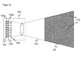
- FIG. 2 shows a schematic sectional view of the illumination unit 100 with a three-dimensional view of the projection plane of the resulting illumination pattern 20.
- the illumination unit 100 includes a light source 104, which is formed with a plurality of matrix-like arranged individual emitters 104a. For example, a two-dimensional VCSEL array is used for this purpose.
- a two-dimensional VCSEL array is used for this purpose.
- From the matrix arrangement of the individual emitter 104a only one line can be seen.
- the individual emitters 104a are regularly arranged in a conventional, commercially available VCSEL array.
- the resulting illumination pattern 20 should be irregular, stochastically distributed orsunä Siemens. Therefore, the light source 104 is preceded by a micro-optics array 106 having a plurality of micro-optics 106a.
- the micro-optics 106a are prisms shown purely schematically in this embodiment. An irregular arrangement of the micro-optics 106a results in different deflection directions for the respectively assigned individual emitters 104a. It is also conceivable to design the prisms alternatively or additionally with each other differently, so that they cause a different deflection even with the same relative position relative to the associated individual emitter 104a. Instead of prisms other non-imaging micro-optics can be used, for example by using a transmissive grating.
- the micro-optics array 106 formed as a prism field generates stochastically offset virtual dot images for each individual emitter 104a FIG. 2 are represented schematically by dot symbols 108.
- the dot symbols 108 therefore form an uneven line.
- the stochastic offset however, quite analogously also concerns the direction perpendicular to the paper plane.
- each pattern element 110 corresponds to a single emitter 104a whose transmission beam has been deflected by the non-imaging micro-optics array 106 from the originally regular arrangement. Therefore, the pattern elements 110 in their entirety form an irregular illumination pattern 20, which also imposes the structure required on a structureless scene and prevents the recognition of fake correspondences by a stereo algorithm. As an alternative to a stereo algorithm, the change in the expected structure of the illumination pattern 20 can be evaluated by objects in the scene.
- the individual emitters 104a can be operated with the same optical output power. Then, the individual pattern elements are equally bright among one another. In an advantageous development, however, this is purposefully deviated from, for example by the individual emitters 104a being driven with different currents. This can be achieved by the individual emitters 104a are individually controllable. Another possibility, in which worked with a uniform voltage and can be dispensed with an individual control, different designs of the individual emitter 104a, about different resistances in the leads by different line thicknesses or the like. This partial areas of the illumination pattern 20 are selectively lightened or darkened.
- the illumination pattern 20 can be changed in different variants of the 3D camera 10 by replacing the micro-optics array 106. Adaptability without conversion of the 3D camera 10 is possible by an advantageous development in which the individual emitters 104a are divided into two or even more groups. The groups can be controlled individually, so that their respective individual emitters 104a are selectively active or inactive, or have different brightness. In this way, different illumination patterns 20 can be generated with the same illumination unit 100 in order to adapt to applications, 3D cameras or sceneries. If a larger number of such groups is formed, the combinatorics of simultaneously active groups offers manifold possibilities of variation. In the limiting case, the individual emitters 104a are even individually controllable. It is then possible to choose the general packing density of the individual emitters 104a slightly higher than in embodiments without such groups, so that even if some groups are not active, the illumination pattern 20 still has the required degree of filling.
- the semiconductor array 104 it is conceivable to arrange the semiconductor array 104 so as to be displaceable relative to the imaging optics 108. By appropriate adjustment, a portion of the semiconductor array 104 is then selected, which is projected as illumination pattern 20. Also in this way an adjustment can be made.
Landscapes
- Engineering & Computer Science (AREA)
- Multimedia (AREA)
- Signal Processing (AREA)
- Physics & Mathematics (AREA)
- Electromagnetism (AREA)
- Length Measuring Devices By Optical Means (AREA)
- Testing, Inspecting, Measuring Of Stereoscopic Televisions And Televisions (AREA)
Applications Claiming Priority (1)
| Application Number | Priority Date | Filing Date | Title |
|---|---|---|---|
| DE102011052802.4A DE102011052802B4 (de) | 2011-08-18 | 2011-08-18 | 3D-Kamera und Verfahren zur Überwachung eines Raumbereichs |
Publications (3)
| Publication Number | Publication Date |
|---|---|
| EP2560366A2 true EP2560366A2 (fr) | 2013-02-20 |
| EP2560366A3 EP2560366A3 (fr) | 2013-03-06 |
| EP2560366B1 EP2560366B1 (fr) | 2013-09-18 |
Family
ID=46679098
Family Applications (1)
| Application Number | Title | Priority Date | Filing Date |
|---|---|---|---|
| EP12176554.9A Not-in-force EP2560366B1 (fr) | 2011-08-18 | 2012-07-16 | Caméra 3D et procédé de surveillance d'une pièce |
Country Status (3)
| Country | Link |
|---|---|
| US (1) | US20130044187A1 (fr) |
| EP (1) | EP2560366B1 (fr) |
| DE (1) | DE102011052802B4 (fr) |
Cited By (2)
| Publication number | Priority date | Publication date | Assignee | Title |
|---|---|---|---|---|
| EP2860714A1 (fr) * | 2013-10-09 | 2015-04-15 | Sick Ag | Dispositif optoélectronique et procédé de surveillance d'une zone de surveillance |
| EP3438691A1 (fr) * | 2017-08-04 | 2019-02-06 | Sick AG | Capteur optoelectronique et procédé de détection d'objets dans une zone de surveillance |
Families Citing this family (43)
| Publication number | Priority date | Publication date | Assignee | Title |
|---|---|---|---|---|
| CN104247178B (zh) * | 2012-03-01 | 2018-01-02 | Iee国际电子工程股份公司 | 空间编码结构化光生成器 |
| US20140307055A1 (en) * | 2013-04-15 | 2014-10-16 | Microsoft Corporation | Intensity-modulated light pattern for active stereo |
| US20150260830A1 (en) * | 2013-07-12 | 2015-09-17 | Princeton Optronics Inc. | 2-D Planar VCSEL Source for 3-D Imaging |
| US11019258B2 (en) | 2013-08-21 | 2021-05-25 | Verizon Patent And Licensing Inc. | Aggregating images and audio data to generate content |
| US9451162B2 (en) | 2013-08-21 | 2016-09-20 | Jaunt Inc. | Camera array including camera modules |
| US11265534B2 (en) * | 2014-02-08 | 2022-03-01 | Microsoft Technology Licensing, Llc | Environment-dependent active illumination for stereo matching |
| US9911454B2 (en) | 2014-05-29 | 2018-03-06 | Jaunt Inc. | Camera array including camera modules |
| US10368011B2 (en) | 2014-07-25 | 2019-07-30 | Jaunt Inc. | Camera array removing lens distortion |
| US11108971B2 (en) | 2014-07-25 | 2021-08-31 | Verzon Patent and Licensing Ine. | Camera array removing lens distortion |
| US9363569B1 (en) | 2014-07-28 | 2016-06-07 | Jaunt Inc. | Virtual reality system including social graph |
| US10186301B1 (en) | 2014-07-28 | 2019-01-22 | Jaunt Inc. | Camera array including camera modules |
| US10440398B2 (en) | 2014-07-28 | 2019-10-08 | Jaunt, Inc. | Probabilistic model to compress images for three-dimensional video |
| US10701426B1 (en) | 2014-07-28 | 2020-06-30 | Verizon Patent And Licensing Inc. | Virtual reality system including social graph |
| US9774887B1 (en) | 2016-09-19 | 2017-09-26 | Jaunt Inc. | Behavioral directional encoding of three-dimensional video |
| US20160072258A1 (en) * | 2014-09-10 | 2016-03-10 | Princeton Optronics Inc. | High Resolution Structured Light Source |
| US9854227B2 (en) | 2015-01-08 | 2017-12-26 | David G Grossman | Depth sensor |
| US9553423B2 (en) * | 2015-02-27 | 2017-01-24 | Princeton Optronics Inc. | Miniature structured light illuminator |
| US11149155B2 (en) | 2015-05-01 | 2021-10-19 | Sun Chemical Corporation | Electrically-insulating energy-curable inkjet fluids |
| KR102496374B1 (ko) * | 2015-07-29 | 2023-02-06 | 삼성전자주식회사 | 이미지 센서 |
| US11089286B2 (en) | 2015-07-29 | 2021-08-10 | Samsung Electronics Co., Ltd. | Image sensor |
| US10403668B2 (en) * | 2015-07-29 | 2019-09-03 | Samsung Electronics Co., Ltd. | Imaging apparatus and image sensor including the same |
| US10790325B2 (en) | 2015-07-29 | 2020-09-29 | Samsung Electronics Co., Ltd. | Imaging apparatus and image sensor including the same |
| US11469265B2 (en) | 2015-07-29 | 2022-10-11 | Samsung Electronics Co., Ltd. | Imaging apparatus and image sensor including the same |
| TWI708961B (zh) | 2015-08-13 | 2020-11-01 | 新加坡商海特根微光學公司 | 用於三維數據採集之照明組件 |
| WO2017039536A1 (fr) | 2015-08-28 | 2017-03-09 | Heptagon Micro Optics Pte. Ltd. | Modules d'éclairage pour la translation de lumière |
| US9992477B2 (en) | 2015-09-24 | 2018-06-05 | Ouster, Inc. | Optical system for collecting distance information within a field |
| KR102597579B1 (ko) | 2015-10-21 | 2023-11-01 | 프린스톤 옵트로닉스, 인크. | 코딩된 패턴 투영기 |
| US9989406B2 (en) * | 2016-01-29 | 2018-06-05 | Ouster, Inc. | Systems and methods for calibrating an optical distance sensor |
| DE102016109131B4 (de) * | 2016-05-18 | 2018-03-01 | Sick Ag | Verfahren zur dreidimensionalen Erfassung eines Objekts |
| US10241244B2 (en) | 2016-07-29 | 2019-03-26 | Lumentum Operations Llc | Thin film total internal reflection diffraction grating for single polarization or dual polarization |
| US10681341B2 (en) | 2016-09-19 | 2020-06-09 | Verizon Patent And Licensing Inc. | Using a sphere to reorient a location of a user in a three-dimensional virtual reality video |
| US11032535B2 (en) | 2016-09-19 | 2021-06-08 | Verizon Patent And Licensing Inc. | Generating a three-dimensional preview of a three-dimensional video |
| US11032536B2 (en) | 2016-09-19 | 2021-06-08 | Verizon Patent And Licensing Inc. | Generating a three-dimensional preview from a two-dimensional selectable icon of a three-dimensional reality video |
| DE102016118758B4 (de) * | 2016-10-04 | 2025-10-09 | Sick Ag | Optoelektronischer Sensor und Verfahren zur optischen Erfassung eines Überwachungsbereichs |
| CN107085343B (zh) * | 2017-03-10 | 2019-07-12 | 深圳奥比中光科技有限公司 | 结构光投影装置及深度相机 |
| US10928642B2 (en) | 2017-07-18 | 2021-02-23 | Ams Sensors Singapore Pte. Ltd. | Generating structured light |
| CN108319204A (zh) * | 2018-03-22 | 2018-07-24 | 京东方科技集团股份有限公司 | 智能控制方法及系统 |
| EP3572971B1 (fr) * | 2018-05-22 | 2021-02-24 | Sick Ag | Protection d'une zone de surveillance à au moins une machine |
| WO2020056722A1 (fr) * | 2018-09-21 | 2020-03-26 | 深圳阜时科技有限公司 | Structure de source de lumière, module de projection optique, dispositif de détection et appareil |
| US10694167B1 (en) | 2018-12-12 | 2020-06-23 | Verizon Patent And Licensing Inc. | Camera array including camera modules |
| JP7251240B2 (ja) * | 2019-03-20 | 2023-04-04 | 株式会社リコー | 光学装置、検出装置及び電子機器 |
| US12111147B2 (en) * | 2019-09-04 | 2024-10-08 | Ams Sensors Singapore Pte. Ltd. | Designing and constructing dot projectors for three-dimensional sensor modules |
| JP2022173763A (ja) * | 2021-05-10 | 2022-11-22 | セイコーエプソン株式会社 | 投写方法、及びプロジェクター |
Citations (6)
| Publication number | Priority date | Publication date | Assignee | Title |
|---|---|---|---|---|
| US20070263903A1 (en) | 2006-03-23 | 2007-11-15 | Tyzx, Inc. | Enhancing stereo depth measurements with projected texture |
| US20080240502A1 (en) | 2007-04-02 | 2008-10-02 | Barak Freedman | Depth mapping using projected patterns |
| WO2009093228A2 (fr) | 2008-01-21 | 2009-07-30 | Prime Sense Ltd. | Structures optiques pour réduction d'ordre zéro |
| EP2166304A1 (fr) | 2008-09-23 | 2010-03-24 | Sick Ag | Unité d'éclairage et procédé de production d'un modèle auto-dissemblable |
| US20100118123A1 (en) | 2007-04-02 | 2010-05-13 | Prime Sense Ltd | Depth mapping using projected patterns |
| DE102010017857A1 (de) | 2010-04-22 | 2011-10-27 | Sick Ag | 3D-Sicherheitsvorrichtung und Verfahren zur Absicherung und Bedienung mindestens einer Maschine |
Family Cites Families (17)
| Publication number | Priority date | Publication date | Assignee | Title |
|---|---|---|---|---|
| DE69636183T2 (de) * | 1995-03-31 | 2007-03-29 | Lintec Corp. | Vorrichtung zur Prüfung von Halbleitersubstraten |
| US5926601A (en) * | 1996-05-02 | 1999-07-20 | Briteview Technologies, Inc. | Stacked backlighting system using microprisms |
| DE69727125T2 (de) * | 1996-09-24 | 2004-11-11 | Seiko Epson Corp. | Projektionsanzeigevorrichtung mit einer lichtquelle |
| US6504649B1 (en) * | 2000-01-13 | 2003-01-07 | Kenneth J. Myers | Privacy screens and stereoscopic effects devices utilizing microprism sheets |
| US6556349B2 (en) * | 2000-12-27 | 2003-04-29 | Honeywell International Inc. | Variable focal length micro lens array field curvature corrector |
| DE20203462U1 (de) * | 2002-03-04 | 2003-07-10 | febit ag, 68167 Mannheim | Einrichtung zur Belichtung eines insbesondere optofluidischen Reaktionsträgers |
| US6951393B2 (en) * | 2002-07-31 | 2005-10-04 | Canon Kabushiki Kaisha | Projection type image display apparatus and image display system |
| JP4397394B2 (ja) * | 2003-01-24 | 2010-01-13 | ディジタル・オプティクス・インターナショナル・コーポレイション | 高密度照明システム |
| DE102004003013B3 (de) * | 2004-01-20 | 2005-06-02 | Fraunhofer-Gesellschaft zur Förderung der angewandten Forschung e.V. | Bilderfassungssystem und dessen Verwendung |
| US20070165243A1 (en) * | 2004-02-09 | 2007-07-19 | Cheol-Gwon Kang | Device for measuring 3d shape using irregular pattern and method for the same |
| DE112005003207B4 (de) * | 2004-12-22 | 2014-10-16 | Carl Zeiss Laser Optics Gmbh | Optisches Beleuchtungssystem zum Erzeugen eines Linienstrahls |
| JP4345811B2 (ja) * | 2006-12-27 | 2009-10-14 | セイコーエプソン株式会社 | 光学素子、転写型及び撮像装置 |
| US7871165B2 (en) * | 2007-11-30 | 2011-01-18 | Eastman Kodak Company | Stereo projection apparatus using polarized solid state light sources |
| DE112009001652T5 (de) * | 2008-07-08 | 2012-01-12 | Chiaro Technologies, Inc. | Mehrkanal-Erfassung |
| DE102009031732B3 (de) * | 2009-07-04 | 2010-11-25 | Sick Ag | Entfernungsmessender optoelektronischer Sensor |
| ATE514050T1 (de) * | 2009-07-27 | 2011-07-15 | Sick Ag | Beleuchtungsvorrichtung zur beleuchtung eines überwachungsbereichs |
| US8258722B2 (en) * | 2009-09-24 | 2012-09-04 | Cree, Inc. | Lighting device with defined spectral power distribution |
-
2011
- 2011-08-18 DE DE102011052802.4A patent/DE102011052802B4/de not_active Expired - Fee Related
-
2012
- 2012-07-16 EP EP12176554.9A patent/EP2560366B1/fr not_active Not-in-force
- 2012-08-17 US US13/588,651 patent/US20130044187A1/en not_active Abandoned
Patent Citations (6)
| Publication number | Priority date | Publication date | Assignee | Title |
|---|---|---|---|---|
| US20070263903A1 (en) | 2006-03-23 | 2007-11-15 | Tyzx, Inc. | Enhancing stereo depth measurements with projected texture |
| US20080240502A1 (en) | 2007-04-02 | 2008-10-02 | Barak Freedman | Depth mapping using projected patterns |
| US20100118123A1 (en) | 2007-04-02 | 2010-05-13 | Prime Sense Ltd | Depth mapping using projected patterns |
| WO2009093228A2 (fr) | 2008-01-21 | 2009-07-30 | Prime Sense Ltd. | Structures optiques pour réduction d'ordre zéro |
| EP2166304A1 (fr) | 2008-09-23 | 2010-03-24 | Sick Ag | Unité d'éclairage et procédé de production d'un modèle auto-dissemblable |
| DE102010017857A1 (de) | 2010-04-22 | 2011-10-27 | Sick Ag | 3D-Sicherheitsvorrichtung und Verfahren zur Absicherung und Bedienung mindestens einer Maschine |
Cited By (3)
| Publication number | Priority date | Publication date | Assignee | Title |
|---|---|---|---|---|
| EP2860714A1 (fr) * | 2013-10-09 | 2015-04-15 | Sick Ag | Dispositif optoélectronique et procédé de surveillance d'une zone de surveillance |
| EP3438691A1 (fr) * | 2017-08-04 | 2019-02-06 | Sick AG | Capteur optoelectronique et procédé de détection d'objets dans une zone de surveillance |
| US10436935B2 (en) | 2017-08-04 | 2019-10-08 | Sick Ag | Optoelectronic sensor and method of detecting objects in a monitored zone |
Also Published As
| Publication number | Publication date |
|---|---|
| EP2560366A3 (fr) | 2013-03-06 |
| EP2560366B1 (fr) | 2013-09-18 |
| US20130044187A1 (en) | 2013-02-21 |
| DE102011052802A1 (de) | 2013-02-21 |
| DE102011052802B4 (de) | 2014-03-13 |
Similar Documents
| Publication | Publication Date | Title |
|---|---|---|
| EP2560366B1 (fr) | Caméra 3D et procédé de surveillance d'une pièce | |
| EP2772676B1 (fr) | Caméra 3D et procédé de surveillance tridimensionnel d'un domaine de surveillance | |
| EP2469300B1 (fr) | Caméra 3D et procédé de surveillance tridimensionnel d'un domaine de surveillance | |
| DE202008017962U1 (de) | Beleuchtungseinheit zur Erzeugung eines selbstunähnlichen Musters | |
| AT514438B1 (de) | Fahrzeugscheinwerfer | |
| EP1933167B1 (fr) | Capteur optoélectronique et procédé correspondant de détection et de détermination de la distance d'un objet | |
| EP2166305B1 (fr) | Unité d'éclairage et procédé de projection d'un motif d'éclairage | |
| DE102010037744B3 (de) | Optoelektronischer Sensor | |
| EP2202994B1 (fr) | Caméra 3D pour la surveillance de pièces | |
| EP1939652B1 (fr) | Capteur de détermination d'objet | |
| DE202008013217U1 (de) | Beleuchtung zur Erzeugung eines Kontrastmusters | |
| EP2803906B1 (fr) | Appareil d'illumination et procédé pour produire un champ illuminé pour une caméra trois dimensionnelle | |
| EP3518000B1 (fr) | Capteur optoélectronique et procédé de détection d'objets | |
| EP3002548B1 (fr) | Dispositif d'éclairage et procédé destiné à la production d'une zone d'éclairage | |
| EP2083209A1 (fr) | Système de sécurité destiné à la mesure sans contact de voies et/ou de vitesses | |
| EP1884804A1 (fr) | Appareil de mesure de distance | |
| EP1947481A2 (fr) | Capteur optoélectronique et procédé de saisie d'objets dans une zone de surveillance | |
| DE202008017729U1 (de) | Dreidimensionale Überwachung und Absicherung eines Raumbereichs | |
| EP2280239B1 (fr) | Dispositif d'éclairage pour l'éclairage d'une zone de surveillance | |
| EP1065521A2 (fr) | Système de surveillance optoélectronique | |
| DE102016101884A1 (de) | Scheinwerfer | |
| DE102013007961A1 (de) | Optisches Messsystem für ein Fahrzeug | |
| DE202012104074U1 (de) | 3D-Kamera zur dreidimensionalen Überwachung eines Überwachungsbereichs | |
| DE102007048681B4 (de) | Linien-Beleuchtungsvorrichtung für einen Sensor | |
| EP2110699A2 (fr) | Dispositif et procédé destinés à l'éclairage d'une scène d'objet |
Legal Events
| Date | Code | Title | Description |
|---|---|---|---|
| PUAL | Search report despatched |
Free format text: ORIGINAL CODE: 0009013 |
|
| PUAI | Public reference made under article 153(3) epc to a published international application that has entered the european phase |
Free format text: ORIGINAL CODE: 0009012 |
|
| AK | Designated contracting states |
Kind code of ref document: A2 Designated state(s): AL AT BE BG CH CY CZ DE DK EE ES FI FR GB GR HR HU IE IS IT LI LT LU LV MC MK MT NL NO PL PT RO RS SE SI SK SM TR |
|
| AX | Request for extension of the european patent |
Extension state: BA ME |
|
| AK | Designated contracting states |
Kind code of ref document: A3 Designated state(s): AL AT BE BG CH CY CZ DE DK EE ES FI FR GB GR HR HU IE IS IT LI LT LU LV MC MK MT NL NO PL PT RO RS SE SI SK SM TR |
|
| AX | Request for extension of the european patent |
Extension state: BA ME |
|
| RIC1 | Information provided on ipc code assigned before grant |
Ipc: H04N 13/02 20060101ALI20130128BHEP Ipc: G01B 11/25 20060101ALI20130128BHEP Ipc: H04N 9/31 20060101ALI20130128BHEP Ipc: H04N 5/225 20060101AFI20130128BHEP |
|
| 17P | Request for examination filed |
Effective date: 20130426 |
|
| GRAP | Despatch of communication of intention to grant a patent |
Free format text: ORIGINAL CODE: EPIDOSNIGR1 |
|
| RIC1 | Information provided on ipc code assigned before grant |
Ipc: H04N 5/225 20060101AFI20130514BHEP Ipc: G01B 11/25 20060101ALI20130514BHEP Ipc: H04N 13/02 20060101ALI20130514BHEP Ipc: H04N 9/31 20060101ALI20130514BHEP |
|
| INTG | Intention to grant announced |
Effective date: 20130620 |
|
| GRAS | Grant fee paid |
Free format text: ORIGINAL CODE: EPIDOSNIGR3 |
|
| GRAA | (expected) grant |
Free format text: ORIGINAL CODE: 0009210 |
|
| RBV | Designated contracting states (corrected) |
Designated state(s): AL AT BE BG CH CY CZ DE DK EE ES FI FR GB GR HR HU IE IS IT LI LT LU LV MC MK MT NL NO PL PT RO RS SE SI SK SM TR |
|
| AK | Designated contracting states |
Kind code of ref document: B1 Designated state(s): AL AT BE BG CH CY CZ DE DK EE ES FI FR GB GR HR HU IE IS IT LI LT LU LV MC MK MT NL NO PL PT RO RS SE SI SK SM TR |
|
| REG | Reference to a national code |
Ref country code: GB Ref legal event code: FG4D Free format text: NOT ENGLISH |
|
| REG | Reference to a national code |
Ref country code: CH Ref legal event code: EP |
|
| REG | Reference to a national code |
Ref country code: IE Ref legal event code: FG4D Free format text: LANGUAGE OF EP DOCUMENT: GERMAN |
|
| REG | Reference to a national code |
Ref country code: AT Ref legal event code: REF Ref document number: 633306 Country of ref document: AT Kind code of ref document: T Effective date: 20131015 |
|
| REG | Reference to a national code |
Ref country code: DE Ref legal event code: R096 Ref document number: 502012000131 Country of ref document: DE Effective date: 20131114 |
|
| PG25 | Lapsed in a contracting state [announced via postgrant information from national office to epo] |
Ref country code: SE Free format text: LAPSE BECAUSE OF FAILURE TO SUBMIT A TRANSLATION OF THE DESCRIPTION OR TO PAY THE FEE WITHIN THE PRESCRIBED TIME-LIMIT Effective date: 20130918 Ref country code: NO Free format text: LAPSE BECAUSE OF FAILURE TO SUBMIT A TRANSLATION OF THE DESCRIPTION OR TO PAY THE FEE WITHIN THE PRESCRIBED TIME-LIMIT Effective date: 20131218 Ref country code: CY Free format text: LAPSE BECAUSE OF FAILURE TO SUBMIT A TRANSLATION OF THE DESCRIPTION OR TO PAY THE FEE WITHIN THE PRESCRIBED TIME-LIMIT Effective date: 20130918 Ref country code: LT Free format text: LAPSE BECAUSE OF FAILURE TO SUBMIT A TRANSLATION OF THE DESCRIPTION OR TO PAY THE FEE WITHIN THE PRESCRIBED TIME-LIMIT Effective date: 20130918 Ref country code: HR Free format text: LAPSE BECAUSE OF FAILURE TO SUBMIT A TRANSLATION OF THE DESCRIPTION OR TO PAY THE FEE WITHIN THE PRESCRIBED TIME-LIMIT Effective date: 20130918 |
|
| REG | Reference to a national code |
Ref country code: NL Ref legal event code: VDEP Effective date: 20130918 |
|
| REG | Reference to a national code |
Ref country code: LT Ref legal event code: MG4D |
|
| PG25 | Lapsed in a contracting state [announced via postgrant information from national office to epo] |
Ref country code: RS Free format text: LAPSE BECAUSE OF FAILURE TO SUBMIT A TRANSLATION OF THE DESCRIPTION OR TO PAY THE FEE WITHIN THE PRESCRIBED TIME-LIMIT Effective date: 20130918 Ref country code: LV Free format text: LAPSE BECAUSE OF FAILURE TO SUBMIT A TRANSLATION OF THE DESCRIPTION OR TO PAY THE FEE WITHIN THE PRESCRIBED TIME-LIMIT Effective date: 20130918 Ref country code: FI Free format text: LAPSE BECAUSE OF FAILURE TO SUBMIT A TRANSLATION OF THE DESCRIPTION OR TO PAY THE FEE WITHIN THE PRESCRIBED TIME-LIMIT Effective date: 20130918 Ref country code: GR Free format text: LAPSE BECAUSE OF FAILURE TO SUBMIT A TRANSLATION OF THE DESCRIPTION OR TO PAY THE FEE WITHIN THE PRESCRIBED TIME-LIMIT Effective date: 20131219 |
|
| PG25 | Lapsed in a contracting state [announced via postgrant information from national office to epo] |
Ref country code: CZ Free format text: LAPSE BECAUSE OF FAILURE TO SUBMIT A TRANSLATION OF THE DESCRIPTION OR TO PAY THE FEE WITHIN THE PRESCRIBED TIME-LIMIT Effective date: 20130918 Ref country code: NL Free format text: LAPSE BECAUSE OF FAILURE TO SUBMIT A TRANSLATION OF THE DESCRIPTION OR TO PAY THE FEE WITHIN THE PRESCRIBED TIME-LIMIT Effective date: 20130918 Ref country code: EE Free format text: LAPSE BECAUSE OF FAILURE TO SUBMIT A TRANSLATION OF THE DESCRIPTION OR TO PAY THE FEE WITHIN THE PRESCRIBED TIME-LIMIT Effective date: 20130918 Ref country code: SK Free format text: LAPSE BECAUSE OF FAILURE TO SUBMIT A TRANSLATION OF THE DESCRIPTION OR TO PAY THE FEE WITHIN THE PRESCRIBED TIME-LIMIT Effective date: 20130918 Ref country code: IS Free format text: LAPSE BECAUSE OF FAILURE TO SUBMIT A TRANSLATION OF THE DESCRIPTION OR TO PAY THE FEE WITHIN THE PRESCRIBED TIME-LIMIT Effective date: 20140118 |
|
| PG25 | Lapsed in a contracting state [announced via postgrant information from national office to epo] |
Ref country code: PL Free format text: LAPSE BECAUSE OF FAILURE TO SUBMIT A TRANSLATION OF THE DESCRIPTION OR TO PAY THE FEE WITHIN THE PRESCRIBED TIME-LIMIT Effective date: 20130918 Ref country code: ES Free format text: LAPSE BECAUSE OF FAILURE TO SUBMIT A TRANSLATION OF THE DESCRIPTION OR TO PAY THE FEE WITHIN THE PRESCRIBED TIME-LIMIT Effective date: 20130918 |
|
| REG | Reference to a national code |
Ref country code: DE Ref legal event code: R097 Ref document number: 502012000131 Country of ref document: DE |
|
| PG25 | Lapsed in a contracting state [announced via postgrant information from national office to epo] |
Ref country code: PT Free format text: LAPSE BECAUSE OF FAILURE TO SUBMIT A TRANSLATION OF THE DESCRIPTION OR TO PAY THE FEE WITHIN THE PRESCRIBED TIME-LIMIT Effective date: 20140120 |
|
| PLBE | No opposition filed within time limit |
Free format text: ORIGINAL CODE: 0009261 |
|
| STAA | Information on the status of an ep patent application or granted ep patent |
Free format text: STATUS: NO OPPOSITION FILED WITHIN TIME LIMIT |
|
| 26N | No opposition filed |
Effective date: 20140619 |
|
| PG25 | Lapsed in a contracting state [announced via postgrant information from national office to epo] |
Ref country code: IT Free format text: LAPSE BECAUSE OF FAILURE TO SUBMIT A TRANSLATION OF THE DESCRIPTION OR TO PAY THE FEE WITHIN THE PRESCRIBED TIME-LIMIT Effective date: 20130918 |
|
| PG25 | Lapsed in a contracting state [announced via postgrant information from national office to epo] |
Ref country code: DK Free format text: LAPSE BECAUSE OF FAILURE TO SUBMIT A TRANSLATION OF THE DESCRIPTION OR TO PAY THE FEE WITHIN THE PRESCRIBED TIME-LIMIT Effective date: 20130918 |
|
| REG | Reference to a national code |
Ref country code: DE Ref legal event code: R097 Ref document number: 502012000131 Country of ref document: DE Effective date: 20140619 |
|
| PG25 | Lapsed in a contracting state [announced via postgrant information from national office to epo] |
Ref country code: LU Free format text: LAPSE BECAUSE OF FAILURE TO SUBMIT A TRANSLATION OF THE DESCRIPTION OR TO PAY THE FEE WITHIN THE PRESCRIBED TIME-LIMIT Effective date: 20140716 |
|
| PG25 | Lapsed in a contracting state [announced via postgrant information from national office to epo] |
Ref country code: IE Free format text: LAPSE BECAUSE OF NON-PAYMENT OF DUE FEES Effective date: 20140716 |
|
| PG25 | Lapsed in a contracting state [announced via postgrant information from national office to epo] |
Ref country code: SM Free format text: LAPSE BECAUSE OF FAILURE TO SUBMIT A TRANSLATION OF THE DESCRIPTION OR TO PAY THE FEE WITHIN THE PRESCRIBED TIME-LIMIT Effective date: 20130918 Ref country code: MC Free format text: LAPSE BECAUSE OF FAILURE TO SUBMIT A TRANSLATION OF THE DESCRIPTION OR TO PAY THE FEE WITHIN THE PRESCRIBED TIME-LIMIT Effective date: 20130918 |
|
| PG25 | Lapsed in a contracting state [announced via postgrant information from national office to epo] |
Ref country code: RO Free format text: LAPSE BECAUSE OF FAILURE TO SUBMIT A TRANSLATION OF THE DESCRIPTION OR TO PAY THE FEE WITHIN THE PRESCRIBED TIME-LIMIT Effective date: 20130918 |
|
| PG25 | Lapsed in a contracting state [announced via postgrant information from national office to epo] |
Ref country code: MT Free format text: LAPSE BECAUSE OF FAILURE TO SUBMIT A TRANSLATION OF THE DESCRIPTION OR TO PAY THE FEE WITHIN THE PRESCRIBED TIME-LIMIT Effective date: 20130918 Ref country code: BG Free format text: LAPSE BECAUSE OF FAILURE TO SUBMIT A TRANSLATION OF THE DESCRIPTION OR TO PAY THE FEE WITHIN THE PRESCRIBED TIME-LIMIT Effective date: 20130918 |
|
| REG | Reference to a national code |
Ref country code: FR Ref legal event code: PLFP Year of fee payment: 5 |
|
| PG25 | Lapsed in a contracting state [announced via postgrant information from national office to epo] |
Ref country code: BE Free format text: LAPSE BECAUSE OF FAILURE TO SUBMIT A TRANSLATION OF THE DESCRIPTION OR TO PAY THE FEE WITHIN THE PRESCRIBED TIME-LIMIT Effective date: 20140731 Ref country code: HU Free format text: LAPSE BECAUSE OF FAILURE TO SUBMIT A TRANSLATION OF THE DESCRIPTION OR TO PAY THE FEE WITHIN THE PRESCRIBED TIME-LIMIT; INVALID AB INITIO Effective date: 20120716 Ref country code: TR Free format text: LAPSE BECAUSE OF FAILURE TO SUBMIT A TRANSLATION OF THE DESCRIPTION OR TO PAY THE FEE WITHIN THE PRESCRIBED TIME-LIMIT Effective date: 20130918 Ref country code: SI Free format text: LAPSE BECAUSE OF FAILURE TO SUBMIT A TRANSLATION OF THE DESCRIPTION OR TO PAY THE FEE WITHIN THE PRESCRIBED TIME-LIMIT Effective date: 20130918 |
|
| REG | Reference to a national code |
Ref country code: FR Ref legal event code: PLFP Year of fee payment: 6 |
|
| PG25 | Lapsed in a contracting state [announced via postgrant information from national office to epo] |
Ref country code: MK Free format text: LAPSE BECAUSE OF FAILURE TO SUBMIT A TRANSLATION OF THE DESCRIPTION OR TO PAY THE FEE WITHIN THE PRESCRIBED TIME-LIMIT Effective date: 20130918 |
|
| REG | Reference to a national code |
Ref country code: FR Ref legal event code: PLFP Year of fee payment: 7 |
|
| REG | Reference to a national code |
Ref country code: AT Ref legal event code: MM01 Ref document number: 633306 Country of ref document: AT Kind code of ref document: T Effective date: 20170716 |
|
| PG25 | Lapsed in a contracting state [announced via postgrant information from national office to epo] |
Ref country code: AL Free format text: LAPSE BECAUSE OF FAILURE TO SUBMIT A TRANSLATION OF THE DESCRIPTION OR TO PAY THE FEE WITHIN THE PRESCRIBED TIME-LIMIT Effective date: 20130918 |
|
| PG25 | Lapsed in a contracting state [announced via postgrant information from national office to epo] |
Ref country code: AT Free format text: LAPSE BECAUSE OF NON-PAYMENT OF DUE FEES Effective date: 20170716 |
|
| PGFP | Annual fee paid to national office [announced via postgrant information from national office to epo] |
Ref country code: FR Payment date: 20190724 Year of fee payment: 8 Ref country code: DE Payment date: 20190723 Year of fee payment: 8 |
|
| PGFP | Annual fee paid to national office [announced via postgrant information from national office to epo] |
Ref country code: GB Payment date: 20190725 Year of fee payment: 8 |
|
| PGFP | Annual fee paid to national office [announced via postgrant information from national office to epo] |
Ref country code: CH Payment date: 20190725 Year of fee payment: 8 |
|
| REG | Reference to a national code |
Ref country code: DE Ref legal event code: R119 Ref document number: 502012000131 Country of ref document: DE |
|
| REG | Reference to a national code |
Ref country code: CH Ref legal event code: PL |
|
| GBPC | Gb: european patent ceased through non-payment of renewal fee |
Effective date: 20200716 |
|
| PG25 | Lapsed in a contracting state [announced via postgrant information from national office to epo] |
Ref country code: CH Free format text: LAPSE BECAUSE OF NON-PAYMENT OF DUE FEES Effective date: 20200731 Ref country code: LI Free format text: LAPSE BECAUSE OF NON-PAYMENT OF DUE FEES Effective date: 20200731 Ref country code: FR Free format text: LAPSE BECAUSE OF NON-PAYMENT OF DUE FEES Effective date: 20200731 Ref country code: GB Free format text: LAPSE BECAUSE OF NON-PAYMENT OF DUE FEES Effective date: 20200716 |
|
| PG25 | Lapsed in a contracting state [announced via postgrant information from national office to epo] |
Ref country code: DE Free format text: LAPSE BECAUSE OF NON-PAYMENT OF DUE FEES Effective date: 20210202 |