EP2560437B1 - Prozessverfahren, vorrichtung und system für umgekehrte einzelfunk-sprachanrufkontinuität - Google Patents
Prozessverfahren, vorrichtung und system für umgekehrte einzelfunk-sprachanrufkontinuität Download PDFInfo
- Publication number
- EP2560437B1 EP2560437B1 EP11777270.7A EP11777270A EP2560437B1 EP 2560437 B1 EP2560437 B1 EP 2560437B1 EP 11777270 A EP11777270 A EP 11777270A EP 2560437 B1 EP2560437 B1 EP 2560437B1
- Authority
- EP
- European Patent Office
- Prior art keywords
- domain network
- information
- network
- user equipment
- switched domain
- Prior art date
- Legal status (The legal status is an assumption and is not a legal conclusion. Google has not performed a legal analysis and makes no representation as to the accuracy of the status listed.)
- Active
Links
Images



Classifications
-
- H—ELECTRICITY
- H04—ELECTRIC COMMUNICATION TECHNIQUE
- H04W—WIRELESS COMMUNICATION NETWORKS
- H04W36/00—Hand-off or reselection arrangements
- H04W36/0005—Control or signalling for completing the hand-off
- H04W36/0011—Control or signalling for completing the hand-off for data sessions of end-to-end connection
- H04W36/0022—Control or signalling for completing the hand-off for data sessions of end-to-end connection for transferring data sessions between adjacent core network technologies
- H04W36/00224—Control or signalling for completing the hand-off for data sessions of end-to-end connection for transferring data sessions between adjacent core network technologies between packet switched [PS] and circuit switched [CS] network technologies, e.g. circuit switched fallback [CSFB]
- H04W36/00226—Control or signalling for completing the hand-off for data sessions of end-to-end connection for transferring data sessions between adjacent core network technologies between packet switched [PS] and circuit switched [CS] network technologies, e.g. circuit switched fallback [CSFB] wherein the core network technologies comprise IP multimedia system [IMS], e.g. single radio voice call continuity [SRVCC]
Definitions
- Embodiments of the present invention relate to the field of communications technologies, and in particular to a method, device and system for processing reverse single radio voice call continuity.
- a network of the 2nd generation mobile communications technology (2nd Generation, 2G) or 3rd generation mobile communications technology (3rd Generation, 3G for short) achieves comprehensive coverage after being deployed for many years.
- some PS domain - only networks that only provide packet switches (Packet Switch, PS for short) for example, a Long Term Evolution (Long Term Evolution, LTE for short) network, gradually cover some urban areas and areas with high traffic in the initial stage of network construction. Therefore, these PS domain - only networks and the 2G/3G network coexist in a current communications network.
- a voice service has different bearing mechanisms. Specifically, in the 2G/3G network, a voice call supports a conversational-class service borne by a circuit switched (Circuit Switched, CS for short) domain; whereas in a PS domain network, a voice call supports a conversational-class service borne by a packet switched (Packet Switched, PS for short) domain, which is also referred to as a voice over Internet Protocol (Voice over Internet Protocol, VOIP for short) service, where quality of service is ensured by an IP multimedia subsystem (IP Multimedia Subsystem, IMS for short).
- IP Multimedia Subsystem IP Multimedia Subsystem
- the PS domain network is capable of providing a voice service with a higher rate and higher quality for a user and satisfying more data service requirements of the user. Therefore, to develop more voice users of the PS domain network, an operator usually sets a priority of the PS domain higher than that of the CS domain to enable a voice user to preferably camp on the PS domain network.
- a user equipment User Equipment, UE for short
- UE User Equipment
- the UE needs to hand over the voice call from the CS domain to the PS domain of the LTE/HSPA network, that is, performing a procedure for processing reverse single radio voice call continuity (Single Radio Voice Call Continuity, SRVCC for short).
- SRVCC Single Radio Voice Call Continuity
- the existing reverse SRVCC processing is generally implemented by using the following two solutions.
- the first solution is that when performing the reverse SRVCC processing, the UE enables the voice service to exit from the 2G/3G CS domain network first and then access the LTE network, and initiates an access transfer processing procedure.
- the UE for a network access procedure, the UE enables the voice service to access the LTE network quickly, which avoids large voice interruption delay and does not affect user experience of voice continuity.
- duration varies according to different application scenarios and the shortest needed duration is highly greater than the needed minimum value 300 ms of interruption delay during the voice handover, which severely affects voice continuity during the reverse SRVCC handover and causes poor quality of service.
- the second reverse SRVCC processing solution is that when performing the reverse SRVCC processing, the UE hands over, in the 2G/3G network, a bearer of the voice service from the CS domain to the PS domain first, that is, performing an access transfer in the 2G/3G network first, and then performs access to the LTE network to completely hand over the voice service to the PS domain of the LTE network.
- the PS domain voice service supported by a 2G/3G PS domain network is only capable of providing services of low quality for the UE, and therefore the user cannot enjoy a voice service with good quality for a long period of time.
- US 2010/054207 A1 discloses a method of single radio handover between WiMAX and 2G/3G/4G, where a bearer path is set up between the WiMAX ASN and the Serving Gateway to use for data packet forwarding between the 3GPP and WiMAX networks.
- WO 2010/052343 A2 discloses a mobility management node allowing for a session transfer of a call involving a UE of a handover party from a CS access towards a target PS access.
- Document 3GPP TR 23.885 V0.3.0 discloses a scenario of CS to PS access transfer.
- Embodiments of the present invention provide a method, device and system for processing reverse single radio voice call continuity to resolve the defect of a failure in ensuring good voice continuity or of low quality of service in a voice handover procedure, which is caused by high interruption delay during the voice handover in the existing reverse SRVCC technology.
- an embodiment of the present invention provides a method for processing reverse single radio voice call continuity, including:
- an embodiment of the present invention further provides a mobility management entity, including:
- an embodiment of the present invention provides a system for processing reverse single radio voice call continuity, including a user equipment, a first network element, a second network element, and a mobility management entity, where:
- the UE before a UE hands over a voice service from a CS domain network to a PS domain network, the UE preconfigures, in the PS domain network, information about bearer resources needed for the voice handover.
- a forwarding channel of voice data is established between the CS domain network and the PS domain network by using information about a reserved bearer, in which the information is preallocated by the PS domain network for the UE.
- the UE is capable of quickly transmitting voice data with a peer user equipment through the established forwarding channel without the need of waiting a long time before an access transfer procedure is completed. This ensures good performance of voice service continuity in the reverse SRVCC handover procedure.
- the forwarding channel is established on the basis that the UE completes the access to the PS domain network. Therefore, the voice service performed based on the forwarding channel is further capable of achieving good quality of the voice service.
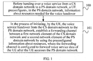
- FIG. 1 is a flow chart of a method for processing reverse single radio voice call continuity according to Embodiment 1 of the present invention. As shown in FIG. 1 , the method includes the following steps:
- the UE before the UE initiates the voice service handover from the CS domain network to the PS domain network, in order to preconfigure, in the PS domain network, information about resources for handing over a bearer of the voice service to the PS domain network so that after a reverse SRVCC handover process is actually initiated, a core network element in the PS domain network is capable of quickly establishing a new voice bearer channel between the UE and a peer user equipment by using preallocated bearer resources, the UE completes in advance, in the PS domain network, its configuration on the user media layer in the core network element of the PS domain network before initiating the voice service handover. In this manner, information about certain resources for transmitting voice data packets is preconfigured in the PS domain network.
- the preparation process occurs before the UE initiates the reverse SRVCC handover of the voice service.
- the UE completes in advance, in the PS domain network, for example, an LTE network, the configuration on the user media layer so that the core network element of the PS domain network is capable of preallocating, for the UE, information about resources needed for bearing a VOIP voice service in the PS domain network, for example, an IP address, a number, and a codec that are needed by the UE to bear the voice service in the PS domain network.
- the PS domain network for example, an LTE network
- the configuration on the user media layer so that the core network element of the PS domain network is capable of preallocating, for the UE, information about resources needed for bearing a VOIP voice service in the PS domain network, for example, an IP address, a number, and a codec that are needed by the UE to bear the voice service in the PS domain network.
- a control network element is capable of quickly establishing a new voice bearer channel between the UE and the peer user equipment by using the preallocated information about resources to ensure continuity of the voice service of the UE in a handover process.
- Step 101 In the process of initiating, by the UE, the voice service handover from the CS domain network to the PS domain network, establish a forwarding channel between a first network element of the PS domain network and a second network element of the CS domain network by using the preconfigured information about resources, where the forwarding channel is configured to forward voice service data of the UE after the UE accesses the PS domain network.
- the PS domain network In the process of actually initiating, by the UE, the voice service handover from the CS domain to the PS domain, before the UE performs the reverse SRVCC handover, the PS domain network has preallocated, for the UE, information about resources for bearing a related service of the UE in the PS domain network, and therefore in the handover process, the PS domain network may quickly establish, by using the preconfigured information about resources, a new data forwarding channel between the UE and the peer user equipment for exchanging voice data.
- a forwarding channel is established between the first network element in the PS domain network and the second network element in the CS domain network by using information about reserved resources preallocated by the PS domain network for the UE in the pre-registration process performed by the UE.
- the forwarding channel is configured to forward voice data exchanged between the UE and a peer UE after the UE accesses the PS domain network, specifically, accesses an evolved NodeB (Evolved Node B, ENB for short) of the PS domain network and before the UE performs an access transfer procedure, which is equal to providing a new path for the UE and the peer UE to perform a voice session.
- Evolved Node B evolved Node B
- the PS domain network has preallocated, for the UE, the information about resources for bearing a service of the UE in the PS domain. Based on the preconfigured information about resources, the forwarding channel between the first network element and the second network element can be quickly established without depending on completion of the access transfer process in the reverse SRVCC handover procedure performed by the UE. At the same time, in regard to the UE, in the reverse SRVCC handover procedure, the UE is further capable of quickly completing an access operation in the PS domain network to access the ENB of the PS domain network.
- the UE may immediately perform voice data exchange with the peer UE through the forwarding channel without the need of waiting a long time for the completion of the access transfer procedure.
- an MME may quickly hand over, in the PS domain network environment, the voice service of the UE to a VOIP bearer of the PS domain network in a short period of time so that the UE quickly establishes voice communication with the peer user equipment.
- the interruption delay during the reverse SRVCC voice handover in this embodiment is not affected even when the completion of the access transfer needs a long duration, thereby ensuring good voice continuity of the voice service in the handover process.
- a new forwarding channel is established on the basis that the UE completes the access to the PS domain network. Therefore, the voice service of the UE based on the forwarding channel belongs to the VOIP voice service class of the PS domain network. In this case, compared with the transition solution of the PS domain voice service of the 2G/3G network in the prior art, the forwarding channel is also capable of ensuring that the voice service of the UE achieves good quality of service in the handover process.
- the UE preconfigures, in the PS domain network, information about bearer resources needed for completing the voice service handover.
- a forwarding channel of voice data is established between the CS domain network and the PS domain network by using information about a reserved bearer, in which the information is preallocated by the PS domain network for the UE.
- the UE is capable of quickly transmitting voice data with a peer user equipment through the established forwarding channel without the need of waiting a long time for the completion of an access transfer procedure. This ensures good performance of voice service continuity in the reverse SRVCC handover process.
- the forwarding channel is established on the basis that the UE completes the access to the PS domain network. Therefore, the voice service performed based on the forwarding channel is further capable of achieving good quality of the voice service.
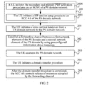
- FIG. 2 is a flow chart of a method for processing reverse single radio voice call continuity according to a second embodiment of the present invention. As shown in FIG. 2 , the method includes the following steps:
- the preconfiguring, by the UE, the information about resources in the PS domain network before handing over the voice service from the CS domain network to the PS domain network may specifically be implemented by using the procedure in which the UE performs IMS registration and sets up a SIP session in the PS domain network.
- the process of preconfiguring the information about resources may include the following substeps:
- the UE Before handing over the voice service from the CS domain network to the PS domain network, the UE may complete registration in the PS domain network in advance according to a registration procedure stipulated in the protocol. Specifically, the UE may sequentially initiates and completes the attach (Attach) procedure and the primary PDP activation procedure on an SGSN device of the PS domain network according to procedures stipulated in the protocol.
- the UE may negotiate, with the SGSN, information needed by the UE to initiate a voice call in the PS domain network, for example, voice codec (CodeC) information of the UE in the PS domain network and information about a session transfer number for SRVCC (Session Transfer Number for Single Radio Voice Call Continuity, STN-SR for short), and enable the PS domain network to allocate needed resources for the UE.
- codeC voice codec
- the UE may carry, in an attach request sent to the SGSN, CodeC information that is supported by default in the PS domain network.
- the SGSN may learn the corresponding codec type of the UE in the PS domain.
- the UE may further initiates a secondary PDP activation procedure to the SGSN, where the secondary PDP activation procedure assists the primary PDP activation procedure.
- the UE may specify, to the SGSN, the class of service of the UE in the current PS domain network registration, for example, specifying that the current registration procedure is specifically used for the voice service.
- Step 2001 The UE initiates a SIP session setup process to a service centralization and continuity application server (Service Centralization and Continuity Application Server, SCC AS for short) of the PS domain network.
- a service centralization and continuity application server Service Centralization and Continuity Application Server, SCC AS for short
- the UE may further initiate a SIP session setup request to the SCC AS and pre-establish a reserved SIP session connection in the PS domain network by initiating the process of setting up a SIP session with the SCC AS.
- the initiating, by the UE, the SIP session setup request does not aim to actually set up a SIP session with a peer UE.
- the pre-established SIP session connection may not actually function before the UE initiates a voice service handover from the CS domain network to the PS domain network, and may be used only for allocating corresponding resources for the UE in a core network of the PS domain network and does not transmit any data.
- the SCC AS does not need to initiate an actual call to the peer UE.
- the UE may quickly hand over the voice service to VOIP voice of the PS domain based on the preallocated resources and perform a subsequent access transfer procedure for the voice service. In this manner, a SIP session does not need to be initiated temporarily in the subsequent access transfer procedure, which is equal to accelerating the subsequent access transfer procedure.
- the UE may carry special reverse SRVCC indication information in the SIP session setup request sent to the SCC AS, where the reverse SRVCC indication information is used to indicate to the SCC AS that the SIP session set up currently is used in a subsequent reverse SRVCC handover procedure, thereby indicating that the SCC AS does not need to initiate an actual call to the peer UE when setting up the SIP session for the UE according to the SIP session setup request.
- the UE before the UE performs the reverse SRVCC handover, both the SIP session set up in advance for the UE in the PS domain network and the information about resources preconfigured by the UE are not used to actually transmit voice data.
- the reverse SRVCC indication information which is carried by the UE in the SIP session setup request sent to the SCC AS, may further be used to indicate that the SCC AS does not need to proactively trigger the process of releasing the information about resources of the UE even when no data is transmitted on the reserved SIP session connection for a long period of time.
- the carrying, by the UE, the reverse SRVCC indication information in the SIP session setup request sent to the SCC AS may specifically be implemented in the following two manners: the UE may separately carry a piece of indication information in the SIP session setup request, for example, rSRVCC indicator information, where the rSRVCC indicator information indicates to the SCC AS that the established SIP session is actually used in a subsequent reverse SRVCC handover; or the UE may also carry a special called number in the SIP session setup request sent to the SCC AS, where the special called number may be a particular number for the reverse SRVCC handover.
- the special called number may be a particular number for the reverse SRVCC handover.
- the SCC AS may also learn that the SIP session is used in the reverse SRVCC handover, and therefore may only negotiate, in the SIP session setup process, allocation of information about needed bearer resources with the UE rather than actually initiate a voice call to the peer UE.
- the UE may further send another piece of indication information to the SGSN besides sending the reverse SRVCC indication information to the SCC AS.
- the indication information is used to indicate that the SGSN does not need to initiate a radio access bearer (Radio Access Bearer, RAB for short) establishment process after the SIP session is set up in the PS domain network for the UE.
- RAB Radio Access Bearer
- the UE sends the indication information to indicate that the SGSN does not need to initiate the RAB establishment process because before the reverse SRVCC handover, the actual function of establishing the SIP session connection for the UE is preparing for the subsequent reverse SRVCC handover process.
- the SIP session connection does not transmit any voice data of the UE. Therefore, accordingly, the SGSN does not need to initiate an actual RAB establishment process, thereby avoiding a waste of resources.
- the UE may send the indication information to the SGSN according to the following methods. If the SGSN supports Gn/Gp mode, the UE may set a corresponding identifier bit, for example, setting a field of the maximum bite rate (Maximum Bit Rate, MBR for short) to 0, when sending a primary PDP activation request to the SGSN in the primary PDP activation process in step 2000, so as to notify the SGSN that the RAB establishment process does not need to be initiated.
- MBR Maximum Bit Rate
- the UE may also carry the indication information in the primary PDP activation request sent to the SGSN, so as to indicate to the SGSN that the VOIP voice bearer is reserved for the reverse SRVCC handover, thereby indicating that the SGSN does not need to initiate the RAB establishment process.
- the UE may also not add any special indication. After the SGSN receives the primary PDP activation request sent by the UE, if the network does not support the capability of establishing a PS domain voice service, the SGSN also does not trigger the RAB establishment process.
- the UE may set the Traffic Class parameter to a conversational class among parameters of quality of service (Quality of Service, QoS for short) that are carried in the request, so as to notify the SGSN that the RAB establishment process does not need to be triggered.
- Quality of Service Quality of Service
- the UE may further negotiate, with the SCC. AS, the CodeC information of the UE in the PS domain network. After negotiation is successful, the SCC AS carries negotiated CodeC information in a SIP response message and returns the SIP response message to the UE.
- information identifying, for example, a destination IP address of service sending of the UE in the PS domain network may also be negotiated by the UE and the SCC AS in the signaling interaction process, and negotiated IP address information is carried by the SCC AS in the SIP response message and returned to the UE together with the CodeC information.
- the PS domain network preallocates, for the UE, information about reserved resources for the UE to transmit voice data in the PS domain network.
- the information about reserved resources includes information such as an STN-SR number, an IP address, or CodeC information of the UE in the PS domain network.
- the information about reserved resources should also include at least first information that is allocated by a first network element of the PS domain network, for example, an access transfer gateway (Access Transfer Gateway, ATGW for short) or a packet data network gateway (Packet Data Network Gateway, PGW for short), to the UE for the reverse SRVCC handover.
- a first network element of the PS domain network for example, an access transfer gateway (Access Transfer Gateway, ATGW for short) or a packet data network gateway (Packet Data Network Gateway, PGW for short), to the UE for the reverse SRVCC handover.
- ATGW Access Transfer Gateway
- PGW Packet Data Network Gateway
- the first information may specifically include information such as an IP address and/or a port allocated by the first network element for the UE.
- Other network elements in the network are capable of identifying the first network element based on the first information, thereby establishing a data forwarding channel with the first network element.
- the information about the port preallocated by the first network element may specifically be: in the first network element, the information about a port reserved in advance for the reverse SRVCC handover, that is, the first network element may specify in advance a particular port for the reverse SRVCC handover process.
- the first network element when the first network element allocates the first information for the UE, the first network element does not need to allocate a port for the UE temporarily, and instead may allocate, to the UE, the information about the port specified in advance.
- the ATGW is generally deployed together with an access transfer control functionality (Access Transfer Control Functionality, ATCF for short). Therefore, in this embodiment, when the first network element is subsequently referred to as the ATGW, the first network element is referred to as the ATCF/ATGW instead, indicating that all signaling messages sent by other network elements to the ATGW may be forwarded by the ATCF to the ATGW.
- ATCF Access Transfer Control Functionality
- the UE may instruct the SGSN to acquire the first information from the PGW; or if the UE further sends a secondary PDP activation request to the SGSN after initiating the primary PDP activation procedure to the SGSN, in the secondary PDP activation procedure, the UE may also instruct the SGSN to acquire the first information from the PGW.
- the UE may anchor the IMS registration to an ATCF device during the IMS registration process in the PS domain and anchor the user plane of the SIP session to the ATGW during the process of setting up the SIP session with the SCC AS so that the ATCF/ATGW allocates information about corresponding bearer resources in the PS domain network for the UE, that is, allocating the first information.
- the UE may further pre-establish, in the PS domain network, a reserved VOIP voice bearer with the SCC AS for bearing a VOIP voice service of the UE. That is, bearer information is further allocated in a core network element of the PS domain network to the UE for the VOIP voice service.
- the reserved VOIP voice bearer that is pre-established is also used in the subsequent reverse SRVCC handover process and is in suspended state before the handover. By pre-establishing the suspended VOIP voice bearer, the UE does not need to establish a VOIP voice bearer temporarily when the UE actually initiates the reverse SRVCC handover process, thereby further accelerating the voice service handover to the PS domain network.
- the reserved VOIP voice bearer is established for the UE after the SIP session connection is established between the UE and the SCC AS and before the reverse SRVCC handover process, and besides, in this embodiment, if the first network element of a bearer network in the PS domain is the ATCF/ATGW, the VOIP voice bearer establishment process may also be triggered by a core network element in the PS domain network after the UE initiates a reverse SRVCC handover request and in the reverse SRVCC handover process.
- the VOIP voice bearer establishment process may be triggered by the SGSN, a mobile switching center (Mobile Switching Center, MSC for short), the ATCF, or another core network element in the PS domain network immediately after the UE initiates the reverse SRVCC handover request.
- MSC Mobile Switching Center
- the VOIP voice bearer is established in the reverse SRVCC handover process, the situation that related voice resources need to be reserved in the PS domain network before the reverse SRVCC handover is avoided, thereby avoiding a waste of resources in the PS domain network.
- the UE may be classified into two types: a type supporting dual transfer mode (Dual Transfer Mode, DTM for short) or Universal Mobile Telecommunications System (Universal Mobile Telecommunications System, UMTS for short) mode, and a type not supporting DTM mode or UMTS mode. If the UE supports DTM or UMTS mode, the voice service and a data service of the UE may be borne in the CS domain and the PS domain respectively at the same time. Therefore, before the UE performs the reverse SRVCC handover, the UE may perform the IMS registration of the PS domain network after setting up a voice session of the CS domain with the peer UE.
- DTM Dual Transfer Mode
- UMTS Universal Mobile Telecommunications System
- a new IMS registration procedure does not affect the voice service of the UE in an original CS domain network. If the UE does not support DTM or UMTS mode, the voice service and the data service of the UE cannot be borne in the CS domain and the PS domain at the same time. Therefore, before the UE performs the reverse SRVCC handover, the IMS registration and SIP session setup that are performed by the UE in the PS domain network need to be completed before the UE sets up the voice session of the CS domain in the CS domain network.
- needed resources are allocated in the PS domain network for the UE first, and then the UE sets up a normal voice session in the CS domain network to bear the voice service in the CS domain network, thereby avoiding the situation that the IMS registration and the SIP session set up affect the voice service in the original CS domain network.
- Step 201 The UE initiates the voice service handover from the CS domain network to the PS domain network.
- Step 202 Establish a forwarding channel between the first network element of the PS domain and a second network element of the CS domain by using the preconfigured information about resources.
- Step 203 The UE accesses the PS domain network.
- the UE After the UE completes the IMS registration and SIP session setup processes in the PS domain network and enables the PS domain network to preallocate, for the UE before the handover, the information about resources needed for bearing and transmitting voice data, in the process of actually handing over, by the UE, the voice service from the CS domain network to the PS domain network, the first network element of the PS domain and the second network element of the CS domain may successfully establish, on the premise that the UE does not perform access transfer or the access transfer procedure is not completed, a forwarding channel between thereof by using the information about resources preallocated by the PS domain network for the UE and the SIP session set up in advance.
- the forwarding channel between the first network element and the second network element may be used to bear and transmit voice data between the UE and the peer UE after the UE accesses the PS domain network and before the access transfer operation is performed or the access transfer procedure is completed.
- the second network element of the CS domain network may specifically be an MSC supporting the reverse SRVCC service (rSRVCC MSC for short).
- rSRVCC MSC reverse SRVCC service
- Downlink voice data sent by the UE to the peer UE may be transmitted to the peer UE through the UE, the ENB, the first network element, the forwarding channel between the first network element and the second network element, and the second network element.
- Uplink voice data send by the peer UE to the UE may be transmitted to the UE through a reverse path. In this manner, the UE is capable of transmitting voice data with the peer UE through the newly established forwarding channel without depending on the access transfer procedure, thereby ensuring good continuity performance of a voice call in the handover process.
- the establishment of the forwarding channel between the first network element and the second network element may be controlled by a mobility management entity (Mobility Management Entity, MME for short).
- MME Mobility Management Entity
- the specific process of controlling, by the MME, the establishment of the forwarding channel between the first network element of the PS domain and the second network element of the CS domain by using the preconfigured information about resources may be as follows:
- the MME further acquires, from the second network element of the CS domain, that is, from rSRVCC MSC, second information allocated by the rSRVCC MSC to the forwarding channel.
- the second information includes information such as the IP address and/or port allocated by the rSRVCC MSC to the UE.
- the MME After acquiring the second information from the second network element, the MME forwards the second information to the first network element. In this manner, when receiving downlink voice data sent by the UE to the peer UE, the first network element may transmit the downlink voice data to the second network element according to the IP address and/or port information of the second network element.
- the MME may further forward, to the second network element, context information, for example, corresponding CodeC information and STN-SR information of the UE in the PS domain network, which is registered by the UE in the registration process, so that the second network element rSRVCC MSC is capable of performing, according to the CodeC information, a corresponding encoding operation on the received uplink voice data sent by the peer UE and a corresponding encoding operation on the downlink voice data sent by the UE, and then performing transmission between the UE and the peer UE.
- context information for example, corresponding CodeC information and STN-SR information of the UE in the PS domain network, which is registered by the UE in the registration process, so that the second network element rSRVCC MSC is capable of performing, according to the CodeC information, a corresponding encoding operation on the received uplink voice data sent by the peer UE and a corresponding encoding operation on the downlink voice data sent by the UE, and then performing transmission between the UE and the peer UE.
- the process of controlling, by the MME, the establishment of the forwarding channel between the ATCF/ATGW and the rSRVCC MSC may be as follows: after receiving the handover request forwarded by the rSRVCC MSC, the MME may first acquire, from the SGSN device, the STN-SR information pre-registered in the PS domain network by the UE and forward the STN-SR information to the second network element in the CS domain network, that is, to the rSRVCC MSC; after learning the STN-SR information pre-registered in the PS domain network by the UE, the rSRVCC MSC is capable of accurately addressing to the ATCF device to which the UE anchors a registration request in the pre-registration process so that the rSRVCC MSC sends the second information of the allocated IP address and/or port to the user plane entity ATGW of the first network element in the PS domain network through the ATCF device; further, after
- the step of acquiring, by the MME from the SGSN device, the STN-SR information pre-registered in the PS domain network by the UE may be implemented by proactively sending, by the SGSN, the STN-SR information to the MME, in which the STN-SR information is included in and sent together with the handover request forwarded to the MME, after receiving the handover request.
- the step of acquiring, by the MME from the SGSN device, the STN-SR information pre-registered in the PS domain network by the UE may be implemented by sending, by the MME, an identifier query request, for example, sending a location update request message, to an HSS to query, according to the identifier of the UE, for an SGSN corresponding to the UE in the HSS and acquiring, from the SGSN, the context information that is pre-registered by the UE and includes the STN-SR information.
- the process of establishing the forwarding channel between the ATCF/ATGW and the rSRVCC MSC by using the preconfigured information about resources may not be controlled by the MME.
- the process is as follows: after receiving the handover request, the rSRVCC MSC may directly send the identifier query request carrying the identifier of the UE, for example, the location update request message, to the HSS to query the HSS for the identifier of the SGSN corresponding to the UE; after finding the identifier of the SGSN, the rSRVCC MSC may directly forward the handover request to a specified SGSN and acquire, from the SGSN by using the handover request, the context information pre-registered by the UE. In this case, the SGSN may further forward the handover request to the MME to trigger a bearer preparation process at a target side.
- the rSRVCC MSC may directly address, according to the acquired STN-SR information of the UE, to the ATCF device to which the UE anchors the registration request in the pre-registration process, and establish the forwarding channel with the first network element ATGW through the ATCF device.
- the forwarding channel between the first network element and the second network element may be established in various manners.
- the various implementation manners are described in detail respectively.
- the process of accessing, by the UE, the PS domain network and the process of establishing the forwarding channel between the first network element and the second network element may be performed at the same time.
- the ENB of the PS domain network may allocate access resources for the UE at the same time of the process of establishing the forwarding channel.
- the processing speed of the UE in the network access procedure is very fast. Therefore, before the forwarding channel is established, the UE is generally capable of successfully accessing the PS domain network.
- the UE may perform voice data communication with the peer UE through the ENB of the PS domain network, the first network element, the forwarding channel between the first network element and the second network element, and a communication link of the second network element, which is equal to completing the handover in the PS domain network.
- the process of establishing the forwarding channel needs only a short period of time. Therefore, in this embodiment, the UE may quickly hand over the voice service to the PS domain network and the completion of the handover does not depend on the access transfer procedure. This ensures good voice service continuity performance in the reverse SRVCC handover process.
- the forwarding channel is established on the basis that the UE completes the access to the PS domain network. Therefore, the voice service performed by the UE based on the forwarding channel is further capable of achieving good quality of the voice service.
- the peer UE For the peer UE, it should be noted that although the UE has accessed the PS domain network and has borne its voice service in the PS domain network, the peer UE still performs voice data exchange with the UE through the second network element of the CS domain, that is, through the MGW, and therefore the peer UE cannot learn the fact that the UE has handed over the voice service to the PS domain network and considers that it performs voice data communication with the UE still in the CS domain network. However, this does not affect the quality of the voice service between the two parties, and therefore does not bring any other problems.
- Step 204 The UE initiates the access transfer procedure.
- Step 205 After the access transfer procedure is completed, the SCC AS controls release of resources occupied by the forwarding channel.
- the UE may further initiate the access transfer procedure on this basis.
- the access transfer procedure is performed on the basis that the UE is capable of performing a normal VOIP voice service with the peer UE. Therefore, the speed of the access transfer procedure does not cause interruption of the voice service of the UE.
- the UE does not need to transmit downlink voice data to the peer UE through the forwarding channel between the first network element and the second network element and also does not need to receive, through the forwarding channel, uplink voice data sent by the peer UE. Instead, the UE may directly perform voice data communication with the peer UE through the communication link from the ENB, a serving gateway (Serving Gateway, Serving GW for short), to the PGW. Therefore, in this situation, the SCC AS may control the release of the resources occupied by the forwarding channel to actually complete the reverse SRVCC handover procedure.
- a serving gateway Serving GW for short
- the UE before a UE hands over a voice service from a CS domain network to a PS domain network, the UE performs IMS registration and initiates SIP session setup in advance in the PS domain network so that the PS domain network preallocates information about bearer resources for the UE.
- a forwarding channel of voice data is established between the CS domain network and the PS domain network by using information about a reserved bearer, in which the information is preallocated by the PS domain network for the UE.
- the UE is capable of quickly transmitting voice data with a peer user equipment through the established forwarding channel without the need of waiting a long time before an access transfer procedure is completed. This ensures good performance of voice service continuity in the reverse SRVCC handover procedure.
- the forwarding channel is established on the basis that the UE completes the access to the PS domain network. Therefore, the voice service performed based on the forwarding channel is further capable of achieving good quality of the voice service.
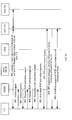
- FIG. 3 is a signaling diagram of a procedure in which a user equipment performs IMS registration and sets up a SIP session in a PS domain before initiating a reverse SRVCC handover in a method for processing reverse single radio voice call continuity according to an embodiment of the present invention.
- a UE that does not support DTM or UTMS mode and a first network element of the PS domain being an ATCF/ATGW are taken as examples to describe the specific process of performing, by the UE in advance in a PS domain network, IMS registration and SIP session setup.
- a preparation process performed in the PS domain network specifically includes the following steps:
- the UE that does not support DTM or UTMS mode is taken as an example for description, that is, the UE cannot support a CS domain voice bearer and a PS domain voice bearer at the same time. Therefore, the IMS registration, which is performed by the UE in the PS domain before the reverse SRVCC handover, needs to be performed before the UE initiates a voice call of a CS domain and sets up a CS domain voice session with a peer UE. In an actual application, the UE may perform the preparation operation in the PS domain immediately when being powered on.
- the performing, by the UE, registration in the PS domain network may specifically be divided into two processes: the first process is that the UE performs, on the SGSN device, the registration in the PS domain network, and the second process is that the UE performs IMS registration and then initiates a SIP voice call.
- the first registration process may specifically include step 300 to step 305.
- the UE may further carry, in the attach request, information about a codec type (CodeC) supported by default in the PS domain network. Based on the CodeC information, the SGSN may learn the codec type supported by the UE in the PS domain network.
- CodeC codec type
- the UE may further perform IMS registration on the SCC AS based on the registered information.
- the IMS registration procedure may specifically include the following steps:
- the SGSN may further send the IMS registration request to the ATCF through a gateway GPRS support node (Gateway GPRS Support Node, GGSN for short).
- GGSN Gateway GPRS Support Node
- Step 307 The ATCF anchors the IMS registration to itself.
- Step 308 The ATCF allocates STN-SR information for the UE, carries the STN-SR in the IMS registration request, and forwards the IMS registration request to the SCC AS through an interrogating/serving call session control function (Interrogating/Serving Call Session Control Function, I/S-CSCF for short).
- I/S-CSCF Interrogating/Serving Call Session Control Function
- Step 309 The SCC AS updates the STN-SR of the UE to an HSS.
- Step 310 The HSS updates the STN-SR of the UE to the SGSN.
- the UE may further initiate an IMS registration procedure to the SCC AS and further initiate a SIP session setup process to pre-establish a reserved VOIP voice bearer corresponding to the UE in the PS domain network through the process of setting up the SIP session with the SCC AS.
- the UE needs to anchor the IMS registration request to the ATCF network element first to initiate the SIP session setup through the ATCF.
- the anchor process may be implemented by sending, by the UE, the IMS registration request to the ATCF and anchoring, by the ATCF, the IMS registration process to ATCF itself after receiving the IMS registration request.
- the ATCF may further allocate, for the UE, an STN-SR identifier of the UE in the PS domain network, carry the STN-SR in the IMS registration request, and forward the IMS registration request to the SCC AS through the I/S-CSCF so that the SCC AS updates the STN-SR identifier, which is allocated to the UE, to the data base HSS and then to the SGSN.
- Step 311 The UE sends a SIP session setup request to the ATCF.
- Step 312 The ATCF anchors the SIP session to the ATGW so that the ATGW allocates, for the UE, first information for bearing a VOIP voice service.
- Step 313 The ATCF forwards the SIP session setup request to the SCC AS through the I/S-CSCF.
- the ATCF may further anchor the SIP session to the ATCF/ATGW when the UE sends the SIP session setup request to it.
- the ATGW allocates, for the UE, the IP address and/or information for bearing the VOIP voice service of the UE, that is, the first piece of information.
- the ATCF forwards the SIP session setup request to the SCC AS through the I/S-CSCF.
- the SCC AS completes UE context configuration and returns information configured for the UE to the ATCF through the I/S-CSCF.
- the ATCF may terminate the SIP session setup request message on the ATCF.
- the initiating, by the UE, the SIP session setup request does not aim to actually set up a SIP session with the peer UE.
- the pre-established SIP session connection may not actually function before the UE initiates a voice service handover from the CS domain network to the PS domain network, and may be used only for allocating corresponding resources for the UE in a core network of the PS domain network and does not transmit any data.
- the UE may quickly hand over, based on the preallocated resources, the voice service to the VOIP voice of the PS domain, and perform a subsequent access transfer procedure for the voice service. In this manner, a SIP session does not need to be initiated in the subsequent access transfer procedure to establish a VOIP voice bearer temporarily, which is equal to accelerating the subsequent access transfer procedure.
- the UE may carry reverse SRVCC indication information in the SIP session setup request sent by the UE through the ATCF, where the reverse SRVCC indication information is used to finally indicate to the SCC AS that the SIP session set up currently is used in the subsequent reverse SRVCC handover procedure, thereby indicating that, when setting up the SIP session for the UE according to the SIP session setup request, the SCC AS only needs to locally process the SIP session setup request message, does not need to initiate an actual voice call to the peer UE, and even when no data is transmitted on the reserved SIP session connection for a long period of time, does not need to proactively trigger the process of releasing information about resources of the UE.
- the carrying, by the UE, the reverse SRVCC indication information in the SIP session setup request sent to the SCC AS may specifically be implemented in the following two manners: the UE may separately carry a piece of indication information in the SIP session setup request, for example, rSRVCC indicator information; or the UE may also carry a special called number in the SIP session setup request sent to the SCC AS, so as to indicate that, when receiving the SIP session setup request that carries the called number, the SCC AS learns that the SIP session is used in the reverse SRVCC handover.
- the UE may further send another piece of indication information to the SGSN besides finally sending the reverse SRVCC indication information to the SCC AS.
- the indication information is used to indicate that the SGSN does not need to initiate an RAB establishment process after the SIP session is set up in the PS domain network for the UE.
- the actual function of establishing the SIP session connection for the UE is preparing for the subsequent reverse SRVCC handover process.
- the SIP session connection does not transmit any voice data of the UE.
- the SGSN does not need to initiate an actual RAB establishment process, thereby avoiding a waste of resources.
- the method for the UE to send the indication information to the SGSN reference may be made to the description in the preceding embodiment and no further description is provided here.
- the UE may further negotiate, with the SCC AS, the CodeC information of the UE in the PS domain network. After the negotiation is successful, the SCC AS carries the negotiated CodeC information in a SIP response message and returns the SIP response message to the UE.
- information used for identifying, for example, a destination IP address of service sending of the UE in the PS domain network may also be negotiated by the UE and the SCC AS in the signaling interaction process, and the negotiated IP address information is carried by the SCC AS in the SIP response message and returned to the UE together with the CodeC information.
- Step 314 The SCC AS returns a call response message to the ATCF through the I/S-CSCF, where the call response message may include UE-related configuration information, for example, a correlation-MSISDN (Correlation-MSISDN, C-MISDN for short).
- UE-related configuration information for example, a correlation-MSISDN (Correlation-MSISDN, C-MISDN for short).
- the SCC AS After processing the SIP session setup request sent by the UE, the SCC AS returns the call response message to the ATCF through the I/S-CSCF. Alternatively, in the returned call response message, the SCC AS may further return, to the ATCF, the C-MSISDN number that is allocated for the UE and corresponds to the SIP session set up for the UE, and allocate, for the UE, a special number, for example, an rSRVCC access transfer identifier (rSRVCC Access Transfer Update-Session Transfer Identifier, rSRVCC ATU-STI for short), and return the special number to the ATCF.
- the ATCF stores the special number and the C-MSISDN number that are returned by the SCC AS.
- the ATCF directly returns the call response message to the UE, where the call response message does not carry the stored information. In this case, a voice bearer is established between the UE and the ATGW.
- Step 315 The UE establishes a reserved VOIP voice bearer in the PS domain network with the SCC AS.
- the UE may further establish, with the SCC AS, the reserved VOIP voice bearer in the PS domain network, which specifically refers to that a PS media plane between the UE, the SGSN, an SGW, a PGW and the ATGW is established.
- the reserved VOIP voice bearer may be used in the subsequent reverse SRVCC handover process.
- the reserved VOIP voice bearer that is pre-established is used in the subsequent reverse SRVCC handover process and is in suspended state before the handover. By pre-establishing the suspended VOIP voice bearer, the UE does not need to establish a VOIP voice bearer when the UE actually initiates the reverse SRVCC handover process, thereby accelerating the voice service handover to the PS domain network.
- Step 316 The UE initiates a voice call of a CS domain to set up a CS domain voice session with the peer UE.
- the UE may initiate a voice call of the CS domain to the peer UE according to a regular CS domain voice session procedure to set up a CS domain voice session with the peer UE.
- the registration performed by the UE in the PS domain network may be completed after the UE sets up the CS domain voice session in the CS domain network. That is, the UE sets up a normal voice session in the CS domain network first, and then needed resources are allocated in the PS domain network for the UE. In this manner, the voice service is borne in the CS domain network and the situation that registration of a new voice service affects a voice service in the original CS domain network is avoided.
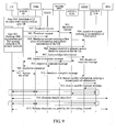
- FIG. 4 is a signaling diagram of a method for processing reverse single radio voice call continuity according to Embodiment 3 of the present invention.
- a reverse SRVCC handover process in this embodiment is performed based on the pre-registration of the UE described in the preceding embodiment and signaling diagram.
- a UE that does not support DTM or UTMS mode and a first network element of a PS domain being an ATCF/ATGW are taken as examples to describe the specific process of a reverse SRVCC handover performed by the UE.
- a process of establishing a forwarding channel between the ATCF/ATGW and an rSRVCC MSC may be controlled by an MME or be completed by proactively querying, by the rSRVCC MSC, related information from an HSS. Only the process of establishment controlled by the MME is described in detail in this embodiment, and the other process is described in detail in the following embodiment.
- the ATCF and the ATGW are generally deployed together. Therefore, in this embodiment, the first network element ATGW is described as the ATCF/ATGW, indicating that signaling messages sent by other network elements to the ATGW may be forwarded by the ATCF to the ATGW.
- the method includes the following steps:
- the UE Before performing the reverse SRVCC handover, the UE performs registration and establishes a SIP session connection in advance in the PS domain network so that the PS domain network preallocates information about reserved resources for the UE. Further, based on the preallocated information about resources, the UE may further pre-establish a reserved VOIP voice bearer for a voice service in the PS domain network.
- the UE that does not support DTM or UTMS mode is taken as an example for description.
- the pre-registration process performed by the UE in the PS domain network needs to be performed before the process of setting up a normal CS domain voice session, so as to avoid the situation that registration of a new voice service affects a voice service in the original CS domain network.
- Step 402 A radio network subsystem (Radio Network Subsystem, RNS for short)/base station system (Base Station System, BSS for short) sends a handover request to a serving MSC.
- RNS Radio Network Subsystem
- BSS Base Station System
- the UE does not support DTM or UTMS mode, that is, the UE only supports one type of voice bearer. Therefore, in the process of initiating, by the RNS/BSS, the reverse SRVCC handover, only a bearer of CS domain voice type needs to be handed over. Therefore, in this step, the RNS/BSS needs to send the handover request only to the serving MSC. However, it should be noted that if in this embodiment, the UE supports DTM or UMTS mode, in this step, the RNS/BSS needs to send the handover request to the serving MSC and an SGSN at the same time.
- the BSS/RNS may further carry reverse SRVCC indication information in the handover request when sending the handover request to the serving MSC, so as to notify, through the serving MSC, the MME or the rSRVCC MSC that the handover is rSRVCC.
- the MME may contact a home subscriber server (Home Subscriber Server, HSS for short) according to the indication information to acquire identifier information of a corresponding SGSN.
- Step 403 The serving MSC forwards the handover request to the rSRVCC MSC.
- Step 404 The rSRVCC MSC forwards the handover request to the MME.
- the serving MSC After receiving the handover request of the RNS/BSS, the serving MSC forwards the handover request (rSRVCC CS to PS request) to the rSRVCC MSC. In order to respond to the handover request, the rSRVCC MSC allocates, for the UE, second information such as an IP address and/or a port.
- Step 405 The MME sends an identifier query request to the HSS to acquire the identifier of an SGSN serving the UE.
- Step 406 The HSS returns the identifier of an SGSN corresponding to the UE to the MME.
- the MME After the MME receives the handover request forwarded by the rSRVCC MSC, in order to enable the rSRVCC MSC to address to the corresponding ATCF/ATGW to exchange IP address and/or port information with the ATCF/ATGW and thereby establish a forwarding channel, the MME first needs to acquire, from the data base HSS, the identifier of the SGSN corresponding to the UE, and thereby acquire, from the corresponding SGSN, STN-SR information and related voice bearer information of the UE in the PS domain network, so as to address to the corresponding ATCF/ATGW according to the STN-SR.
- the MME after receiving the handover request forwarded by the rSRVCC MSC, the MME sends the identifier query request message to the HSS, where the identifier query request message may specifically be a location update request or a request message of another type, and the identifier query request message carries the identifier of the UE to instruct the HSS to return the identifier of the SGSN which a specified UE belongs to.
- the HSS queries the specified UE in the local data base and returns the found identifier of the SGSN corresponding to the UE to the MME.
- the identifier request message sent by the MME to the HSS may further carry rSRVCC indicator information to notify the HSS that the current query is used in an rSRVCC handover operation.
- Step 407 The MME acquires, from the SGSN, context information of the UE.
- the MME After acquiring the identifier of the SGSN corresponding to the UE, the MME addresses to the corresponding SGSN and performs signaling interaction with the SGSN, so as to acquire, from the SGSN, the context information of the UE, where the context information includes the STN-SR information and CodeC information that are registered in the PS domain network by the UE.
- Step 408 The MME instructs an ENB to allocate access handover resources for the UE.
- Step 409 The ENB sends acknowledge information to the MME to acknowledge that allocation of the access handover resources is completed.
- the MME has acquired the context information of the UE.
- the MME may further instruct the ENB in the PS domain network to prepare access handover resources for the UE.
- the ENB sends an acknowledge message to the MME to notify that the allocation of the access handover resources prepared for the UE is completed.
- Step 410 The MME sends a handover response message to the rSRVCC MSC, where the handover response message carries the acquired context information of the UE.
- the MME may further returns the handover response message to the rSRVCC MSC, where the handover response message carries the context information of the UE acquired from the SGSN in step 407, that is, the STN-SR and CodeC information that are registered in the PS domain network by the UE in the pre-registration process.
- the context information of the UE is forwarded to the rSRVCC MSC by using the handover response message.
- the Codec information is optional.
- the rSRVCC MSC is capable of performing a corresponding encoding operation on uplink voice data when forwarding the uplink voice data of the UE to the ATGW and after establishing the forwarding channel with the ATGW, and then forwarding encoded uplink voice data to the UE.
- Step 411 The rSRVCC MSC returns the handover response message to the RNS/BSS through the serving MSC.
- the rSRVCC MSC may further forward the handover response message through the MSC, so as to notify the RNS/BSS that the allocation of the access handover resources prepared for the UE is completed.
- Step 412 The rSRVCC MSC sends a SIP message to the ATCF/ATGW, where the SIP message carries the second information allocated by the rSRVCC MSC.
- Step 413 The ATCF/ATGW returns a SIP response message to the rSRVCC MSC, where the SIP response message carries the first information allocated by the ATCF/ATGW.
- the rSRVCC MSC may directly address to the corresponding ATCF/ATGW according to the STN-SR information to exchange IP address and/or port information with the ATCF/ATGW, thereby establishing a forwarding channel with the ATCF/ATGW.
- Step 414 The RNS/BSS sends a handover command to the UE.
- Step 415 The UE accesses the ENB.
- Step 416 The ENB sends a handover complete message to the MME.
- the RNS/BSS sends the handover command to the UE to instruct the UE to perform the operation of accessing the PS domain network (EUTRAN).
- EUTRAN PS domain network
- the ENB After the procedure of access of the UE to the ENB is completed, the ENB sends the handover complete message to the MME to notify the MME that the access to the PS domain network is completed. After both the IP address and/or port information exchange between the rSVCC MSC and the ATCF/ATGW and the access of the UE to the ENB are completed, new voice bearer paths are established between the UE and the peer UE.
- Downlink voice data sent by the UE to the peer UE may be sent to the peer UE through the downlink voice bearer path "UE-ENB-SGW-PGW-ATGW-rSVCC MSC-Peer UE", and uplink voice data sent by the peer UE to the UE may be sent to the UE through the reverse bearer path "Peer UE-rSVCC MSC-ATGW-PGW-SGW-ENB-UE” (as shown by the dashed lines below step 416 in FIG. 4 ).
- the UE and the peer UE are also capable of performing voice data communication through the bearer paths without the need of interrupting the voice service, thereby ensuring good continuity of the voice service.
- the bearer paths are established on the basis that the UE completes the access to the PS domain network. Therefore, the voice service based on the current UE is further capable of achieving good quality of the voice service.
- Step 418 After the access transfer procedure is completed, release resources occupied by the forwarding channel.
- the ATCF/ATGW may further initiate the access transfer procedure.
- the access transfer procedure is performed on the basis that the UE is capable of performing a normal VOIP voice service with the peer UE. Therefore, the speed of the access transfer procedure does not affect the continuity of the voice service of the UE. Specifically, for the process of initiating the access transfer by the ATCF/ATGW, reference may be made to FIG. 5 .
- the UE does not perform the IMS registration procedure in the pre-registration procedure performed by the UE in the PS domain network, the UE needs to perform IMS registration in the PS domain network first before the ATCF/ATGW initiates the access transfer procedure.
- the UE may perform voice data communication with the peer UE by using new voice bearer paths established in the access transfer process, that is, perform the voice service with the peer UE through the downlink voice bearer path "UE-ENB-SGW-PGW-ATGW-Peer UE" and the uplink voice bearer path "Peer UE-ATGW-PGW-SGW-ENB-UE” (as shown by the dashed lines below step 417 in FIG. 4 ).
- the rSVCC MSC may control release of the resources occupied by the forwarding channel to actually complete the reverse SRVCC handover procedure.
- a resource releasing process may be initiated by the ATCF.
- a core network element in the PS domain network is to proactively trigger establishment of a VOIP voice bearer of the UE in the PS domain network.
- the process of establishing the VOIP voice bearer may be triggered by the SGSN, the MSC, the ATCF, or another core network element in the PS domain network immediately after step 402.
- the UE performs IMS registration and initiates SIP session setup in advance in the PS domain network so that the PS domain network preallocates information about bearer resources for the UE.
- the MME controls establishment of a forwarding channel of voice data between an rSRVCC MSC in the CS domain network and an ATGW in the PS domain network by using information about a reserved bearer, in which the information is preallocated by the PS domain network for the UE.
- the UE is capable of quickly transmitting voice data with a peer user equipment through the established forwarding channel without the need of waiting a long time before an access transfer procedure is completed. This ensures good performance of voice service continuity in the reverse SRVCC handover process.
- the forwarding channel is established on the basis that the UE completes the access to the PS domain network. Therefore, the voice service performed based on the forwarding channel is further capable of achieving good quality of the voice service.
- FIG. 5 is a signaling diagram of an access transfer procedure in a method for processing reverse single radio voice call continuity according to an embodiment of the present invention.
- a detailed process of exchanging IP address and/or port information by an rSRVCC MSC and an ATGW is also described in the signaling diagram in this embodiment.
- the process of exchanging port and/or port information by the rSRVCC MSC and the ATGW and the access transfer procedure initiated by the ATCF are specifically as follows:
- the rSRVCC MSC carries the IP address and/or port information allocated to the UE and the C-MSISDN number acquired in advance in the SIP message, and sends the SIP message to the ATCF.
- the C-MSISDN number is associated with the SIP session set up in advance for the UE.
- the ATCF may find, according to the C-MSISDN number, the SIP session corresponding to the UE.
- the ATCF After receiving the SIP message, the ATCF uses the C-MSISDN to associate with the session that needs to be transferred and then interacts with the ATGW. In this manner, a media plane is updated and the pre-established voice bearer is associated with a new bearer, that is, the new bearer between the rSRVCC MSC and the ATGW.
- Step 502 The ATGW returns a Configure ATGW Acknowledgment (Configure ATGW Acknowledgment) message to the ATCF, where the IP address and/or port information preallocated by the ATGW for the UE is sent to the ATCF.
- Configure ATGW Acknowledgment Configure ATGW Acknowledgment
- Step 503 The ATCF returns a SIP response message to the rSRVCC MSC, where the SIP response message carries the IP address and/or port information of the ATGW.
- Step 504 The ATCF sends an Access Transfer Update (Access Tranfer Update) message to the SCC AS.
- Access Transfer Update Access Tranfer Update
- Step 505 The SCC AS forwards the Access Transfer Update message to the peer UE.
- the ATCF After receiving a CS-PS access transfer message, the ATCF re-establishes a session with the SCC AS to notify the SCC AS that CS-PS access transfer occurs.
- the SCC AS locates a related session by using an rSRVCC ATU-STI, and a new session is set up between the ATCF and the SCC AS.
- the SCC AS associates the new session with the SIP session set up in advance by the UE in the registration process, where the association operation is generally implemented by using the C-MSISDN.
- the SCC AS updates the media plane of the peer UE to enable the peer UE to directly send voice data to the ATGW.
- the peer UE is capable of directly receiving voice data sent by the ATGW.
- Step 506 The peer UE returns an update response message to the SCC AS.
- Step 507 The SCC AS returns an Access Transfer Update response message to the ATCF.
- new voice bearer paths are established between the UE and the peer UE.
- the new voice bearer paths established after the access transfer are specifically the downlink voice bearer path "UE-ENB-SGW-PGW-ATGW-Peer UE" and the uplink voice bearer path "Peer UE-ATGW-PGW-SGW-ENB-UE".
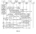
- FIG. 6 is a signaling diagram of a method for processing reverse single radio voice call continuity according to Embodiment 4 of the present invention.
- a reverse SRVCC handover process in this embodiment is performed based on the pre-registration of the UE described in the embodiment and signaling diagram illustrated in FIG. 3 .
- a UE that supports DTM or UTMS mode and a first network element of a PS domain being an ATCF/ATGW are taken as examples to describe the specific process of a reverse SRVCC handover performed by the UE. Only the process of controlling, by an MME, establishment of a forwarding channel between the ATCF/ATGW and an rSRVCC MSC is described in detail.
- the method includes the following steps:
- the UE that supports DTM or UTMS mode is taken as an example for description. Therefore, the pre-registration process performed by the UE in the PS domain network may be performed after the process of setting up a normal CS domain voice session without occurrence of the situation that registration of a new voice service affects a voice service in the original CS domain network.
- Step 602 An RNS/BSS sends a handover request to a serving MSC and an SGSN at the same time.
- Step 603 The serving MSC forwards the handover request to an rSRVCC MSC.
- Step 604 The rSRVCC MSC forwards the handover request to an MME.
- Step 605 The SGSN carries context information of the UE in the handover request, and forwards the handover request to the MME.
- the UE supports DTM or UMTS mode. Therefore, the MME does not need to send an identifier query request to an HSS to acquire, from the HSS and by using the location update request, the identifier of an SGSN corresponding to the UE, and thereby address to the SGSN.
- the SGSN proactively forwards the context information of the UE to the MME on the basis that the handover request sent by the RNS/BSS is received.
- the MME is capable of automatically acquiring the context information pre-registered in the PS domain network by the UE without the need of sending the identifier query request to the HSS.
- Step 606 The MME instructs an ENB to allocate access handover resources for the UE.
- Step 607 The ENB sends acknowledge information to the MME to acknowledge that allocation of the access handover resources is completed.
- the MME may instruct the ENB in the PS domain network to prepare access handover resources for the UE. After the resource allocation is completed, the ENB sends an acknowledge message to the MME to notify that the allocation of the access handover resources prepared for the UE is completed.
- Step 608 The MME sends a handover response message to the rSRVCC MSC, where the handover response message carries the context information of the UE.
- Step 609 The rSRVCC MSC sends a SIP message to the ATCF/ATGW, where the SIP message carries second information allocated by the rSRVCC MSC.
- Step 610 The ATCF/ATGW returns a SIP response message to the rSRVCC MSC, where the SIP response message carries first information allocated by the ATCF/ATGW.
- the rSRVCC MSC may directly address to the corresponding ATCF/ATGW according to the STN-SR information to exchange IP address and/or port information with the ATCF/ATGW, thereby establishing a forwarding channel with the ATCF/ATGW.
- Step 611 The rSRVCC MSC returns the handover response message to the RNS/BSS through the serving MSC.
- Step 612 The MME returns the handover response message to the RNS/BSS through the SGSN.
- the MME further returns the handover response message to the SGSN after learning that the ENB completes the allocation of the access handover resources for the UE, so that the SGSN forwards the handover response message to the RNS/BSS to notify the RNS/BSS that access handover resource has been allocated in the ENB for the UE.
- Step 613 The RNS/BSS sends a handover command to the UE.
- Step 614 The UE accesses the ENB.
- Step 615 The ENB sends a handover complete message to the MME.
- Step 616 The MME sends a bearer modify request to the ATCF/ATGW.
- Step 617 The ATCF/ATGW returns a bearer modify response message to the MME.
- new voice bearer paths are established between the UE and the peer UE.
- Downlink voice data sent by the UE to the peer UE may be sent to the peer UE through the downlink voice bearer path "UE-ENB-SGW-PGW-ATGW-rSVCC MSC-Peer UE”
- uplink voice data sent by the peer UE to the UE may be sent to the UE through the reverse bearer path "Peer UE-rSVCC MSC-ATGW-PGW-SGW-ENB-UE".
- the UE and the peer UE are also capable of performing voice data communication through the bearer paths without the need of interrupting the voice service, thereby ensuring good continuity of the voice service.
- the bearer paths are established on the basis that the UE completes the access to the PS domain network. Therefore, the voice service based on the current UE is further capable of achieving good quality of the voice service.
- Step 618 The ATCF/ATGW initiates the access transfer procedure.
- Step 619 After the access transfer procedure is completed, release resources occupied by the forwarding channel.
- the ATCF/ATGW may further initiate the access transfer procedure.
- the UE may perform voice data communication with the peer UE by using new voice bearer paths established in the access transfer process, that is, perform the voice service with the peer UE through the downlink voice bearer path "UE-ENB-SGW-PGW-ATGW-Peer UE" and the uplink voice bearer path "Peer UE-ATGW-PGW-SGW-ENB-UE".
- the rSVCC MSC may control release of the resources occupied by the forwarding channel to actually complete the reverse SRVCC handover procedure.
- the resource releasing process may be initiated by the ATCF.
- the UE before a UE hands over a voice service from a CS domain network to a PS domain network, the UE performs IMS registration and initiates SIP session setup in advance in the PS domain network so that the PS domain network preallocates information about bearer resources for the UE.
- the MME controls establishment of a forwarding channel of voice data between an rSRVCC MSC in the CS domain network and an ATGW in the PS domain network by using information about a reserved bearer, in which the information is preallocated by the PS domain network for the UE.
- the UE is capable of quickly transmitting voice data with a peer user equipment through the established forwarding channel without the need of waiting a long time before an access transfer procedure is completed. This ensures good performance of voice service continuity in the reverse SRVCC handover process.
- the forwarding channel is established on the basis that the UE completes the access to the PS domain network. Therefore, the voice service performed based on the forwarding channel is further capable of achieving good quality of the voice service.
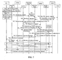
- FIG. 7 is a signaling diagram of a method for processing reverse single radio voice call continuity according to Embodiment 5 of the present invention.
- a reverse SRVCC handover process in this embodiment is performed based on the pre-registration of the UE described in the preceding embodiment and signaling diagram.
- a UE that does not support DTM or UTMS mode and a first network element of a PS domain being an ATCF/ATGW are taken as examples to describe the specific process of a reverse SRVCC handover performed by the UE.
- a process of establishing a forwarding channel between the ATCF/ATGW and an rSRVCC MSC may be controlled by an MME or be completed by proactively querying, by the rSRVCC MSC, related information from an HSS.
- the process of establishment implemented by proactively querying, by the rSRVCC MSC, related information from the HSS is described in detail in this embodiment.
- the ATCF and the ATGW are generally deployed together. Therefore, in this embodiment, the first network element ATGW is described as the ATCF/ATGW, indicating that signaling messages sent by other network elements to the ATGW may be forwarded by the ATCF to the ATGW.
- the method includes the following steps:
- the UE that does not support DTM or UTMS mode is taken as an example for description. Therefore, the pre-registration process performed by the UE in the PS domain network needs to be performed before the process of setting up a normal CS domain voice session to avoid the situation that registration of a new voice service affects a voice service in the original CS domain network.
- Step 702 An RNS/BSS sends a handover request to a serving MSC.
- the UE does not support DTM or UTMS mode, that is, the UE only supports one type of voice bearer. Therefore, in the process of initiating, by the RNS/BSS, the reverse SRVCC handover, only a bearer of CS domain voice type needs to be handed over. Therefore, in this step, the RNS/BSS needs to send the handover request only to the serving MSC.
- the BSS/RNS may further carry reverse SRVCC indication information in the handover request when sending the handover request to the serving MSC.
- the serving MSC forwards the handover request to the rSRVCC MSC.
- Step 704 The rSRVCC MSC sends an identifier query request to the HSS, where the identifier query request carries the identifier of the UE.
- Step 705 The HSS returns the identifier of an SGSN corresponding to the UE to the rSRVCC MSC.
- the rSRVCC MSC after receiving the handover request forwarded by the serving MSC, the rSRVCC MSC sends, to the HSS, the identifier query request carrying the identifier of the UE, to directly query and acquire, from the data base HSS, identifier information of the SGSN corresponding to the UE instead of acquiring the identifier of the SGSN through an MME.
- the identifier query request message may specifically be a location update request or a request message of another type.
- the identifier request message sent by the MME to the HSS may further carry rSRVCC indicator information to notify the HSS that the current query is used in the rSRVCC handover operation.
- Step 706 The rSRVCC MSC forwards the handover request to a specified SGSN.
- Step 707 The SGSN returns a response message to the rSRVCC MSC, where the response message carries context information of the UE.
- the rSRVCC MSC After acquiring the identifier of the SGSN corresponding to the UE, the rSRVCC MSC addresses to the corresponding SGSN and forwards the handover request to the SGSN, where the handover request may carry instruction information to instruct the SGSN to return the context information of the UE, including STN-SR information and CodeC information that are registered in the PS domain network by the UE.
- Step 708 The SGSN forwards the handover request to an MME.
- Step 709 The MME instructs an ENB to allocate access handover resources for the UE.
- Step 710 The ENB sends acknowledge information to the MME to acknowledge that allocation of the access handover resources is completed.
- the SGSN forwards the handover request message to the MME at the same time of returning the response message to the rSRVCC MSC.
- the MME may further instruct the ENB in the PS domain network to prepare access handover resources for the UE. After the resource allocation is completed, the ENB sends an acknowledge message to the MME to notify that the allocation of the access handover resources prepared for the UE is completed.
- Step 711 The rSRVCC MSC sends a SIP message to the ATCF/ATGW, where the SIP message carries second-information-allocated by the rSRVCC MSC.
- Step 712 The ATCF/ATGW returns a SIP response message to the rSRVCC MSC, where the SIP response message carries first information allocated by the ATCF/ATGW.
- the rSRVCC MSC acquires the context information of the UE. Because in the pre-registration process of the UE, the UE has anchored the IMS registration to the ATCF, the rSRVCC MSC may directly address to the corresponding ATCF/ATGW according to the STN-SR information in the context information to exchange IP address and/or port information with the ATCF/ATGW, thereby establishing the forwarding channel with the ATCF/ATGW.
- Step 713 The MME sends a handover response message to the rSRVCC MSC.
- Step 714 The rSRVCC MSC returns the handover response message to the RNS/BSS through the serving MSC.
- Step 715 The RNS/BSS sends a handover command to the UE.
- Step 716 The UE accesses the ENB.
- Step 717 The ENB sends a handover complete message to the MME.
- the RNS/BSS sends the handover command to the UE to instruct the UE to perform the operation of accessing the PS domain network (EUTRAN).
- the UE successfully accesses the ENB, that is, accesses the PS domain network, and completes the network access procedure.
- the ENB sends the handover complete message to the MME to notify the MME that the access to the PS domain network is completed.
- new voice bearer paths are established between the UE and the peer UE.
- Downlink voice data sent by the UE to the peer UE may be sent to the peer UE through the downlink voice bearer path "UE-ENB-SGW-PGW-ATW-rSVCC MSC-Peer UE”
- uplink voice data sent by the peer UE to the UE may be sent to the UE through the reverse bearer path "Peer UE-rSVCC MSC-ATGW-PGW-SGW-ENB-UE".
- the UE and the peer UE are also capable of performing voice data communication through the bearer paths without the need of interrupting the voice service, thereby ensuring good continuity of the voice service.
- the bearer paths are established on the basis that the UE completes the access to the PS domain network. Therefore, the voice service based on the current UE is further capable of achieving good quality of the voice service.
- Step 718 The ATCF/ATGW initiates the access transfer procedure.
- Step 719 After the access transfer procedure is completed, release resources occupied by the forwarding channel.
- the ATCF/ATGW may further initiate the access transfer procedure.
- the access transfer procedure is performed on the basis that the UE is capable of performing a normal VOIP voice service with the peer UE. Therefore, the speed of the access transfer procedure does not affect the continuity of the voice service of the UE. Specifically, for the process of initiating the access transfer by the ATCF/ATGW, reference may be made to FIG. 5 .
- the UE does not perform the IMS registration procedure in the pre-registration procedure performed by the UE in the PS domain network, the UE needs to perform IMS registration in the PS domain network first before the ATCF/ATGW initiates the access transfer procedure.
- the UE may perform voice data communication with the peer UE by using new voice bearer paths established in the access transfer process, that is, perform the voice service with the peer UE through the downlink voice bearer path "UE-ENB-SGW-PGW-ATGW-Peer UE" and the uplink voice bearer path "Peer UE-ATGW-PGW-SGW-ENB-UE".
- the rSVCC MSC may control release of the resources occupied by the forwarding channel to actually complete the reverse SRVCC handover procedure.
- the resource releasing process may be initiated by the ATCF.
- a core network element in the PS domain network is to proactively trigger establishment of a VOIP voice bearer of the UE in the PS domain network.
- the process of establishing the VOIP voice bearer may be triggered immediately after step 702 by the SGSN, the MSC, the ATCF, or another core network element in the PS domain network.
- the UE before a UE hands over a voice service from a CS domain network to a PS domain network, the UE performs IMS registration and initiates SIP session setup in advance in the PS domain network so that the PS domain network preallocates information about bearer resources for the UE.
- a forwarding channel of voice data is established between an rSRVCC MSC and an ATGW by using information about a reserved bearer, in which the information is preallocated by the PS domain network for the UE and by proactively querying, by the rSRVCC MSC in the CS domain network, related information from an HSS.
- the UE is capable of quickly transmitting voice data with a peer user equipment through the established forwarding channel without the need of waiting a long time before an access transfer procedure is completed. This ensures good performance of voice service continuity in the reverse SRVCC handover process.
- the forwarding channel is established on the basis that the UE completes the access to the PS domain network. Therefore, the voice service performed based on the forwarding channel is further capable of achieving good quality of the voice service.
- FIG. 8 is another signaling diagram of the procedure in which a user equipment performs IMS registration and sets up a SIP session in a PS domain before initiating a reverse SRVCC handover in a method for processing reverse single radio voice call continuity according to an embodiment of the present invention.
- a UE that supports DTM or UTMS mode and a first network element of the PS domain being a PGW are taken as examples to describe the specific process of performing, by the UE in advance in a PS domain network, IMS registration and SIP session setup.
- the procedure of performing, by the UE, registration and SIP session setup in the PS domain network before initiating a reverse SRVCC handover procedure specifically includes the following steps:
- the UE that supports DTM or UTMS mode is taken as an example for description and the UE is capable of supporting a CS domain voice bearer and a PS domain voice bearer at the same time. Therefore, the IMS registration and SIP session setup that are initiated in the PS domain by the UE before the reverse SRVCC handover may be performed on the basis that the UE initiates a voice call of a CS domain and establishes a CS domain voice session with the peer UE.
- the performing, by the UE in the PS domain network, the IMS registration and the SIP session setup after completing, according to a regular CS session process, setup of the CS session with the peer UE may specifically be divided into two processes.
- the first process is that the UE performs, on an SGSN device, the registration in the PS domain network.
- the process of registration in the PS domain network may specifically include the following steps:
- Steps 805 and 806 in which the UE performs, on the SGSN, the primary PDP activation procedure are optional.
- the UE may further carry, in the attach request, information about a codec type (CodeC) supported by default in the PS domain network.
- CodeC codec type
- the SGSN may learn the codec type supported by the UE in the PS domain network.
- the UE may further carry instruction information to instruct the SGSN to acquire, from the PGW of the PS domain network, first information about an IP address/and or a port.
- the SGSN instructs the PGW to allocate, for the UE, information about resources that the UE needs in the PS domain network and return the information about resources to the SGSN, where the first information is used for establishing a forwarding channel in the subsequent reverse SRVCC handover process.
- the information about the port allocated by the PGW for the UE may be a public port dedicated to establishing the forwarding channel in the reverse SRVCC handover. If the port is a dedicated public port, the information about the port allocated by the PGW for the UE may be directly configured on an MME or an rSRVCC MSC.
- the UE may further perform IMS registration on the SCC AS based on the registered information.
- the SCC AS may allocate unique STN-SR information for the UE.
- the UE may further initiate a SIP session setup process on the SCC AS.
- the SIP session setup process may specifically include the following steps:
- the UE may further initiate the SIP session setup process to the SCC AS, and pre-establish a reserved SIP session connection in the PS domain network through the process of setting up the SIP session with the SCC AS.
- the initiating, by the UE, the SIP session setup request does not aim to actually set up a SIP session with the peer UE.
- the pre-established SIP session connection may not actually function before the UE initiates a voice service handover from the CS domain network to the PS domain network, and may be used only for allocating corresponding resources for the UE in a core network of the PS domain network and does not transmit any data.
- the UE may quickly hand over the voice service to VOIP voice of the PS domain based on the preallocated resources and perform a subsequent access transfer procedure for the voice service. In this manner, a SIP session does not need to be initiated to establish a VOIP voice bearer temporarily in the subsequent access transfer process, which is equal to accelerating the subsequent access transfer procedure.
- the UE may carry reverse SRVCC indication information in the SIP session setup request sent by the UE to the SCC AS, where the reverse SRVCC indication information is used to indicate to the SCC AS that the currently established SIP session is used in the subsequent reverse SRVCC handover procedure, thereby indicating that the SCC AS does not need to initiate an actual voice call to the peer UE when setting up the SIP session for the UE according to the SIP session setup message, and does not proactively trigger the process of releasing information about resources of the UE even when no data is transmitted on the reserved SIP session connection for a long period of time.
- the carrying, by the UE, the reverse SRVCC indication information in the SIP session setup request sent to the SCC AS may specifically be implemented in the following two manners: the UE may carry a piece of indication information separately in the SIP session setup request, for example, rSRVCC indicator information; or the UE may also carry a special called number in the SIP session setup request sent to the SCC AS so that when receiving the SIP session setup request that carries the called number, the SCC AS learns that the SIP session is used in the reverse SRVCC handover.
- the UE may further send another piece of indication information to the SGSN besides finally sending the reverse SRVCC indication information to the SCC AS.
- the indication information is used to indicate that the SGSN does not initiate an RAB establishment process after the SIP session is set up in the PS domain network for the UE.
- the actual function of establishing the SIP session connection for the UE is preparing for the subsequent reverse SRVCC handover process.
- the SIP session connection does not transmit any voice data of the UE.
- the SGSN does not need to initiate an actual RAB establishment process, thereby avoiding a waste of resources.
- the method for the UE to send the indication information to the SGSN reference may be made to the description in the preceding embodiment and no further description is provided here.
- the UE may further negotiate, with the SCC AS, the CodeC information of the UE in the PS domain network. After the negotiation is successful, the SCC AS carries the negotiated CodeC information in a SIP response message and returns the SIP response message to the UE.
- information used for identifying, for example, a destination IP address of service sending of the UE in the PS domain network may also be negotiated by the UE and the SCC AS in the signaling interaction process, and the negotiated IP address information is carried by the SCC AS in the SIP response message and returned to the UE together with the CodeC information.
- Step 809 The UE establishes a reserved VOIP voice bearer in the PS domain network.
- the UE may further pre-establish, in the PS domain network, the reserved VOIP voice bearer with the SCC AS for bearing a VOIP voice service of the UE. That is, information about a reserved bearer used for the VOIP voice service is further allocated for the UE in a core network element of the PS domain network.
- the reserved VOIP voice bearer that is pre-established is used in the subsequent reverse SRVCC handover process and is in suspended state before the handover. By pre-establishing the suspended VOIP voice bearer, the UE does not need to establish a VOIP voice bearer temporarily when the UE actually initiates the reverse SRVCC handover process, thereby accelerating the voice service handover to the PS domain network.
- the IMS registration performed by the UE in the PS domain network needs to be completed before the UE sets up the CS domain voice session in the CS domain network. That is, needed resources are allocated for the UE in the PS domain network first, and then the UE sets up a normal voice session in the CS domain network.
- the voice service is borne in the CS domain network and the situation that registration of a new voice service affects a voice service in the original CS domain network is avoided.
- FIG. 9 is a signaling diagram of a method for processing reverse single radio voice call continuity according to Embodiment 6 of the present invention.
- a UE that supports DTM or UTMS mode and a first network element of a PS domain being a PGW are taken as examples to describe the specific process of a reverse SRVCC handover performed by the UE.
- the method includes the following steps:
- the UE Before performing the reverse SRVCC handover, the UE performs registration and establishes a SIP session connection in advance in the PS domain network so that the PS domain network preallocates information about reserved resources for the UE. Further, based on the preallocated information about resources, the UE may further pre-establish a reserved VOIP voice bearer in the PS domain network for a voice service.
- Step 902 An RNS/BSS sends a handover request to a serving MSC and an SGSN at the same time.
- the UE supports DTM or UTMS mode, that is, supports the two types of voice bearers at the same time. Therefore, in the process of initiating, by the RNS/BSS, the reverse SRVCC handover, the RNS/BSS needs to hand over the two types of bearers at the same time, which specifically refers to that handovers of a CS voice service and a PS voice service are performed at the same time. Therefore, in this step, the RNS/BSS needs to send the handover request to the MSC and the SGSN at the same time. It should be noted that if in this embodiment, the UE does not support DTM mode, in this step, the RNS/BSS only needs to send the handover request to the MSC.
- Step 903 The serving MSC forwards the handover request to an rSRVCC MSC.
- Step 904 The rSRVCC MSC allocates second information for the UE, where the second piece of information is carried in the handover request and forwarded to an MME.
- the serving MSC after receiving the handover request of the RNS/BSS, forwards the handover request to the rSRVCC MSC to instruct the rSRVCC MSC to allocate, for the UE, the second information about an IP address and/or a port.
- the rSRVCC MSC learns, according to the handover request, that the UE needs to hand over the voice service to the PS domain network at present. Therefore, the rSRVCC MSC responds to the handover request, allocates the IP address and/or port information for the UE, carries the allocated second information about the IP address and/or port in the handover request, and forwards the handover request to the MME.
- Step 905 The SGSN carries first information preallocated by the PGW and context information of the UE in the handover request, and forwards the handover request to the MME.
- the SGSN After receiving the handover request of the RNS/RSS, the SGSN forwards the handover request to the MME.
- the SGSN further carries, in the handover request, the first information about the IP address and/or port acquired from the first network element PGW and the context information, for example, STN-SR and CodeC information, registered in the PS domain network by the UE in the IMS registration process that is performed in advance by the UE in the PS domain network, and then forwards the handover request to the MME.
- the SGSN cannot proactively forward the first information and the context information of the UE to the MME when not receiving the handover request sent by the RNS/BSS.
- the MME sends, to an HSS, a location update request or another request message carrying the identifier of the UE, so as to acquire the preceding information from the SGSN.
- the HSS is capable of finding the identifier of the corresponding SGSN according to the identifier of the UE in the location update request and returning the identifier of the SGSN to the MME.
- the MME acquires, from the corresponding SGSN, the context information of the UE and the first information.
- Step 906 The MME instructs an ENB to allocate access handover resources for the UE.
- Step 907 The ENB sends acknowledge information to the MME to acknowledge that allocation of the access handover resources is completed.
- the MME may instruct the ENB in the PS domain network to prepare access handover resources for the UE. After the resource allocation is completed, the ENB sends an acknowledge message to the MME to notify that the allocation of the access handover resources prepared for the UE is completed.
- Step 908 The MME sends a handover response message to the rSRVCC MSC, where the handover response message carries the first information allocated by the PGW and the context information of the UE.
- the MME After learning that the ENB completes the allocation of the access handover resources for the UE, the MME returns the handover response message to the MGW, where the handover response message carries the first bearer information that is allocated by the PGW to a forwarding channel and the CodeC information registered in the PS domain network by the UE in the pre-registration process, which are acquired from the SGSN in step 905, so as to forward the first information that is allocated by the PGW to the second network element rSRVCC MSC, which is equal to notifying the rSRVCC MSC of the IP address and/or port information of the first network element PGW.
- the rSRVCC MSC may accurately transmit the uplink voice data to the first network element PGW according to the IP address and/or port information, so as to transmit the uplink voice data to the UE.
- the rSRVCC MSC is also capable of performing, based on the CodeC information registered in the PS domain network by the UE, a corresponding encoding operation on the uplink voice data before forwarding the uplink voice data of the UE to the PGW, and then forwarding the encoded uplink voice data to the UE.
- Step 909 The rSRVCC MSC returns the handover response message to the RNS/BSS through the serving MSC.
- the rSRVCC MSC After receiving the handover response message sent by the MME, the rSRVCC MSC stores the bearer information carried in the message, and further, the rSRVCC MSC forwards the handover response message to the RNS/BSS through the serving MSC to complete the procedure of CS voice handover to the PS domain.
- Step 910 The MME returns the handover response message to the RNS/BSS through the SGSN.
- the MME further returns the handover response message to the SGSN after learning that the ENB completes the allocation of the access handover resources for the UE, so that the SGSN forwards the handover response message to the RNS/BSS to notify the RNS/BSS that access handover resource information has been allocated in the ENB for the UE.
- Step 911 The RNS/BSS sends a handover command to the UE.
- Step 912 The UE accesses the ENB.
- Step 913 The ENB sends a handover complete message to the MME.
- the RNS/BSS After receiving the handover response message, the RNS/BSS sends the handover command to the UE to instruct the UE to perform the operation of accessing the PS domain network.
- the UE successfully accesses the ENB, that is, accesses the PS domain network, and completes the network access procedure.
- the ENB After the procedure of access of the UE to the ENB is completed, the ENB sends the handover complete message to the MME to notify the MME that the access to the PS domain network is completed.
- Step 914 The MME sends a bearer modify request to the PGW, carrying the second information allocated by the rSRVCC MSC for the UE.
- Step 915 The PGW returns a bearer modify response message to the MME.
- the MME After receiving the handover complete message, the MME sends the bearer modify request to the first network element PGW in the PS domain network, where the bearer modify request carries the second information acquired from the second network element rSRVCC MSC in step 904, that is, the MME enables, on the PGW, a bearer path for the voice service of the UE to point to the rSRVCC MSC and forwards, to the PGW, the IP address and/or port information allocated by the rSRVCC MSC for the UE. In this manner, the PGW enables the voice bearer path, which should originally point to the peer UE, to point to the rSRVCC MSC, thereby establishing a forwarding channel between the PGW and the rSRVCC MSC.
- the PGW when receiving, through the ENB, downlink voice data sent by the UE to the peer UE, the PGW is capable of accurately forwarding the downlink voice data to the rSRVCC MSC and then sending to the peer UE according to the IP address and/or port information allocated by the rSRVCC MSC for the VOIP voice bearer of the UE.
- the rSRVCC MSC is also capable of performing a corresponding decoding operation on the downlink voice data before sending the downlink voice data to the peer UE, and then forwarding the decoded downlink voice data to the peer UE.
- Downlink voice data sent by the UE to the peer UE may be sent to the peer UE through the downlink voice bearer path "UE-ENB-SGW-PGW-rSRVCC MSC-Serving MSC-Peer UE", and uplink voice data sent by the peer UE to the UE may be sent to the UE through the reverse bearer path "Peer UE-Serving MSC-rSVCC MSC-PGW-SGW-ENB-UE" (as shown by the dashed lines below step 915 in FIG. 9 ).
- the UE and the peer UE are also capable of performing voice data communication through the bearer paths without the need of interrupting the voice service, thereby ensuring good continuity of the voice service.
- the bearer paths are established on the basis that the UE completes the access to the PS domain network. Therefore, the voice service based on the current UE is further capable of achieving good quality of the voice service.
- the UE may be classified into two types: the type supporting DTM or UTMS mode and the type not supporting DTM or UTMS mode.
- the type supporting DTM or UTMS mode is taken as an example in this embodiment to describe the reverse SRVCC handover process, it should be understood that if the UE does not support DTM or UTMS mode, the difference between the reverse SRVCC handover process in this embodiment and that when the UE supports DTM mode lies in that:
- Step 916 The UE initiates the access transfer procedure.
- Step 917 After the access transfer procedure is completed, release resources occupied by the forwarding channel.
- the UE may further initiate the access transfer procedure.
- the access transfer procedure is performed on the basis that the UE is capable of performing a normal VOIP voice service with the peer UE. Therefore, the speed of the access transfer procedure does not affect the continuity of the voice service of the UE. It should be noted that if the UE does not perform the IMS registration procedure in the pre-registration process performed by the UE in the PS domain network, the UE needs to perform IMS registration in the PS domain network first before the UE initiates the access transfer procedure.
- the UE may perform voice data communication with the peer UE by using new voice bearer paths established in the access transfer process, that is, perform the voice service with the peer UE through the downlink voice bearer path "UE-ENB-SGW-PGW-Peer UE" and the uplink voice bearer path "Peer UE-PGW-SGW-ENB-UE” (as shown by the dashed lines below step 916 in FIG. 9 ).
- the SCC AS may control release of the resources occupied by the forwarding channel to actually complete the reverse SRVCC handover procedure.
- the resource releasing process may be initiated by an interworking solution function (Interworking Solution Function, IWS).
- IWS Interworking Solution Function
- the IWS sends resource release indication information to the MME through the MSC so that the MME controls release of all resources of the VOIP bearer.
- the UE before a UE hands over a voice service from a CS domain network to a PS domain network, the UE performs IMS registration and initiates SIP session setup in advance in the PS domain network so that the PS domain network preallocates information about bearer resources for the UE.
- the MME controls establishment of a forwarding channel between an rSRVCC MSC and a PGW by using information about a reserved bearer, in which the information is preallocated by the PS domain network for the UE.
- the UE is capable of quickly transmitting voice data with a peer user equipment through the established forwarding channel without the need of waiting a long time before an access transfer procedure is completed. This ensures good performance of voice service continuity in the reverse SRVCC handover process.
- the forwarding channel is established on the basis that the UE completes the access to the PS domain network. Therefore, the voice service performed based on the forwarding channel is further capable of achieving good quality of the voice service.
- the program may be stored in a computer readable storage medium.
- the storage medium includes: any medium that may store program codes, such as a ROM, a RAM, a magnetic disk, or an optical disk.
- FIG. 10 is a schematic structural diagram of a user equipment according to Embodiment 1 of the present invention.
- the user equipment in this embodiment includes at least a resource information configuring module 11.
- the resource information configuring module 11 is configured to: before the user equipment hands over a voice service from a CS domain network to a PS domain network, preconfigure, in the PS domain network, information about resources that the voice service handover needs, where the information about resources may be used in the process of handing over, by the user equipment, the voice service from the CS domain network to the PS domain network.
- a forwarding channel can be established between a first network element of the PS domain network and a second network element of the CS domain network by using the preconfigured information about resources, where the forwarding channel is configured to forward voice service data between the user equipment and a peer user equipment after the user equipment accesses the PS domain network.
- a forwarding channel of voice data is pre-established between the CS domain network and the PS domain network by using information about a reserved bearer, in which the information is preallocated by the PS domain network for the UE.
- the UE is capable of quickly transmitting voice data with a peer user equipment through the forwarding channel without the need of waiting a long time before an access transfer procedure is completed. This ensures good performance of voice service continuity in the reverse SRVCC handover process.
- the forwarding channel is established on the basis that the UE completes the access to the PS domain network. Therefore, the voice service performed based on the forwarding channel is further capable of achieving good quality of the voice service.
- FIG. 11 is a schematic structural diagram of a user equipment according to Embodiment 2 of the present invention.
- a first network element in a PS domain network may specifically be a PGW or an ATGW
- a second network element in a CS domain network may specifically be an rSRVCC MSC.
- the resource information configuring module may specifically include an IMS registration unit 111 and a SIP session setup unit 112.
- the IMS registration unit 111 is configured to perform IMS registration in the PS domain network before the user equipment hands over a voice service from the CS domain network to the PS domain network; and the SIP session setup unit 112 is configured to set up a SIP session in the PS domain network before the user equipment hands over the voice service from the CS domain network to the PS domain network.
- the SIP session setup unit 112 may further includes a first indication subunit 1121, where the first indication subunit 1121 is configured to send rSRVCC indicator information to an SCC AS in the SIP session setup procedure performed by the SIP session setup module 112, where the rSRVCC indicator information is used to indicate to the SCC AS that the SIP session set up currently is used in a reverse SRVCC service handover, and therefore the SCC AS does not need to initiate a voice call to a peer user equipment, nor proactively trigger a procedure of releasing the preconfigured information about resources.
- the first indication subunit 1121 is configured to send rSRVCC indicator information to an SCC AS in the SIP session setup procedure performed by the SIP session setup module 112, where the rSRVCC indicator information is used to indicate to the SCC AS that the SIP session set up currently is used in a reverse SRVCC service handover, and therefore the SCC AS does not need to initiate a voice call to a peer user equipment, nor proactively trigger a procedure of
- the IMS registration unit 111 may further include a second indication subunit 1111, where the second indication subunit 1111 is configured to send indication information to an SGSN in the IMS registration procedure performed by the IMS registration module 111, where the indication information is used to indicate that the SGSN does not need to initiate an RAB establishment process before the user equipment initiates the voice service handover from the CS domain network to the PS domain network.
- the user equipment may include a VOIP voice bearer establishment module 12, where the VOIP voice bearer establishment module 12 is configured to pre-establish, in the PS domain network, a reserved VOIP voice bearer for the voice service handover after the SIP session setup unit 112 performs the SIP session setup procedure and before the user equipment initiates the voice service handover from the CS domain network to the PS domain network; or the VOIP voice bearer establishment module 12 is configured to establish, in the PS domain network, a VOIP voice bearer for the voice service handover after the user equipment initiates the voice service handover from the CS domain network to the PS domain network.
- the user equipment in this embodiment performs in advance IMS registration in the PS domain network before handing over a voice service from a CS domain network to a PS domain network domain so that the PS domain network preallocates bearer resources for the UE.
- a forwarding channel is pre-established between the CS domain network and the PS domain network by using information about a reserved bearer, in which the information is preallocated by the PS domain network for the UE.
- the UE is capable of quickly transmitting voice data with a peer user equipment through the forwarding channel without the need of waiting a long time before an access transfer procedure is completed. This ensures good performance of voice service continuity in the reverse SRVCC handover process.
- the forwarding channel is established on the basis that the UE completes the access to the PS domain network. Therefore, the voice service performed based on the forwarding channel is further capable of achieving good quality of the voice service.
- FIG. 12 is a schematic structural diagram of a mobility management entity according to Embodiment 1 of the present invention.
- the mobility management entity in this embodiment includes at least two modules: a receiving module 21 and a forwarding channel establishment module 22.
- the receiving module 21 is configured to receive a handover request, where the handover request is used to request a handover of a voice service of a UE from a CS domain network to a PS domain network; and the forwarding channel establishment module 22 is configured to: in the process of handing over, by the UE, the voice service from the CS domain network to the PS domain network, control establishment of a forwarding channel between a first network element of the PS domain network and a second network element of the CS domain network by using information about resources that the voice service handover needs, where the information is preconfigured by the UE in the PS domain network.
- the forwarding channel established under the control of the forwarding channel establishment module 22 is configured to forward voice service data between the UE and a peer UE after the UE
- the mobility management entity in this embodiment controls, in the process of handing over, by a UE, a voice service from a CS domain network to a PS domain network, establishment of a forwarding channel of voice data between the CS domain network and the PS domain network using information about resources that is preconfigured by the UE in the PS domain network before handing over the voice service from the CS domain to the PS domain.
- the UE is capable of quickly transmitting voice data with a peer user equipment through the forwarding channel without the need of waiting a long time before an access transfer procedure is completed.
- the forwarding channel is established on the basis that the UE completes the access to the PS domain network. Therefore, the voice service performed based on the forwarding channel is further capable of achieving good quality of the voice service.
- FIG. 13 is a schematic structural diagram of a mobility management entity according to Embodiment 2 of the present invention.
- a first network element in a PS domain network may specifically be an ATGW or a PGW
- a second network element in a CS domain network may specifically be an rSRVCC MSC.
- Information about resources that is preconfigured by a UE in the PS domain network using an IMS registration procedure and a SIP session setup procedure may include at least context information pre-registered in the PS domain network by the UE, where the context information includes at least STN-SR information.
- the forwarding channel establishment module 22 may further specifically include two subunits: a request receiving unit 221 and an information forwarding unit 222.
- the request receiving unit 221 is configured to receive a handover request forwarded by an SGSN, where the handover request carries the context information pre-registered by the UE; and the information forwarding unit 222 is configured to forward the context information to the rSRVCC MSC so that the rSRVCC MSC addresses to a corresponding ATGW according to the STN-SR information of the UE, and establishes a forwarding channel with the corresponding ATGW.
- the forwarding channel establishment module 22 may further specifically include three subunits: an identifier query unit 223, an information acquiring unit 224, and a request response unit 225.
- the identifier query unit 222 is configured to query in an HSS, according to the received handover request forwarded by the rSRVCC MSC, the identifier of an SGSN corresponding to the UE;
- the information acquiring unit 224 is configured to acquire, from the specified SGSN and according to the identifier of the SGSN found by the identifier query unit 223, the context information pre-registered by the UE;
- the request response unit 225 is configured to carry, in a handover response message, the STN-SR information in the context information acquired by the information acquiring unit 224, and return the handover response message to the rSRVCC MSC so that the rSRVCC MSC addresses to a corresponding ATGW according to the STN-SR information and establish a forwarding channel with the corresponding ATGW.
- the forwarding channel establishment 22 may further specifically include an information acquiring and forwarding unit 226.
- the information acquiring and forwarding unit 226 is configured to acquire, from the PGW and the rSRVCC MSC respectively, IP address and/or port information allocated by the PGW and the rSRVCC MSC to the UE, and enable the respectively acquired IP address and/or port information to be exchanged between the PGW and the rSRVCC MSC so that a forwarding channel is established between the PGW and the rSRVCC MSC.
- the mobility management entity controls, in the process of handing over, by a UE, a voice service from a CS domain network to a PS domain network, establishment of a forwarding channel of voice data between the CS domain network and the PS domain network by using information about resources that is configured by the UE that performs IMS registration in the PS domain network before handing over the voice service from the CS domain network to the PS domain network.
- the UE is capable of quickly transmitting voice data with a peer user equipment through the forwarding channel without the need of waiting a long time before an access transfer procedure is completed.
- the forwarding channel is established on the basis that the UE completes the access to the PS domain network. Therefore, the voice service performed based on the forwarding channel is further capable of achieving good quality of the voice service.
- FIG. 14 is a schematic structural diagram of a system for processing reverse single radio voice call continuity according to an embodiment of the present invention.
- the system for processing reverse single radio voice call continuity in this embodiment includes at least a user equipment 1, a first network element 2, and a second network element 3.
- the user equipment 1 is used to preconfigure, in a PS domain network, information about resources before handing over a voice service from a CS domain network to a PS domain network;
- the first network element 2 is located in the PS domain network
- the second network element 3 is located in the CS domain network
- the first network element 2 may specifically be a PGW or ATGW device in the PS domain network
- the second network element 3 may specifically be an rSRVCC MSC device in the CS domain network.
- a forwarding channel may be established between the first network element 2 and the second network element 3 by using the information about resources that is preconfigured by the user equipment 1, where the forwarding channel is configured to forward voice service data between the user equipment 1 and a peer user equipment after the user equipment 1 accesses the PS domain network.
- the UE before a UE hands over a voice service from a CS domain network to a PS domain network, the UE performs IMS registration and initiates SIP session setup in advance in the PS domain network so that the PS domain network preallocates information about bearer resources for the UE.
- a forwarding channel of voice data is established between the CS domain network and the PS domain network by using information about a reserved bearer, in which the information is preallocated by the PS domain network for the UE.
- the UE is capable of quickly transmitting voice data with a peer user equipment through the established forwarding channel without the need of waiting a long time before an access transfer procedure is completed. This ensures good performance of voice service continuity in the reverse SRVCC handover procedure.
- the forwarding channel is established on the basis that the UE completes the access to the PS domain network. Therefore, the voice service performed based on the forwarding channel is further capable of achieving good quality of the voice service.
- the system for processing reverse single radio voice call continuity in this embodiment may further include a mobility management entity 4.
- the mobility management entity 4 is configured to: in the process of handing over, by the user equipment 1, the voice service from the CS domain network to the PS domain network, control establishment of the forwarding channel between the first network element 2 and the second network element 3 by using the information about resources that is preconfigured by the user equipment 1.
- the mobility management entity 4 is configured to: in the process of handing over, by the user equipment 1, the voice service from the CS domain network to the PS domain network, control establishment of the forwarding channel between the first network element 2 and the second network element 3 by using the information about resources that is preconfigured by the user equipment 1.
Landscapes
- Engineering & Computer Science (AREA)
- Computer Networks & Wireless Communication (AREA)
- Signal Processing (AREA)
- Multimedia (AREA)
- Mobile Radio Communication Systems (AREA)
Claims (10)
- Verfahren zur Verarbeitung einer Einzel-Funksprachruf-Rückwärtsverbindungskontinuität, wobei das Verfahren Folgendes umfasst:Vorkonfigurieren von Informationen über Betriebsmittel, die für eine Sprachdienstgesprächsumschaltung notwendig sind, in dem paketvermittelten Domänennetz und durch ein Teilnehmergerät, während oder vor der Gesprächsumschaltung eines Sprachdienstes von einem leitungsvermittelten Domänennetz zu einem paketvermittelten Domänennetz (100);dadurch gekennzeichnet, dass das Verfahren ferner Folgendes umfasst:Aufbauen eines Weiterleitungskanals zwischen einem ersten Netzelement des paketvermittelten Domänennetzes und einem zweiten Netzelement des leitungsvermittelten Domänennetzes in dem Prozess der Gesprächsumschaltung des Sprachdienstes von dem leitungsvermittelten Domänennetz zu dem paketvermittelten Domänennetz durch das Teilnehmergerät, wobei der Weiterleitungskanal dafür konfiguriert ist, Sprachdienstdaten zwischen dem Teilnehmergerät und einem Peer-Teilnehmergerät zu senden, nachdem das Teilnehmergerät auf das paketvermittelte Domänennetz zugreift (101);wobei das erste Netzelement ein Zugriffsübertragungs-"Gateway" ATCF/ATGW ist und wobei das zweite Netzelement eine Mobilfunkvermittlungsstelle ist, die einen Einzel-Funksprachruf-Rückwärtsverbindungskontinuitätsdienst unterstützt.
- Verfahren zur Verarbeitung einer Einzel-Funksprachruf-Rückwärtsverbindungskontinuität nach Anspruch 1, wobei das Aufbauen eines Weiterleitungskanals zwischen einem ersten Netzelement des paketvermittelten Domänennetzes und einem zweiten Netzelement des leitungsvermittelten Domänennetzes unter Verwendung der vorkonfigurierten Informationen über Betriebsmittel spezifisch Folgendes umfasst:Steuern des Aufbauens des Weiterleitungskanals zwischen dem ersten Netzelement des paketvermittelten Domänennetzes und dem zweiten Netzelement des leitungsvermittelten Domänennetzes durch eine Mobilitätsmanagemententität MME unter Verwendung der vorkonfigurierten Informationen über Betriebsmittel.
- Verfahren zur Verarbeitung einer Einzel-Funksprachruf-Rückwärtsverbindungskontinuität nach Anspruch 2, wobei:die Informationen über Betriebsmittel wenigstens Kontextinformationen umfassen, die durch das Teilnehmergerät in dem paketvermittelten Domänennetz im Voraus registriert werden, und die Kontextinformationen wenigstens Informationen über eine Sitzungsübertragungsnummer für den Sprachruf-Rückwärtsverbindungskontinuitätsdienst STN-SR umfassen; unddas Steuern des Aufbauens des Weiterleitungskanals zwischen dem ersten Netzelement des paketvermittelten Domänennetzes und dem zweiten Netzelement des leitungsvermittelten Domänennetzes durch eine MME unter Verwendung der vorkonfigurierten Informationen über Betriebsmittel, falls das erste Netzelement das ATCF/ATGW ist und das Teilnehmergerät die Doppelübertragungsbetriebsart DTM oder die Betriebsart des universellen Mobilkommunikationssystems UMTS unterstützt, spezifisch Folgendes umfasst:Empfangen einer durch einen bedienenden GPRS-Unterstützungsknoten weitergeleiteten Gesprächsumschaltungsanforderung durch die MME, wobei die Gesprächsumschaltungsanforderung die durch das Teilnehmergerät im Voraus registrierten Kontextinformationen übermittelt; undWeiterleiten der Kontextinformationen an die Mobilfunkvermittlungsstelle durch die MME, so dass die Mobilfunkvermittlungsstelle in Übereinstimmung mit STN-SR-Informationen in den Kontextinformationen an ein entsprechendes ATCF/ATGW adressiert und den Weiterleitungskanal mit dem entsprechenden ATCF/ATGW aufbaut.
- Verfahren zur Verarbeitung einer Einzel-Funksprachruf-Rückwärtsverbindungskontinuität nach Anspruch 2, wobei:die Informationen über Betriebsmittel wenigstens Kontextinformationen umfassen, die in dem paketvermittelten Domänennetz durch das Teilnehmergerät im Voraus registriert werden, und wobei die Kontextinformationen wenigstens STN-SR-Informationen umfassen; unddas Steuern des Aufbauens des Weiterleitungskanals zwischen dem ersten Netzelement des paketvermittelten Domänennetzes und dem zweiten Netzelement des leitungsvermittelten Domänennetzes durch die MME unter Verwendung der vorkonfigurierten Informationen über Betriebsmittel, falls das erste Netzelement das ATCF/ATGW ist und das Teilnehmergerät die DTM- oder die UMTS-Betriebsart nicht unterstützt, spezifisch Folgendes umfasst:Abfragen einer Kennung eines dem Teilnehmergerät entsprechenden bedienenden GPRS-Unterstützungsknotens in einem "Home"-Teilnehmer-"Server" HSS durch die MME und in Übereinstimmung mit einer durch die Mobilfunkvermittlungsstelle weitergeleiteten empfangenen Gesprächsumschaltungsanforderung;Erfassen der durch das Teilnehmergerät im Voraus registrierten Kontextinformationen von dem spezifizierten bedienenden GPRS-Unterstützungsknoten durch die MME und in Übereinstimmung mit der ermittelten Kennung des bedienenden GPRS-Unterstützungsknotens; undÜbermitteln der STN-SR-Informationen, die in den Kontextinformationen sind, in einer Gesprächsumschaltungs-Antwortnachricht durch die MME; und Zurückgeben der Gesprächsumschaltungs-Antwortnachricht an die Mobilfunkvermittlungsstelle,so dass die Mobilfunkvermittlungsstelle in Übereinstimmung mit den STN-SR-Informationen in den Kontextinformationen an das entsprechende ATCF/ATGW adressiert und den Gesprächsumschaltungskanal mit dem entsprechenden ATCF/ATGW aufbaut.
- Verfahren zur Verarbeitung einer Einzel-Funksprachruf-Rückwärtsverbindungskontinuität nach Anspruch 1, wobei:die Informationen über Betriebsmittel wenigstens Kontextinformationen umfassen, die in dem paketvermittelten Domänennetz durch das Teilnehmergerät im Voraus registriert werden, und die Kontextinformationen wenigstens STN-SR-Informationen umfassen; undwobei das Aufbauen eines Weiterleitungskanals zwischen einem ersten Netzelement des paketvermittelten Domänennetzes und einem zweiten Netzelement des leitungsvermittelten Domänennetzes unter Verwendung der vorkonfigurierten Informationen über Betriebsmittel, falls das erste Netzelement das ATCF/ATGW ist und falls das Teilnehmergerät die DTM- oder die UMTS-Betriebsart nicht unterstützt, spezifisch Folgendes umfasst:Abfragen einer Kennung des dem Teilnehmergerät entsprechenden bedienenden GPRS-Unterstützungsknotens in einem HSS durch die Mobilfunkvermittlungsstelle nach Empfang einer Gesprächsumschaltungsanforderung;Weiterleiten der Gesprächsumschaltungsanforderung an die MME über einen spezifizierten bedienenden GPRS-Unterstützungsknoten und Erfassen der durch das Teilnehmergerät im Voraus registrierten Kontextinformationen von dem spezifizierten GPRS-Unterstützungsknoten durch die Mobilfunkvermittlungsstelle und in Übereinstimmung mit der ermittelten Kennung des bedienenden GPRS-Unterstützungsknotens; undAdressieren an ein entsprechendes ATCF/ATGW in Übereinstimmung mit den STN-SR-Informationen in den Kontextinformationen und Aufbauen des Weiterleitungskanals mit dem entsprechenden ATCF/ATGW durch die Mobilfunkvermittlungsstelle.
- Verfahren zur Verarbeitung einer Einzel-Funksprachruf-Rückwärtsverbindungskontinuität nach einem der Ansprüche 1-5, wobei das Verfahren ferner Folgendes umfasst:Initiieren einer Zugriffsübertragungsprozedur nach der Gesprächsumschaltung über das Teilnehmergerät zu dem paketvermittelten Domänennetz durch ein Netz und Senden von Sprachdaten mit dem Peer-Teilnehmergerät unter Verwendung des paketvermittelten Domänennetzes und des zweiten Netzelements der leitungsvermittelten Domäne durch das Teilnehmergerät.
- Mobilitätsmanagemententität (4), die Folgendes umfasst:ein Empfangsmodul (21), das dafür konfiguriert ist, eine Gesprächsumschaltungsanforderung zu empfangen, wobei die Gesprächsumschaltungsanforderung verwendet wird, um eine Gesprächsumschaltung eines Sprachdienstes eines Teilnehmergeräts (1) von einem leitungsvermittelten Domänennetz zu einem paketvermittelten Domänennetz anzufordern;dadurch gekennzeichnet, dass die Mobilitätsmanagemententität (4) ferner Folgendes umfasst:ein Weiterleitungskanal-Aufbaumodul (22), das zu Folgendem konfiguriert ist: Steuern des Aufbaus eines Weiterleitungskanals zwischen einem ersten Netzelement (2) des paketvermittelten Domänennetzes und einem zweiten Netzelement (2) des leitungsvermittelten Domänennetzes in Übereinstimmung mit der Gesprächsumschaltungsanforderung und unter Verwendung von Informationen über Betriebsmittel, die für die Sprachdienstgesprächsumschaltung notwendig sind, die in dem paketvermittelten Domänennetz durch das Teilnehmergerät (1) vorkonfiguriert werden, in dem Prozess der Gesprächsumschaltung des Sprachdienstes von dem leitungsvermittelten Domänennetz zu dem paketvermittelten Domänennetz durch das Teilnehmergerät (1), wobei der Weiterleitungskanal dafür konfiguriert ist, Sprachdienstdaten zwischen dem Teilnehmergerät (1) und einem Peer-Teilnehmergerät weiterzuleiten, nachdem das Teilnehmergerät (1) auf das paketvermittelte Domänennetz zugreift;wobei das erste Netzelement ein Zugriffsübertragungs-"Gateway" ATCF/ATGW ist und wobei das zweite Netzelement eine Mobilfunkvermittlungsstelle ist, die einen Einzel-Funksprachruf-Rückwärtsverbindungskontinuitätsdienst unterstützt.
- Mobilitätsmanagemententität nach Anspruch 7, wobei:die Informationen über Betriebsmittel wenigstens Kontextinformationen, die durch das Teilnehmergerät in dem paketvermittelten Domänennetz im Voraus registriert worden sind, umfassen und die Kontextinformationen wenigstens Informationen über eine Sitzungsübertragungsnummer für den Sprachruf-Rückwärtsverbindungskontinuitätsdienst STN-SR umfassen; undwobei das Weiterleitungskanal-Aufbaumodul, falls das erste Netzelement das ATCF/ATGW ist und falls das Teilnehmergerät die Doppelübertragungsbetriebsart DTM oder die Betriebsart des universellen Mobiltelekommunikationssystems UMTS unterstützt, spezifisch Folgendes umfasst:eine Anforderungsempfangseinheit, die dafür konfiguriert ist, die durch einen bedienenden GPRS-Unterstützungsknoten weitergeleitete Gesprächsumschaltungsanforderung zu empfangen, wobei die Gesprächsumschaltungsanforderung die durch das UE im Voraus registrierten Kontextinformationen übermittelt; undeine Informationsweiterleitungseinheit, die dafür konfiguriert ist, die Kontextinformationen an die Mobilfunkvermittlungsstelle weiterzuleiten, so dass die Mobilfunkvermittlungsstelle Informationen in den Kontextinformationen in Übereinstimmung mit dem STN-SR an ein entsprechendes ATCF/ATGW adressiert und den Weiterleitungskanal mit dem entsprechenden ATCF/ATGW aufbaut.
- Mobilitätsmanagemententität nach Anspruch 8, wobei:die Informationen über Betriebsmittel wenigstens Kontextinformationen umfassen, die durch das Teilnehmergerät in dem paketvermittelten Domänennetz im Voraus registriert werden, und die Kontextinformationen wenigstens Informationen über eine Sitzungsübertragungsnummer für den Sprachruf-Rückwärtsverbindungskontinuitätsdienst STN-SR umfassen; undwobei das Weiterleitungskanal-Aufbaumodul, falls das erste Netzelement das ATCF/ATGW ist und das Teilnehmergerät die DTM- oder die UMTS-Betriebsart nicht unterstützt, spezifisch Folgendes umfasst:eine Kennungsabfrageeinheit, die dafür konfiguriert ist, in einem "Home"-Teilnehmer-"Server" HSS und in Übereinstimmung mit der durch die Mobilfunkvermittlungsstelle weitergeleiteten empfangenen Gesprächsumschaltungsanforderung eine Kennung eines dem Teilnehmergerät entsprechenden bedienenden GPRS-Unterstützungsknotens abzufragen;eine Informationserfassungseinheit, die zu Folgendem konfiguriert ist: Erfassen der durch das Teilnehmergerät im Voraus registrierten Kontextinformationen in Übereinstimmung mit der ermittelten Kennung des bedienenden GPRS-Unterstützungsknotens von dem spezifizierten bedienenden GPRS-Unterstützungsknoten; undeine Anforderungsantworteinheit, die dafür konfiguriert ist, die STN-SR-Informationen in den Kontextinformationen in einer Gesprächsumschaltungs-Antwortnachricht zu übermitteln und die Gesprächsumschaltungs-Antwortnachricht an die Mobilfunkvermittlungsstelle zurückzugeben, so dass die Mobilfunkvermittlungsstelle in Übereinstimmung mit den STN-SR-Informationen zu einem entsprechenden ATCF/ATGW adressiert und den Weiterleitungskanal mit dem entsprechenden ATCF/ATGW aufbaut.
- System zur Verarbeitung einer Einzel-Funksprachruf-Rückwärtsverbindungskontinuität, wobei das System ein Teilnehmergerät (1), ein erstes Netzelement (2), ein zweites Netzelement (3) und eine Mobilitätsmanagemententität (4) umfasst, wobei:das Teilnehmergerät (1) zu Folgendem konfiguriert ist: Vorkonfigurieren von Informationen über Betriebsmittel, die für die Sprachdienstgesprächsumschaltung notwendig sind, in dem paketvermittelten Domänennetz vor der Gesprächsumschaltung eines Sprachdienstes von dem leitungsvermittelten Domänennetz zu einem paketvermittelten Domänennetz; undwobei sich das erste Netzelement (2) in dem paketvermittelten Domänennetz befindet und das zweite Netzelement (3) in dem leitungsvermittelten Domänennetz befindet, dadurch gekennzeichnet, dassin dem Prozess der Gesprächsumschaltung des Sprachdienstes von dem leitungsvermittelten Domänennetz zu dem paketvermittelten Domänennetz durch das Teilnehmergerät (1) unter Verwendung der vorkonfigurierten Informationen über Betriebsmittel zwischen dem ersten Netzelement (2) des paketvermittelten Domänennetzes und dem zweiten Netzelement (3) des leitungsvermittelten Domänennetzes ein Weiterleitungskanal aufgebaut wird, wobei der Weiterleitungskanal dafür konfiguriert ist, Sprachdienstdaten zwischen dem Teilnehmergerät (1) und einem Peer-Teilnehmergerät weiterzuleiten, nachdem das Teilnehmergerät (1) auf das paketvermittelte Domänennetz zugreift; unddie Mobilitätsmanagemententität (4) zu Folgendem konfiguriert ist: Steuern des Aufbaus des Weiterleitungskanals zwischen dem ersten Netzelement (2) und dem zweiten Netzelement (3) unter Verwendung der Informationen über Betriebsmittel, die durch das Teilnehmergerät (1) vorkonfiguriert sind, in dem Prozess der Gesprächsumschaltung des Sprachdienstes von dem leitungsvermittelten Domänennetz zu dem paketvermittelten Domänennetz durch das Teilnehmergerät (1);wobei das erste Netzelement ein Zugriffsübertragungs-"Gateway" ATCF/ATGW ist und wobei das zweite Netzelement eine Mobilfunkvermittlungsstelle ist, die einen Einzel-Funksprachruf- Rückwärtsverbindungskontinuitätsdienst unterstützt.
Applications Claiming Priority (2)
| Application Number | Priority Date | Filing Date | Title |
|---|---|---|---|
| CN201010270425.6A CN102387557B (zh) | 2010-08-30 | 2010-08-30 | 反向单一无线语音呼叫连续性的处理方法、设备及系统 |
| PCT/CN2011/074977 WO2011137851A1 (zh) | 2010-08-30 | 2011-05-31 | 反向单一无线语音呼叫连续性的处理方法、设备及系统 |
Publications (3)
| Publication Number | Publication Date |
|---|---|
| EP2560437A1 EP2560437A1 (de) | 2013-02-20 |
| EP2560437A4 EP2560437A4 (de) | 2013-06-12 |
| EP2560437B1 true EP2560437B1 (de) | 2016-04-06 |
Family
ID=44903621
Family Applications (1)
| Application Number | Title | Priority Date | Filing Date |
|---|---|---|---|
| EP11777270.7A Active EP2560437B1 (de) | 2010-08-30 | 2011-05-31 | Prozessverfahren, vorrichtung und system für umgekehrte einzelfunk-sprachanrufkontinuität |
Country Status (5)
| Country | Link |
|---|---|
| US (1) | US9307453B2 (de) |
| EP (1) | EP2560437B1 (de) |
| JP (2) | JP5775573B2 (de) |
| CN (1) | CN102387557B (de) |
| WO (1) | WO2011137851A1 (de) |
Families Citing this family (46)
| Publication number | Priority date | Publication date | Assignee | Title |
|---|---|---|---|---|
| GB2482919B (en) * | 2010-08-20 | 2014-05-07 | Samsung Electronics Co Ltd | Retrieval of user equipment capabilities by application server |
| CN102387557B (zh) * | 2010-08-30 | 2014-09-17 | 华为技术有限公司 | 反向单一无线语音呼叫连续性的处理方法、设备及系统 |
| JP5774022B2 (ja) * | 2010-11-18 | 2015-09-02 | パナソニック インテレクチュアル プロパティ コーポレーション オブアメリカPanasonic Intellectual Property Corporation of America | 通信端末及びネットワークノード |
| KR101636475B1 (ko) * | 2011-10-04 | 2016-07-05 | 노키아 솔루션스 앤드 네트웍스 오와이 | 단일 무선 음성 호 연속 핸드오버를 위한 최소 액세스 전달 제어 펑션 요건들 |
| CN103118407B (zh) * | 2011-11-17 | 2018-05-11 | 中兴通讯股份有限公司 | 一种实现反向单待业务连续性的方法和系统 |
| CN102413467B (zh) * | 2011-11-29 | 2017-10-27 | 中兴通讯股份有限公司 | 一种srvcc切换处理方法、装置及其终端 |
| CN102523574B (zh) * | 2011-12-13 | 2015-03-18 | 华为终端有限公司 | Lte单卡双待多模终端及其cs业务和ps业务并发的处理方法 |
| CN102497629A (zh) * | 2011-12-13 | 2012-06-13 | 华为终端有限公司 | 一种触发lte单卡双待多模终端进行联合注册的方法及终端 |
| CN103200626A (zh) * | 2012-01-04 | 2013-07-10 | 中兴通讯股份有限公司 | 一种改进的反向单待业务连续性实现方法和装置 |
| CN103281735B (zh) * | 2012-03-22 | 2016-04-06 | C·W·投资服务有限公司 | 基于用户终端的增强型电路交换回馈 |
| US9119116B2 (en) * | 2012-03-23 | 2015-08-25 | Telefonaktiebolaget L M Ericsson (Publ) | Method and arrangement for supporting hand over of a mobile terminal |
| US9295020B2 (en) * | 2012-03-26 | 2016-03-22 | Harris Corporation | Systems and methods registration and maintenance of wireless clients via a proxy wireless network service |
| CN104221429B (zh) * | 2012-04-17 | 2019-04-05 | 瑞典爱立信有限公司 | 利用活跃编解码器选择在接入网之间的呼叫的srvcc切换 |
| WO2013171267A2 (en) * | 2012-05-15 | 2013-11-21 | Telefonaktiebolaget L M Ericsson (Publ) | Session transfer from a circuit switched network to a packet switched network |
| ES2776150T3 (es) | 2012-06-29 | 2020-07-29 | Huawei Tech Co Ltd | Método de procesamiento de información, aparato de plano de reenvío y aparato de plano de control |
| CN103533585B (zh) * | 2012-07-04 | 2019-04-23 | 中兴通讯股份有限公司 | 资源承载的预留方法及系统 |
| CN103581894B (zh) * | 2012-08-09 | 2017-05-24 | 中兴通讯股份有限公司 | 一种srvcc支持同号的系统及方法 |
| CN103947255A (zh) * | 2012-09-18 | 2014-07-23 | 华为技术有限公司 | 无线通信系统内的切换处理方法及设备 |
| WO2014059568A1 (zh) * | 2012-09-18 | 2014-04-24 | 华为技术有限公司 | 无线通信系统内的切换处理方法及设备 |
| US10009819B2 (en) * | 2012-11-02 | 2018-06-26 | Apple Inc. | Network cell transitions for VoLTE devices at call initiation |
| KR102198573B1 (ko) * | 2013-04-11 | 2021-01-06 | 삼성전자주식회사 | 무선 통신 시스템에서 핸드오버를 수행하는 방법 및 장치 |
| CN104144398B (zh) * | 2013-05-09 | 2019-03-12 | 中兴通讯股份有限公司 | 一种终呼业务的实现方法及系统、hss、scc as |
| JP6164298B2 (ja) * | 2013-09-27 | 2017-07-19 | 日本電気株式会社 | 無線通信システム、無線通信端末、無線通信システムの制御方法、及び、プログラム |
| ES2538427B1 (es) * | 2013-12-19 | 2016-05-19 | Vodafone Espana Sau | Un procedimiento, dispositivos y sistema para controlar la provisión de servicios de voz en redes de comunicaciones móviles |
| US10200418B2 (en) * | 2014-01-31 | 2019-02-05 | Avaya Inc. | Call context conveyance |
| EP3103281B1 (de) * | 2014-02-06 | 2020-01-01 | Telefonaktiebolaget LM Ericsson (publ) | Verbindungssteuerung für mehrere träger |
| CN104883672A (zh) * | 2014-02-28 | 2015-09-02 | 中兴通讯股份有限公司 | 语音呼叫连续性业务中的媒体锚定方法及装置 |
| CN105228206B (zh) * | 2014-05-27 | 2018-11-30 | 中国电信股份有限公司 | 分组交换域和电路交换域语音业务之间的切换方法和系统 |
| US10080163B2 (en) | 2014-07-15 | 2018-09-18 | T-Mobile Usa, Inc. | Telecommunication network pre-establishment service interruption response |
| US10039019B2 (en) * | 2014-07-24 | 2018-07-31 | T-Mobile Usa, Inc. | Telecommunications network non-establishment response |
| US10594741B2 (en) | 2014-08-04 | 2020-03-17 | T-Mobile Usa, Inc. | Suppressing third party registration and third party deregistration actions |
| JP6432101B2 (ja) | 2014-09-05 | 2018-12-05 | インテル・コーポレーション | 単一無線音声通信継続(srvcc)中のトランスコーディング回避 |
| TWI566552B (zh) * | 2015-07-29 | 2017-01-11 | 鴻海精密工業股份有限公司 | 反向單一無線語音呼叫連續性切換方法、裝置及通信系統 |
| CN106413009B (zh) * | 2015-07-29 | 2019-12-31 | 南宁富桂精密工业有限公司 | 反向单一无线语音呼叫连续性切换方法、装置及通信系统 |
| CN106604356B (zh) | 2015-10-15 | 2020-02-14 | 华为终端有限公司 | 无线通信接入方法、装置、处理器和无线终端 |
| CN106911638B (zh) * | 2015-12-23 | 2019-12-27 | 中兴通讯股份有限公司 | 一种用户注册信息的处理方法、装置及ePDG设备 |
| CN105722163B (zh) * | 2016-02-24 | 2019-08-13 | 中国联合网络通信集团有限公司 | 网络切换方法和系统 |
| RU2671050C2 (ru) * | 2016-06-08 | 2018-10-29 | Бейджин Сяоми Мобайл Софтвэар Ко., Лтд. | Способ поискового вызова, устройство поискового вызова и система поискового вызова |
| CN108430078B (zh) * | 2017-02-14 | 2022-11-04 | 中兴通讯股份有限公司 | Srvcc切换资源预留处理方法和接入切换功能设备 |
| CN109041149B (zh) * | 2017-07-14 | 2020-01-03 | 华为技术有限公司 | 网络切换方法及装置 |
| CN109257779B (zh) | 2017-07-14 | 2024-09-17 | 华为技术有限公司 | 网络切换方法及装置 |
| WO2019183846A1 (zh) * | 2018-03-28 | 2019-10-03 | Oppo广东移动通信有限公司 | 切换的方法、用户设备、网络设备及计算机存储介质 |
| EP3761703B1 (de) | 2018-05-21 | 2023-06-28 | Guangdong Oppo Mobile Telecommunications Corp., Ltd. | Verfahren und vorrichtung zur sitzungsverarbeitung, computerspeichermedium |
| CN111954269B (zh) * | 2019-05-15 | 2022-11-01 | 华为技术有限公司 | 一种承载修改方法及接入网设备 |
| US12150038B2 (en) * | 2020-06-08 | 2024-11-19 | Qualcomm Incorporated | Gateway-based voice calls via a base station |
| CN120730254B (zh) * | 2025-08-14 | 2026-01-16 | 北京玄戒技术有限公司 | 通信处理方法、装置、设备、芯片及介质 |
Family Cites Families (12)
| Publication number | Priority date | Publication date | Assignee | Title |
|---|---|---|---|---|
| CN101574007A (zh) * | 2006-12-28 | 2009-11-04 | 诺基亚公司 | 电路交换呼叫到分组交换呼叫以及分组交换呼叫到电路交换呼叫的切换 |
| CN101370261B (zh) | 2007-08-15 | 2011-12-07 | 华为技术有限公司 | 从cs域向ps域切换的资源准备方法及通信设备 |
| US7885234B2 (en) | 2007-10-01 | 2011-02-08 | Alcatel-Lucent Usa Inc. | Method and system for providing voice call continuity |
| US20100260105A1 (en) | 2007-12-07 | 2010-10-14 | Ralf Keller | Domain transfer service continuity provision to a mobile terminal |
| CN101472326B (zh) * | 2007-12-29 | 2011-06-08 | 华为技术有限公司 | 一种实现异系统间语音业务切换的方法和终端 |
| US8964691B2 (en) * | 2008-08-18 | 2015-02-24 | Google Technology Holdings LLC | Method and apparatus for inter-technology handoff of a user equipment |
| US8891441B2 (en) * | 2008-09-04 | 2014-11-18 | Intel Corporation | L2 tunneling-based low latency single radio handoffs |
| US8711846B2 (en) * | 2008-09-18 | 2014-04-29 | Futurewei Technologies, Inc. | Network attachment for IMS systems for legacy CS UE with home node B access |
| US8824417B2 (en) * | 2008-11-10 | 2014-09-02 | Telefonaktiebolaget Lm Ericsson (Publ) | Methods and apparatuses for single radio voice call continuity (SRVCC) from CS to LTE |
| AU2011204099B2 (en) * | 2010-01-06 | 2015-11-05 | Lg Electronics Inc. | Mobile switching centre server |
| JP2011233987A (ja) * | 2010-04-23 | 2011-11-17 | Ntt Docomo Inc | 移動通信システム及びサーバ装置 |
| CN102387557B (zh) * | 2010-08-30 | 2014-09-17 | 华为技术有限公司 | 反向单一无线语音呼叫连续性的处理方法、设备及系统 |
-
2010
- 2010-08-30 CN CN201010270425.6A patent/CN102387557B/zh active Active
-
2011
- 2011-05-31 JP JP2013515679A patent/JP5775573B2/ja active Active
- 2011-05-31 EP EP11777270.7A patent/EP2560437B1/de active Active
- 2011-05-31 WO PCT/CN2011/074977 patent/WO2011137851A1/zh not_active Ceased
-
2013
- 2013-01-11 US US13/740,046 patent/US9307453B2/en active Active
-
2015
- 2015-03-24 JP JP2015060924A patent/JP6047192B2/ja active Active
Also Published As
| Publication number | Publication date |
|---|---|
| WO2011137851A1 (zh) | 2011-11-10 |
| JP5775573B2 (ja) | 2015-09-09 |
| JP2013534762A (ja) | 2013-09-05 |
| JP6047192B2 (ja) | 2016-12-21 |
| US9307453B2 (en) | 2016-04-05 |
| EP2560437A4 (de) | 2013-06-12 |
| CN102387557A (zh) | 2012-03-21 |
| EP2560437A1 (de) | 2013-02-20 |
| JP2015136169A (ja) | 2015-07-27 |
| CN102387557B (zh) | 2014-09-17 |
| US20130128865A1 (en) | 2013-05-23 |
Similar Documents
| Publication | Publication Date | Title |
|---|---|---|
| EP2560437B1 (de) | Prozessverfahren, vorrichtung und system für umgekehrte einzelfunk-sprachanrufkontinuität | |
| JP5048832B2 (ja) | マルチメディア・モバイルネットワークにおいて音声サービスを提供するシステムおよび方法 | |
| CN101959269B (zh) | 一种切换方法和装置 | |
| JP5260642B2 (ja) | マルチメディア・モバイルネットワークにおいて音声サービスを提供するシステムおよび方法 | |
| CN104254111B (zh) | 反向单一无线语音呼叫连续性的处理方法、设备及系统 | |
| US20140051443A1 (en) | Methods and Apparatus for Enhancing Circuit-Switched Call Fallback (CSFB) Service for a Shared Network Node | |
| JP2012525035A (ja) | Psからcsへのハンドオーバ・インジケータ | |
| JP2008532345A (ja) | 異種ネットワークにわたるコンテキスト転送方法およびコンテキスト転送システム | |
| WO2009062440A1 (en) | A method, apparatus and system for realizing network optimized handover | |
| JP2013509745A (ja) | パケット交換ドメインから回線交換ドメインへビデオ会話をハンドオーバする方法および装置 | |
| CN101291453A (zh) | 一种实现会话的语音连续性的方法及装置 | |
| KR20150131902A (ko) | 음성 호 서비스 품질을 높이는 방법 및 장치 | |
| US8331323B2 (en) | Inter-network tunnel switching method and inter-network interconnection device | |
| CN104918292B (zh) | 一种业务控制方法和系统 | |
| CN101472220A (zh) | 一种业务切换的方法和装置 | |
| WO2010022611A1 (zh) | 语音连续性呼叫切换的方法、系统及移动业务交换中心 | |
| CN101938728B (zh) | 一种实现紧急会话切换的方法及系统 | |
| WO2010105525A1 (zh) | 一种切换的优化方法、切换装置和系统 | |
| WO2010127511A1 (zh) | Srvcc切换及其数据传输的方法、装置和系统 | |
| CN101938801B (zh) | 一种实现网络间重定位的方法及系统 | |
| CN103546931A (zh) | 一种实现语音业务回落的方法及装置 | |
| CN102238679A (zh) | 单信道语音连续性实现方法及系统 | |
| KR20110070389A (ko) | Ims 기반의 이종 통신망 사이에서 연속적인 음성호 서비스 제공 방법 및 장치 | |
| WO2017177427A1 (zh) | 业务处理方法和相关装置及通信系统 | |
| KR102199271B1 (ko) | 호 처리 방법 및 장치 |
Legal Events
| Date | Code | Title | Description |
|---|---|---|---|
| PUAI | Public reference made under article 153(3) epc to a published international application that has entered the european phase |
Free format text: ORIGINAL CODE: 0009012 |
|
| 17P | Request for examination filed |
Effective date: 20121114 |
|
| AK | Designated contracting states |
Kind code of ref document: A1 Designated state(s): AL AT BE BG CH CY CZ DE DK EE ES FI FR GB GR HR HU IE IS IT LI LT LU LV MC MK MT NL NO PL PT RO RS SE SI SK SM TR |
|
| A4 | Supplementary search report drawn up and despatched |
Effective date: 20130513 |
|
| RIC1 | Information provided on ipc code assigned before grant |
Ipc: H04W 76/02 20090101ALN20130506BHEP Ipc: H04W 36/00 20090101ALN20130506BHEP Ipc: H04W 36/14 20090101AFI20130506BHEP |
|
| DAX | Request for extension of the european patent (deleted) | ||
| 17Q | First examination report despatched |
Effective date: 20140808 |
|
| RIC1 | Information provided on ipc code assigned before grant |
Ipc: H04W 36/14 20090101AFI20150227BHEP Ipc: H04W 36/00 20090101ALN20150227BHEP Ipc: H04W 76/02 20090101ALN20150227BHEP |
|
| RIC1 | Information provided on ipc code assigned before grant |
Ipc: H04W 76/02 20090101ALN20150825BHEP Ipc: H04W 36/14 20090101AFI20150825BHEP Ipc: H04W 36/00 20090101ALN20150825BHEP |
|
| GRAP | Despatch of communication of intention to grant a patent |
Free format text: ORIGINAL CODE: EPIDOSNIGR1 |
|
| INTG | Intention to grant announced |
Effective date: 20151002 |
|
| GRAS | Grant fee paid |
Free format text: ORIGINAL CODE: EPIDOSNIGR3 |
|
| GRAA | (expected) grant |
Free format text: ORIGINAL CODE: 0009210 |
|
| AK | Designated contracting states |
Kind code of ref document: B1 Designated state(s): AL AT BE BG CH CY CZ DE DK EE ES FI FR GB GR HR HU IE IS IT LI LT LU LV MC MK MT NL NO PL PT RO RS SE SI SK SM TR |
|
| REG | Reference to a national code |
Ref country code: GB Ref legal event code: FG4D |
|
| REG | Reference to a national code |
Ref country code: AT Ref legal event code: REF Ref document number: 788971 Country of ref document: AT Kind code of ref document: T Effective date: 20160415 Ref country code: CH Ref legal event code: EP |
|
| REG | Reference to a national code |
Ref country code: IE Ref legal event code: FG4D |
|
| REG | Reference to a national code |
Ref country code: FR Ref legal event code: PLFP Year of fee payment: 6 |
|
| REG | Reference to a national code |
Ref country code: DE Ref legal event code: R096 Ref document number: 602011025007 Country of ref document: DE |
|
| REG | Reference to a national code |
Ref country code: NL Ref legal event code: FP |
|
| REG | Reference to a national code |
Ref country code: LT Ref legal event code: MG4D |
|
| REG | Reference to a national code |
Ref country code: AT Ref legal event code: MK05 Ref document number: 788971 Country of ref document: AT Kind code of ref document: T Effective date: 20160406 |
|
| PG25 | Lapsed in a contracting state [announced via postgrant information from national office to epo] |
Ref country code: PL Free format text: LAPSE BECAUSE OF FAILURE TO SUBMIT A TRANSLATION OF THE DESCRIPTION OR TO PAY THE FEE WITHIN THE PRESCRIBED TIME-LIMIT Effective date: 20160406 Ref country code: FI Free format text: LAPSE BECAUSE OF FAILURE TO SUBMIT A TRANSLATION OF THE DESCRIPTION OR TO PAY THE FEE WITHIN THE PRESCRIBED TIME-LIMIT Effective date: 20160406 Ref country code: NO Free format text: LAPSE BECAUSE OF FAILURE TO SUBMIT A TRANSLATION OF THE DESCRIPTION OR TO PAY THE FEE WITHIN THE PRESCRIBED TIME-LIMIT Effective date: 20160706 Ref country code: LT Free format text: LAPSE BECAUSE OF FAILURE TO SUBMIT A TRANSLATION OF THE DESCRIPTION OR TO PAY THE FEE WITHIN THE PRESCRIBED TIME-LIMIT Effective date: 20160406 Ref country code: IS Free format text: LAPSE BECAUSE OF FAILURE TO SUBMIT A TRANSLATION OF THE DESCRIPTION OR TO PAY THE FEE WITHIN THE PRESCRIBED TIME-LIMIT Effective date: 20160806 |
|
| PG25 | Lapsed in a contracting state [announced via postgrant information from national office to epo] |
Ref country code: AT Free format text: LAPSE BECAUSE OF FAILURE TO SUBMIT A TRANSLATION OF THE DESCRIPTION OR TO PAY THE FEE WITHIN THE PRESCRIBED TIME-LIMIT Effective date: 20160406 Ref country code: RS Free format text: LAPSE BECAUSE OF FAILURE TO SUBMIT A TRANSLATION OF THE DESCRIPTION OR TO PAY THE FEE WITHIN THE PRESCRIBED TIME-LIMIT Effective date: 20160406 Ref country code: ES Free format text: LAPSE BECAUSE OF FAILURE TO SUBMIT A TRANSLATION OF THE DESCRIPTION OR TO PAY THE FEE WITHIN THE PRESCRIBED TIME-LIMIT Effective date: 20160406 Ref country code: HR Free format text: LAPSE BECAUSE OF FAILURE TO SUBMIT A TRANSLATION OF THE DESCRIPTION OR TO PAY THE FEE WITHIN THE PRESCRIBED TIME-LIMIT Effective date: 20160406 Ref country code: LV Free format text: LAPSE BECAUSE OF FAILURE TO SUBMIT A TRANSLATION OF THE DESCRIPTION OR TO PAY THE FEE WITHIN THE PRESCRIBED TIME-LIMIT Effective date: 20160406 Ref country code: PT Free format text: LAPSE BECAUSE OF FAILURE TO SUBMIT A TRANSLATION OF THE DESCRIPTION OR TO PAY THE FEE WITHIN THE PRESCRIBED TIME-LIMIT Effective date: 20160808 Ref country code: SE Free format text: LAPSE BECAUSE OF FAILURE TO SUBMIT A TRANSLATION OF THE DESCRIPTION OR TO PAY THE FEE WITHIN THE PRESCRIBED TIME-LIMIT Effective date: 20160406 Ref country code: GR Free format text: LAPSE BECAUSE OF FAILURE TO SUBMIT A TRANSLATION OF THE DESCRIPTION OR TO PAY THE FEE WITHIN THE PRESCRIBED TIME-LIMIT Effective date: 20160707 |
|
| PG25 | Lapsed in a contracting state [announced via postgrant information from national office to epo] |
Ref country code: IT Free format text: LAPSE BECAUSE OF FAILURE TO SUBMIT A TRANSLATION OF THE DESCRIPTION OR TO PAY THE FEE WITHIN THE PRESCRIBED TIME-LIMIT Effective date: 20160406 |
|
| REG | Reference to a national code |
Ref country code: CH Ref legal event code: PL |
|
| REG | Reference to a national code |
Ref country code: DE Ref legal event code: R097 Ref document number: 602011025007 Country of ref document: DE |
|
| PG25 | Lapsed in a contracting state [announced via postgrant information from national office to epo] |
Ref country code: DK Free format text: LAPSE BECAUSE OF FAILURE TO SUBMIT A TRANSLATION OF THE DESCRIPTION OR TO PAY THE FEE WITHIN THE PRESCRIBED TIME-LIMIT Effective date: 20160406 Ref country code: CZ Free format text: LAPSE BECAUSE OF FAILURE TO SUBMIT A TRANSLATION OF THE DESCRIPTION OR TO PAY THE FEE WITHIN THE PRESCRIBED TIME-LIMIT Effective date: 20160406 Ref country code: SK Free format text: LAPSE BECAUSE OF FAILURE TO SUBMIT A TRANSLATION OF THE DESCRIPTION OR TO PAY THE FEE WITHIN THE PRESCRIBED TIME-LIMIT Effective date: 20160406 Ref country code: EE Free format text: LAPSE BECAUSE OF FAILURE TO SUBMIT A TRANSLATION OF THE DESCRIPTION OR TO PAY THE FEE WITHIN THE PRESCRIBED TIME-LIMIT Effective date: 20160406 Ref country code: CH Free format text: LAPSE BECAUSE OF NON-PAYMENT OF DUE FEES Effective date: 20160531 Ref country code: RO Free format text: LAPSE BECAUSE OF FAILURE TO SUBMIT A TRANSLATION OF THE DESCRIPTION OR TO PAY THE FEE WITHIN THE PRESCRIBED TIME-LIMIT Effective date: 20160406 Ref country code: MC Free format text: LAPSE BECAUSE OF FAILURE TO SUBMIT A TRANSLATION OF THE DESCRIPTION OR TO PAY THE FEE WITHIN THE PRESCRIBED TIME-LIMIT Effective date: 20160406 Ref country code: LI Free format text: LAPSE BECAUSE OF NON-PAYMENT OF DUE FEES Effective date: 20160531 |
|
| PLBE | No opposition filed within time limit |
Free format text: ORIGINAL CODE: 0009261 |
|
| STAA | Information on the status of an ep patent application or granted ep patent |
Free format text: STATUS: NO OPPOSITION FILED WITHIN TIME LIMIT |
|
| REG | Reference to a national code |
Ref country code: IE Ref legal event code: MM4A |
|
| PG25 | Lapsed in a contracting state [announced via postgrant information from national office to epo] |
Ref country code: SM Free format text: LAPSE BECAUSE OF FAILURE TO SUBMIT A TRANSLATION OF THE DESCRIPTION OR TO PAY THE FEE WITHIN THE PRESCRIBED TIME-LIMIT Effective date: 20160406 |
|
| 26N | No opposition filed |
Effective date: 20170110 |
|
| REG | Reference to a national code |
Ref country code: FR Ref legal event code: PLFP Year of fee payment: 7 |
|
| PG25 | Lapsed in a contracting state [announced via postgrant information from national office to epo] |
Ref country code: IE Free format text: LAPSE BECAUSE OF NON-PAYMENT OF DUE FEES Effective date: 20160531 Ref country code: SI Free format text: LAPSE BECAUSE OF FAILURE TO SUBMIT A TRANSLATION OF THE DESCRIPTION OR TO PAY THE FEE WITHIN THE PRESCRIBED TIME-LIMIT Effective date: 20160406 |
|
| REG | Reference to a national code |
Ref country code: FR Ref legal event code: PLFP Year of fee payment: 8 |
|
| PG25 | Lapsed in a contracting state [announced via postgrant information from national office to epo] |
Ref country code: HU Free format text: LAPSE BECAUSE OF FAILURE TO SUBMIT A TRANSLATION OF THE DESCRIPTION OR TO PAY THE FEE WITHIN THE PRESCRIBED TIME-LIMIT; INVALID AB INITIO Effective date: 20110531 Ref country code: CY Free format text: LAPSE BECAUSE OF FAILURE TO SUBMIT A TRANSLATION OF THE DESCRIPTION OR TO PAY THE FEE WITHIN THE PRESCRIBED TIME-LIMIT Effective date: 20160406 |
|
| PG25 | Lapsed in a contracting state [announced via postgrant information from national office to epo] |
Ref country code: MT Free format text: LAPSE BECAUSE OF NON-PAYMENT OF DUE FEES Effective date: 20160531 Ref country code: TR Free format text: LAPSE BECAUSE OF FAILURE TO SUBMIT A TRANSLATION OF THE DESCRIPTION OR TO PAY THE FEE WITHIN THE PRESCRIBED TIME-LIMIT Effective date: 20160406 Ref country code: LU Free format text: LAPSE BECAUSE OF NON-PAYMENT OF DUE FEES Effective date: 20160531 Ref country code: MK Free format text: LAPSE BECAUSE OF FAILURE TO SUBMIT A TRANSLATION OF THE DESCRIPTION OR TO PAY THE FEE WITHIN THE PRESCRIBED TIME-LIMIT Effective date: 20160406 |
|
| PG25 | Lapsed in a contracting state [announced via postgrant information from national office to epo] |
Ref country code: BG Free format text: LAPSE BECAUSE OF FAILURE TO SUBMIT A TRANSLATION OF THE DESCRIPTION OR TO PAY THE FEE WITHIN THE PRESCRIBED TIME-LIMIT Effective date: 20160406 |
|
| PG25 | Lapsed in a contracting state [announced via postgrant information from national office to epo] |
Ref country code: AL Free format text: LAPSE BECAUSE OF FAILURE TO SUBMIT A TRANSLATION OF THE DESCRIPTION OR TO PAY THE FEE WITHIN THE PRESCRIBED TIME-LIMIT Effective date: 20160406 |
|
| REG | Reference to a national code |
Ref country code: FR Ref legal event code: PLFP Year of fee payment: 13 |
|
| REG | Reference to a national code |
Ref country code: GB Ref legal event code: 732E Free format text: REGISTERED BETWEEN 20240530 AND 20240605 |
|
| REG | Reference to a national code |
Ref country code: DE Ref legal event code: R081 Ref document number: 602011025007 Country of ref document: DE Owner name: GODO KAISHA IP BRIDGE 1, JP Free format text: FORMER OWNER: HUAWEI TECHNOLOGIES CO., LTD., SHENZHEN, GUANGDONG, CN |
|
| REG | Reference to a national code |
Ref country code: NL Ref legal event code: PD Owner name: GODO KAISHA IP BRIDGE 1; JP Free format text: DETAILS ASSIGNMENT: CHANGE OF OWNER(S), ASSIGNMENT; FORMER OWNER NAME: HUAWEI TECHNOLOGIES CO., LTD. Effective date: 20240807 |
|
| REG | Reference to a national code |
Ref country code: BE Ref legal event code: PD Owner name: GODO KAISHA IP BRIDGE 1; JP Free format text: DETAILS ASSIGNMENT: CHANGE OF OWNER(S), ASSIGNMENT; FORMER OWNER NAME: HUAWEI TECHNOLOGIES CO., LTD. Effective date: 20240628 |
|
| PGFP | Annual fee paid to national office [announced via postgrant information from national office to epo] |
Ref country code: NL Payment date: 20250521 Year of fee payment: 15 |
|
| PGFP | Annual fee paid to national office [announced via postgrant information from national office to epo] |
Ref country code: DE Payment date: 20250521 Year of fee payment: 15 |
|
| PGFP | Annual fee paid to national office [announced via postgrant information from national office to epo] |
Ref country code: GB Payment date: 20250526 Year of fee payment: 15 |
|
| PGFP | Annual fee paid to national office [announced via postgrant information from national office to epo] |
Ref country code: BE Payment date: 20250521 Year of fee payment: 15 |
|
| PGFP | Annual fee paid to national office [announced via postgrant information from national office to epo] |
Ref country code: FR Payment date: 20250528 Year of fee payment: 15 |