EP2561260B1 - Rohrverbindungsvorrichtung - Google Patents
Rohrverbindungsvorrichtung Download PDFInfo
- Publication number
- EP2561260B1 EP2561260B1 EP11711783.8A EP11711783A EP2561260B1 EP 2561260 B1 EP2561260 B1 EP 2561260B1 EP 11711783 A EP11711783 A EP 11711783A EP 2561260 B1 EP2561260 B1 EP 2561260B1
- Authority
- EP
- European Patent Office
- Prior art keywords
- ring
- clamping ring
- connecting device
- elements
- conical
- Prior art date
- Legal status (The legal status is an assumption and is not a legal conclusion. Google has not performed a legal analysis and makes no representation as to the accuracy of the status listed.)
- Active
Links
Images


Classifications
-
- F—MECHANICAL ENGINEERING; LIGHTING; HEATING; WEAPONS; BLASTING
- F16—ENGINEERING ELEMENTS AND UNITS; GENERAL MEASURES FOR PRODUCING AND MAINTAINING EFFECTIVE FUNCTIONING OF MACHINES OR INSTALLATIONS; THERMAL INSULATION IN GENERAL
- F16L—PIPES; JOINTS OR FITTINGS FOR PIPES; SUPPORTS FOR PIPES, CABLES OR PROTECTIVE TUBING; MEANS FOR THERMAL INSULATION IN GENERAL
- F16L21/00—Joints with sleeve or socket
- F16L21/02—Joints with sleeve or socket with elastic sealing rings between pipe and sleeve or between pipe and socket, e.g. with rolling or other prefabricated profiled rings
- F16L21/04—Joints with sleeve or socket with elastic sealing rings between pipe and sleeve or between pipe and socket, e.g. with rolling or other prefabricated profiled rings in which sealing rings are compressed by axially-movable members
-
- F—MECHANICAL ENGINEERING; LIGHTING; HEATING; WEAPONS; BLASTING
- F16—ENGINEERING ELEMENTS AND UNITS; GENERAL MEASURES FOR PRODUCING AND MAINTAINING EFFECTIVE FUNCTIONING OF MACHINES OR INSTALLATIONS; THERMAL INSULATION IN GENERAL
- F16L—PIPES; JOINTS OR FITTINGS FOR PIPES; SUPPORTS FOR PIPES, CABLES OR PROTECTIVE TUBING; MEANS FOR THERMAL INSULATION IN GENERAL
- F16L21/00—Joints with sleeve or socket
- F16L21/08—Joints with sleeve or socket with additional locking means
Definitions
- the invention relates to a pipe connecting device for the reliable and sealing connection of a spigot with a sleeve according to the preamble of claim 1.
- a pipe connecting device is known from the EP 2 090 815 A2 ,
- connection of two pipes in particular a sleeve with a spigot end is a process that can be done in piping systems in many different ways.
- the first criterion is the statement backup.
- pressurized pipes but also in longer piping systems, which consist of a variety of pipes, it is necessary to disconnect the connection by tensile forces or Prevent pressure forces.
- tensile forces or Prevent pressure forces Thus, in piping systems by heat or cold, by subsidence of the soil but also by a pressurized medium in the pipe system extraction forces of several thousand Newton occur. For this reason, it is necessary to provide an extract safety device. This is usually effected via wedge surfaces, whereby a ring is pressed in a pull-out movement self-locking against the insertion end.
- a problem that arises in conventional pull-out safety devices is that the clamping rings are adaptable only to a very limited extent to the outer circumference of the insertion end.
- the second criterion is the tightness of the connection.
- the resistance to the exit of the tube medium e.g. Gas or water should be noted that very high pressures can prevail in the pipelines.
- the pipes and sleeves may have certain surface unevenness, that the clamping forces can vary greatly, that oval deformations can occur and that in some cases the pipes are not aligned with one another. All these influences should not affect the sealing effect of such a compound.
- a seal against contamination by the surrounding medium or by the guided medium in the tube is to be avoided, since the mobility of the coupling elements and thus the pull-out protection and tightness can be impaired.
- the WO 90/07671 discloses an edge-sealed sealing connection for a male end with a sleeve.
- a clamping ring is provided which consists of a plurality of mutually displaceable clamping elements, and a sealing ring which seals the sleeve relative to the tube.
- the clamping of the clamping ring against the insertion is effected by means of two wedge surfaces, which are guided by tightening fastening screws to each other so that the clamping ring is pressed radially inward.
- a disadvantage of this device is that only a very small degree of adaptation to different pipe diameters is possible by this embodiment. Furthermore, the seal is not pulled under the clamping element, which has been found in practice to be negative.
- the sealing ring is pressed only by detours from wedge-shaped rings against the insertion and is thus at risk of yielding at high pipe pressures.
- a further development of such a pipe connection shows the DE 69708480 T2 , This discloses a pipe joint for a pipe and a spigot with a sealing member and a clamping ring, wherein the clamping ring consists of sliding elements lying side by side, which can rotate about an axis parallel to the tube axis and thus irisartig reduce the inner diameter.
- the sealing effect is effected by a sealing ring which extends from the tube side of the clamping ring around the clamping ring to the sleeve side.
- a disadvantage of this construction is that in order to adapt the clamping device to the tube outer diameter of the insertion end, the displaceability of the links relative to one another must be possible at all times. It is disadvantageous that in a fixed connection of two or more members by pollution of the complete ring is rigid and thus severely limited in its effect.
- connection and tension of the composite clamping ring - clamping ring - sleeve ring is done exclusively by means of screws. With four to eight screws distributed around the circumference, this is a time-consuming process since, to avoid tilting, the screws can only be tightened piecewise.
- Object of the present invention is to provide a compound of a spigot with a sleeve that is reliable, sufficiently dense and variable in their application, and beyond insensitive to contamination, high pull-out forces, high medium pressures, which also easy in the application, fast can be used and mounted quickly and has a long life.
- the pipe connecting device is characterized in that for the connection of the links pins and recesses are provided, that the pins of the one member are inserted into the recesses of the subsequent member, that the pins are arranged to extend approximately parallel to the central axis and that the recesses are provided on the inside of the side cheeks of the receiving portion.
- the pins and the recesses are formed such that a displacement of the members to each other and a rotation of the members is allowed around the pins, wherein a displacement of the one member is inhibited relative to the subsequent member in the radial direction that the recesses are formed slot-shaped.
- the side cheeks of a member encompass the subsequent member laterally over its entire height and that the side cheeks have apron elements which overlap a subsequent member at least partially laterally.
- the tube connecting device is characterized in that the skirt elements at least partially overlap the side cheeks of the subsequent member, that a sealing ring is provided which contacts the clamping ring at least on the tube side and on the sleeve side at its full extent, that a dirt seal lip is provided, which covers the gap between the clamping ring and the sleeve ring and / or the outwardly facing surface of the clamping ring and that this is provided in a preferred manner on the sealing ring.
- a sealing groove for receiving the holding extension of the sealing ring is provided on the clamping ring, which is recessed in a preferred manner on the tube side of the clamping ring annularly around its entire circumference in the individual members that are provided on the tube side of the clamping ring gripping elements that the grip elements have at least on their side facing the pipe grip points and that the grip points preferably have a harder surface than the clamped insertion.
- the pipe connecting device is characterized in that the clamping ring with the clamping element is clamped against the sleeve ring, wherein the clamping force is at least partially directed over the clamping cone surface, the sleeve cone surface and the clamping ring direction of insertion that the clamping ring with the screw member against the sleeve ring is tensioned, wherein the clamping force is at least partially directed over the clamping cone surface, the sleeve cone surface and the clamping ring towards the insertion end and that the pull-out force on the Clamping cone surface and the angle ⁇ of the, the clamping cone surface facing portions of the clamping ring is directed towards the insertion.
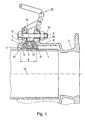
- Fig. 1 shows the section with a spigot 1, a sleeve 2, a clamping ring 4 consisting of links 3, a sealing ring 11, a sleeve ring 6 and a clamping ring 5, a screw member 19 and a clamping element 20.
- the insertion is through the clamping ring 5 in the sleeve 2 introduced.
- the sleeve has a sleeve ring 6 with a sleeve cone surface 8.
- This conical surface is inclined in the direction of the central axis 10. It should be noted that the term conical surface is not related to an exact conical surface, but to a conical shape. Accordingly, this surface is not necessarily straight on average, but may also be arched or curved.
- the clamping ring consists of a plurality of nested members 3, wherein in this section two members can be seen.
- the members each have a plug portion 14 and a receiving portion 15.
- a grip element 21 is further provided on the pipe side 12.
- This gripping element is formed in this embodiment L-shaped and has on the tube side prongs.
- Material of a gripping element offer those materials that are harder than the material of the insertion end to ensure that the teeth can dig into the surface of the insertion.
- the gripping elements are not designed as a continuous ring in this embodiment, but provided individually in each member. However, it is quite conceivable that the gripping elements extend over a plurality of links of the clamping ring, are designed as a flexible or slotted ring, or that the gripping elements consist of the same material as the links and / or that the links themselves have serrations on the tube side, which act as grip elements. For example, when using a slotted, or C-shaped ring, the spring-loaded ring could force the individual members approximately radially outwardly, thus maximizing the diameter of the ring upon insertion of the male end.
- tensioning element is designed in this embodiment as a multi-stage toggle lever quick-clamping system.
- quick-release devices allow rapid clamping of the two rings (5, 6) against each other.
- Such devices may be, for example, buckles, ratchets, straps, cables, clips or the like. It is further noted that these quick release devices can also replace the screw connection.
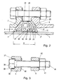
- Fig. 2 shows a detailed representation of another embodiment of the clamping ring 4 according to the invention, which is pressed against the insertion end 1 of a tube, wherein the forces in the tube direction through the conical surfaces: clamping cone surface 7 and sleeve taper surface 8 are generated.
- the clamping ring has a width 9, which decreases with increasing distance from the tube central axis 10.
- the oblique side walls of the side cheeks 16 are tapered and thereby represented in this section as a straight line.
- the angles of the side walls to the insertion of the tube may be different on the sleeve side and on the clamping ring side, but also the same.
- the angle ⁇ of the clamping ring side is smaller than the angle ⁇ of the sleeve side. This has the effect that the pull-out forces and thus the forces of the clamping ring and the clamping cone surface on the side cheeks 16 of the clamping ring are converted into radial forces, ie forces direction center pipe axis.
- the angle ⁇ is greater in order to reduce the elongation and shear of the seal.
- a sealing groove 27 is provided, in which the holding extension 28 of the sealing ring 11 can be inserted.
- the sealing ring also has one or more tube beads which, similar to O-rings, improve the sealing effect.
- a sleeve bead 23 is provided to improve the sealing effect.
- the clamping cone surface and the clamping ring touch each other in this embodiment along a circular line.
- This line contact is given by the different cone angles. Even with curved, conical surfaces, there is a line contact. Depending on the load and requirement, however, it may also be advisable to provide a surface contact of the two surfaces.
- the sleeve cone surface and the clamping ring, in particular the sealing ring and the socket cone surface have no surface contact in this embodiment. Only when crushing the elastic seal, it comes to a surface contact. Also at this point it is quite conceivable, depending on the requirement, to provide a basic surface contact.
- a dirt seal lip 22 is provided on the outward side of the clamping ring 4. This covers the outwardly facing portion to prevent ingress of sand, soil or similar polluting objects in the clamping ring or in the columns of the clamping ring between the individual members.
- the sealing lip covered in this embodiment, the outside of the clamping ring can of course also be pulled on the clamping ring side on.
- Grip elements 21 are provided on the tube side of the clamping ring, in particular on the tube side of the plug-in sections of the links. These are L-shaped with this embodiment and have on their side tube grip 29. The attachment to the clamping ring takes place in this embodiment by clamping a holding extension 30 in a retaining groove 31 of the member.
- Fig. 3 shows a section through the screw which connects the clamping ring 5 with the sleeve ring 6 and / or makes these parts to each other drawable.
- a screw connection is provided.
- other types of connection such as ratchets, clamps, rivets, elastic features, tensioners, buckles and the like.
- the connecting element, here the screw member 19 serves the movement or tension of the clamping ring 5 against the sleeve ring 6. Since the operation of this screw member happens in practice in hard to reach areas, it is necessary to make this connection as easy to use as possible.
- the screw head 36 is designed as a hexagon and is located in a screw head opening 37, which side cheeks 38 has the screw head opening.
- This opening is designed such that the insertion of the screw and the screw head is indeed possible, a rotational movement of the inserted screw, but in particular the inserted screw head is hampered.
- a protective element 39 is provided to protect the notch effect of the screw head in the screw head opening 37 so that the said protective layer is not violated, even if the tightening torque of the screw is very large, to protect the, usually provided for pipe elements anti-corrosion coating.
- a holding element 40 is provided, which is clamped on the screw shaft and thus prevents falling out of the screw from the opening of the clamping ring.
- a nut 41 is provided, which passes on a washer 42, the longitudinal tension of the tightened screw on the sleeve ring.
- a washer 42 the longitudinal tension of the tightened screw on the sleeve ring.
- the washer can also be replaced by elements such as clamping rings, Schnorr discs, wedge discs, spring washers and the like.
- Fig. 4 shows a view of a member 3 from the side of the receiving portion 15 with two side cheeks 16 - a sleeve cheek 25 and a clamping ring cheek 26, a plug portion 14 and a receiving portion 15, wherein on the side cheeks, in this embodiment on the sleeve cheek 25, a sealing groove 27, and provided at the plug portion a retaining groove 31 for a grip element.
- recesses 18 are provided in the region of the receiving portion. These recesses are designed slot-shaped or oblong-curved. They serve as further in Fig. 5 the recording of the pin 17 is described.
- Apron elements 32 are provided in the outer regions of the side cheeks 16. These overlap with mated limbs, the side walls of the subsequent member at least partially.
- the aprons serve on the one hand the seal against contamination from the outside and on the other hand, by their curved shape of the centering and guiding the members to each other. Furthermore, they form, as well as parts of the male portion and the receiving portion as a stop.
- Fig. 5 shows the same member as Fig. 4 However, viewed from the Steckabitessseite. It has a plug-in section 14, a receiving section 15, side walls 16 with skirt elements 32. At the plug portion 14, pins 17 are provided on both sides. These pins extend in the lateral direction away from the plug portion and engage with mated elements in the also provided on both sides slot-like recesses 18 of the receiving portions 15 of the following members.
- a spring element 34 is provided on the end face 33 of the plug portion 14. This spring element is used for the resilient spacing to the next member.
- Fig. 6 shows a side view of a series of nested members 3, which form a segment of the clamping ring 4.
- Fig. 6a shows this section in the widest possible extended position
- Fig. 6b shows the same arrangement in the widest possible pushed together position.
- the links each have a plug-in section 14 and a receiving section 15.
- pins 17 are provided, which can engage in the recesses 18 of the plug-in sections.
- These recesses 18 have a shape so that the pins have a certain mobility, in particular a guide in this.
- these recesses are formed in the illustrated embodiment slot-shaped, wherein the longitudinal sides are curved.
- each apron element 32 of the side cheek 16 engages over the subsequent member, in particular the plug-in portion and at least a portion of the receiving portion.
- the plug connection namely the plug-in portion with the pins 17 provided thereon and the recesses 18 of the receiving portion is therefore protected in each extended position and thus not accessible from the outside. This has the advantage that soiling such as soil, sand, gravel, etc. has no way to penetrate into this area and affect the mobility of the clamping ring 4 so.
Landscapes
- Engineering & Computer Science (AREA)
- General Engineering & Computer Science (AREA)
- Mechanical Engineering (AREA)
- Quick-Acting Or Multi-Walled Pipe Joints (AREA)
- Joints With Sleeves (AREA)
- Flanged Joints, Insulating Joints, And Other Joints (AREA)
- Joints Allowing Movement (AREA)
- Clamps And Clips (AREA)
- Mutual Connection Of Rods And Tubes (AREA)
Priority Applications (1)
| Application Number | Priority Date | Filing Date | Title |
|---|---|---|---|
| PL11711783T PL2561260T3 (pl) | 2010-04-01 | 2011-03-29 | Urządzenie do łączenia rur |
Applications Claiming Priority (2)
| Application Number | Priority Date | Filing Date | Title |
|---|---|---|---|
| AT0052510A AT509694B1 (de) | 2010-04-01 | 2010-04-01 | Rohrverbindungsvorrichtung |
| PCT/EP2011/001558 WO2011120669A1 (de) | 2010-04-01 | 2011-03-29 | Rohrverbindungsvorrichtung |
Publications (2)
| Publication Number | Publication Date |
|---|---|
| EP2561260A1 EP2561260A1 (de) | 2013-02-27 |
| EP2561260B1 true EP2561260B1 (de) | 2014-12-03 |
Family
ID=44146963
Family Applications (1)
| Application Number | Title | Priority Date | Filing Date |
|---|---|---|---|
| EP11711783.8A Active EP2561260B1 (de) | 2010-04-01 | 2011-03-29 | Rohrverbindungsvorrichtung |
Country Status (10)
| Country | Link |
|---|---|
| EP (1) | EP2561260B1 (pl) |
| JP (1) | JP5753575B2 (pl) |
| KR (1) | KR101791234B1 (pl) |
| AT (1) | AT509694B1 (pl) |
| DK (1) | DK2561260T3 (pl) |
| ES (1) | ES2527244T3 (pl) |
| PL (1) | PL2561260T3 (pl) |
| PT (1) | PT2561260E (pl) |
| RU (1) | RU2538135C2 (pl) |
| WO (1) | WO2011120669A1 (pl) |
Families Citing this family (4)
| Publication number | Priority date | Publication date | Assignee | Title |
|---|---|---|---|---|
| CA2944828C (en) | 2014-05-22 | 2020-10-27 | Georg Fischer Waga N.V. | Fitting for coupling to a pipe |
| NL2012869B1 (en) * | 2014-05-22 | 2016-03-15 | Fischer Georg Waga Nv | Fitting for coupling to a pipe. |
| AT524049B1 (de) * | 2020-12-15 | 2022-02-15 | E Hawle Armaturenwerke Gmbh | Rohrverbindungsvorrichtung mit einem dichtungsträger |
| EP4538573A4 (en) * | 2022-06-06 | 2026-03-18 | Jinan Mech Valve Tech Co Ltd | PIPE CONNECTION SYSTEM |
Citations (1)
| Publication number | Priority date | Publication date | Assignee | Title |
|---|---|---|---|---|
| GB2377737B (en) * | 2001-07-18 | 2004-02-25 | Saint Gobain Pipelines Plc | Improvements in or relating to pipe couplings |
Family Cites Families (12)
| Publication number | Priority date | Publication date | Assignee | Title |
|---|---|---|---|---|
| US3189962A (en) * | 1962-11-07 | 1965-06-22 | Amp Inc | Clamping device |
| US4678211A (en) * | 1984-08-10 | 1987-07-07 | Stanton And Staveley Limited | Joints formed with welded flange pipes |
| GB8830202D0 (en) | 1988-12-23 | 1989-02-22 | Parkfield Group Plc | Pipe coupling |
| JPH048888U (pl) * | 1990-05-14 | 1992-01-27 | ||
| FR2683609B1 (fr) * | 1991-11-07 | 1995-01-20 | Pont A Mousson | Joint verrouille pour canalisations. |
| NL1002514C2 (nl) * | 1996-03-04 | 1997-09-05 | Fischer Georg Waga Nv | Koppelinrichting. |
| FR2762054B1 (fr) * | 1997-04-09 | 1999-05-21 | Pont A Mousson | Jonc fendu metallique pour joint verrouille entre elements de canalisation, et joint verrouille correspondant |
| JP3904697B2 (ja) * | 1997-10-27 | 2007-04-11 | コスモ工機株式会社 | 流体管の締付具 |
| GB2363437B (en) | 2000-06-13 | 2004-08-11 | Glynwed Pipe Systems Ltd | Method and apparatus for coupling pipe ends and a sealing and gripping assembly for the apparatus |
| JP2005042878A (ja) * | 2003-07-25 | 2005-02-17 | Daidore Kk | 管継手構造 |
| EP1906073A1 (en) * | 2006-09-26 | 2008-04-02 | Ludwig Frischhut GmbH & Co. KG | Sealing organ for a tube |
| PT103946B (pt) * | 2008-01-28 | 2009-05-04 | Fucoli Somepal Fundicao De Fer | Junta multimateriais com garras de bloqueio |
-
2010
- 2010-04-01 AT AT0052510A patent/AT509694B1/de active
-
2011
- 2011-03-29 EP EP11711783.8A patent/EP2561260B1/de active Active
- 2011-03-29 RU RU2012141177/06A patent/RU2538135C2/ru active
- 2011-03-29 WO PCT/EP2011/001558 patent/WO2011120669A1/de not_active Ceased
- 2011-03-29 PT PT117117838T patent/PT2561260E/pt unknown
- 2011-03-29 JP JP2013501679A patent/JP5753575B2/ja active Active
- 2011-03-29 ES ES11711783.8T patent/ES2527244T3/es active Active
- 2011-03-29 PL PL11711783T patent/PL2561260T3/pl unknown
- 2011-03-29 KR KR1020127028696A patent/KR101791234B1/ko not_active Expired - Fee Related
- 2011-03-29 DK DK11711783.8T patent/DK2561260T3/da active
Patent Citations (1)
| Publication number | Priority date | Publication date | Assignee | Title |
|---|---|---|---|---|
| GB2377737B (en) * | 2001-07-18 | 2004-02-25 | Saint Gobain Pipelines Plc | Improvements in or relating to pipe couplings |
Also Published As
| Publication number | Publication date |
|---|---|
| PL2561260T3 (pl) | 2015-05-29 |
| PT2561260E (pt) | 2015-02-04 |
| KR20130092949A (ko) | 2013-08-21 |
| AT509694B1 (de) | 2012-02-15 |
| RU2538135C2 (ru) | 2015-01-10 |
| ES2527244T3 (es) | 2015-01-21 |
| EP2561260A1 (de) | 2013-02-27 |
| AT509694A1 (de) | 2011-10-15 |
| DK2561260T3 (da) | 2015-02-16 |
| RU2012141177A (ru) | 2014-05-10 |
| JP5753575B2 (ja) | 2015-07-22 |
| WO2011120669A1 (de) | 2011-10-06 |
| KR101791234B1 (ko) | 2017-10-27 |
| JP2013524110A (ja) | 2013-06-17 |
Similar Documents
| Publication | Publication Date | Title |
|---|---|---|
| DE60133461T2 (de) | Rohrverbindungsvorrichtung | |
| DE3531540C2 (de) | Eine die Trennung verhindernde Rohrverbindung | |
| DE1475688A1 (de) | Klemmvorrichtung,insbesondere fuer Rohrleitungen | |
| WO2006018384A1 (de) | Steckverbindung für fluid-leitungen | |
| EP3377796B1 (de) | Kupplungselement für eine kupplung zur verbindung von druckmittelleitungen | |
| DE2162435A1 (de) | Schubsicherung von gummigedichteten rohrverbindungen | |
| EP3308066A1 (de) | Schelle mit schellenband und vorpositionierer | |
| DE102014205626A1 (de) | Dichtungsvorrichtung | |
| AT509694B1 (de) | Rohrverbindungsvorrichtung | |
| EP2317357B1 (de) | Kupplung für Lichtwellenleiterrohre | |
| DE2610878A1 (de) | Rohrverbindung mit einer schraubmuffe | |
| DE60114302T2 (de) | Rohrkupplung | |
| DE202011109164U1 (de) | Maul- oder klauenförmige Spaltdichtung | |
| EP2527694B1 (de) | Maul- oder klauenförmige Spaltdichtung | |
| DE4342854C2 (de) | Schubsicherung für eine Schraubmuffenverbindung für Rohrleitungen großer Nennweite | |
| DE2439100A1 (de) | Rohrverbindungsstueck mit verriegelungsmechanismus | |
| AT508261B1 (de) | Anschlussvorrichtung für ein kunststoffrohr | |
| DE1800923C3 (de) | Zug- und Schubsicherung für Schraubmuffen-Verbindungen von Rohren | |
| DE2638586C2 (de) | Schubsicherung für Muffenverbindungen | |
| EP1847744A2 (de) | Vorrichtung zum Abdichten eines Rohrs | |
| DE2715618A1 (de) | Rohrverbindungsstueck | |
| DE20214463U1 (de) | Symmetrische Schlauchkupplung | |
| EP1245888B1 (de) | Positionsadapter für Rohr- und Kabelverbindungen | |
| DE102025105847B4 (de) | Lastgreifer für einen Eingriff an einer Bohrung in der Last | |
| DE29901351U1 (de) | Verstellbarer Keilring |
Legal Events
| Date | Code | Title | Description |
|---|---|---|---|
| PUAI | Public reference made under article 153(3) epc to a published international application that has entered the european phase |
Free format text: ORIGINAL CODE: 0009012 |
|
| 17P | Request for examination filed |
Effective date: 20120918 |
|
| AK | Designated contracting states |
Kind code of ref document: A1 Designated state(s): AL AT BE BG CH CY CZ DE DK EE ES FI FR GB GR HR HU IE IS IT LI LT LU LV MC MK MT NL NO PL PT RO RS SE SI SK SM TR |
|
| TPAC | Observations filed by third parties |
Free format text: ORIGINAL CODE: EPIDOSNTIPA |
|
| DAX | Request for extension of the european patent (deleted) | ||
| 17Q | First examination report despatched |
Effective date: 20130830 |
|
| GRAP | Despatch of communication of intention to grant a patent |
Free format text: ORIGINAL CODE: EPIDOSNIGR1 |
|
| INTG | Intention to grant announced |
Effective date: 20140625 |
|
| GRAS | Grant fee paid |
Free format text: ORIGINAL CODE: EPIDOSNIGR3 |
|
| GRAA | (expected) grant |
Free format text: ORIGINAL CODE: 0009210 |
|
| AK | Designated contracting states |
Kind code of ref document: B1 Designated state(s): AL AT BE BG CH CY CZ DE DK EE ES FI FR GB GR HR HU IE IS IT LI LT LU LV MC MK MT NL NO PL PT RO RS SE SI SK SM TR |
|
| REG | Reference to a national code |
Ref country code: GB Ref legal event code: FG4D Free format text: NOT ENGLISH |
|
| REG | Reference to a national code |
Ref country code: AT Ref legal event code: REF Ref document number: 699570 Country of ref document: AT Kind code of ref document: T Effective date: 20141215 Ref country code: CH Ref legal event code: EP |
|
| REG | Reference to a national code |
Ref country code: IE Ref legal event code: FG4D Free format text: LANGUAGE OF EP DOCUMENT: GERMAN |
|
| REG | Reference to a national code |
Ref country code: DE Ref legal event code: R096 Ref document number: 502011005157 Country of ref document: DE Effective date: 20150115 Ref country code: CH Ref legal event code: NV Representative=s name: BOHEST AG, CH |
|
| REG | Reference to a national code |
Ref country code: ES Ref legal event code: FG2A Ref document number: 2527244 Country of ref document: ES Kind code of ref document: T3 Effective date: 20150121 |
|
| REG | Reference to a national code |
Ref country code: NL Ref legal event code: T3 |
|
| REG | Reference to a national code |
Ref country code: PT Ref legal event code: SC4A Free format text: AVAILABILITY OF NATIONAL TRANSLATION Effective date: 20150114 |
|
| REG | Reference to a national code |
Ref country code: DK Ref legal event code: T3 Effective date: 20150212 |
|
| PG25 | Lapsed in a contracting state [announced via postgrant information from national office to epo] |
Ref country code: FI Free format text: LAPSE BECAUSE OF FAILURE TO SUBMIT A TRANSLATION OF THE DESCRIPTION OR TO PAY THE FEE WITHIN THE PRESCRIBED TIME-LIMIT Effective date: 20141203 Ref country code: LT Free format text: LAPSE BECAUSE OF FAILURE TO SUBMIT A TRANSLATION OF THE DESCRIPTION OR TO PAY THE FEE WITHIN THE PRESCRIBED TIME-LIMIT Effective date: 20141203 |
|
| REG | Reference to a national code |
Ref country code: NO Ref legal event code: T2 Effective date: 20141203 |
|
| REG | Reference to a national code |
Ref country code: LT Ref legal event code: MG4D |
|
| PG25 | Lapsed in a contracting state [announced via postgrant information from national office to epo] |
Ref country code: CY Free format text: LAPSE BECAUSE OF FAILURE TO SUBMIT A TRANSLATION OF THE DESCRIPTION OR TO PAY THE FEE WITHIN THE PRESCRIBED TIME-LIMIT Effective date: 20141203 Ref country code: HR Free format text: LAPSE BECAUSE OF FAILURE TO SUBMIT A TRANSLATION OF THE DESCRIPTION OR TO PAY THE FEE WITHIN THE PRESCRIBED TIME-LIMIT Effective date: 20141203 Ref country code: GR Free format text: LAPSE BECAUSE OF FAILURE TO SUBMIT A TRANSLATION OF THE DESCRIPTION OR TO PAY THE FEE WITHIN THE PRESCRIBED TIME-LIMIT Effective date: 20150304 Ref country code: RS Free format text: LAPSE BECAUSE OF FAILURE TO SUBMIT A TRANSLATION OF THE DESCRIPTION OR TO PAY THE FEE WITHIN THE PRESCRIBED TIME-LIMIT Effective date: 20141203 Ref country code: SE Free format text: LAPSE BECAUSE OF FAILURE TO SUBMIT A TRANSLATION OF THE DESCRIPTION OR TO PAY THE FEE WITHIN THE PRESCRIBED TIME-LIMIT Effective date: 20141203 Ref country code: LV Free format text: LAPSE BECAUSE OF FAILURE TO SUBMIT A TRANSLATION OF THE DESCRIPTION OR TO PAY THE FEE WITHIN THE PRESCRIBED TIME-LIMIT Effective date: 20141203 |
|
| REG | Reference to a national code |
Ref country code: PL Ref legal event code: T3 |
|
| PG25 | Lapsed in a contracting state [announced via postgrant information from national office to epo] |
Ref country code: SK Free format text: LAPSE BECAUSE OF FAILURE TO SUBMIT A TRANSLATION OF THE DESCRIPTION OR TO PAY THE FEE WITHIN THE PRESCRIBED TIME-LIMIT Effective date: 20141203 Ref country code: RO Free format text: LAPSE BECAUSE OF FAILURE TO SUBMIT A TRANSLATION OF THE DESCRIPTION OR TO PAY THE FEE WITHIN THE PRESCRIBED TIME-LIMIT Effective date: 20141203 Ref country code: EE Free format text: LAPSE BECAUSE OF FAILURE TO SUBMIT A TRANSLATION OF THE DESCRIPTION OR TO PAY THE FEE WITHIN THE PRESCRIBED TIME-LIMIT Effective date: 20141203 |
|
| PG25 | Lapsed in a contracting state [announced via postgrant information from national office to epo] |
Ref country code: IS Free format text: LAPSE BECAUSE OF FAILURE TO SUBMIT A TRANSLATION OF THE DESCRIPTION OR TO PAY THE FEE WITHIN THE PRESCRIBED TIME-LIMIT Effective date: 20150403 |
|
| REG | Reference to a national code |
Ref country code: DE Ref legal event code: R097 Ref document number: 502011005157 Country of ref document: DE |
|
| PLBE | No opposition filed within time limit |
Free format text: ORIGINAL CODE: 0009261 |
|
| STAA | Information on the status of an ep patent application or granted ep patent |
Free format text: STATUS: NO OPPOSITION FILED WITHIN TIME LIMIT |
|
| PG25 | Lapsed in a contracting state [announced via postgrant information from national office to epo] |
Ref country code: MC Free format text: LAPSE BECAUSE OF FAILURE TO SUBMIT A TRANSLATION OF THE DESCRIPTION OR TO PAY THE FEE WITHIN THE PRESCRIBED TIME-LIMIT Effective date: 20141203 Ref country code: LU Free format text: LAPSE BECAUSE OF FAILURE TO SUBMIT A TRANSLATION OF THE DESCRIPTION OR TO PAY THE FEE WITHIN THE PRESCRIBED TIME-LIMIT Effective date: 20150329 |
|
| 26N | No opposition filed |
Effective date: 20150904 |
|
| PG25 | Lapsed in a contracting state [announced via postgrant information from national office to epo] |
Ref country code: IT Free format text: LAPSE BECAUSE OF FAILURE TO SUBMIT A TRANSLATION OF THE DESCRIPTION OR TO PAY THE FEE WITHIN THE PRESCRIBED TIME-LIMIT Effective date: 20141203 |
|
| REG | Reference to a national code |
Ref country code: FR Ref legal event code: ST Effective date: 20151130 |
|
| REG | Reference to a national code |
Ref country code: IE Ref legal event code: MM4A |
|
| PG25 | Lapsed in a contracting state [announced via postgrant information from national office to epo] |
Ref country code: IE Free format text: LAPSE BECAUSE OF NON-PAYMENT OF DUE FEES Effective date: 20150329 |
|
| PG25 | Lapsed in a contracting state [announced via postgrant information from national office to epo] |
Ref country code: SI Free format text: LAPSE BECAUSE OF FAILURE TO SUBMIT A TRANSLATION OF THE DESCRIPTION OR TO PAY THE FEE WITHIN THE PRESCRIBED TIME-LIMIT Effective date: 20141203 Ref country code: FR Free format text: LAPSE BECAUSE OF NON-PAYMENT OF DUE FEES Effective date: 20150331 |
|
| PG25 | Lapsed in a contracting state [announced via postgrant information from national office to epo] |
Ref country code: MT Free format text: LAPSE BECAUSE OF FAILURE TO SUBMIT A TRANSLATION OF THE DESCRIPTION OR TO PAY THE FEE WITHIN THE PRESCRIBED TIME-LIMIT Effective date: 20141203 |
|
| REG | Reference to a national code |
Ref country code: AT Ref legal event code: MM01 Ref document number: 699570 Country of ref document: AT Kind code of ref document: T Effective date: 20160329 |
|
| PG25 | Lapsed in a contracting state [announced via postgrant information from national office to epo] |
Ref country code: SM Free format text: LAPSE BECAUSE OF FAILURE TO SUBMIT A TRANSLATION OF THE DESCRIPTION OR TO PAY THE FEE WITHIN THE PRESCRIBED TIME-LIMIT Effective date: 20141203 Ref country code: HU Free format text: LAPSE BECAUSE OF FAILURE TO SUBMIT A TRANSLATION OF THE DESCRIPTION OR TO PAY THE FEE WITHIN THE PRESCRIBED TIME-LIMIT; INVALID AB INITIO Effective date: 20110329 Ref country code: BG Free format text: LAPSE BECAUSE OF FAILURE TO SUBMIT A TRANSLATION OF THE DESCRIPTION OR TO PAY THE FEE WITHIN THE PRESCRIBED TIME-LIMIT Effective date: 20141203 |
|
| PG25 | Lapsed in a contracting state [announced via postgrant information from national office to epo] |
Ref country code: TR Free format text: LAPSE BECAUSE OF FAILURE TO SUBMIT A TRANSLATION OF THE DESCRIPTION OR TO PAY THE FEE WITHIN THE PRESCRIBED TIME-LIMIT Effective date: 20141203 Ref country code: AT Free format text: LAPSE BECAUSE OF NON-PAYMENT OF DUE FEES Effective date: 20160329 |
|
| PG25 | Lapsed in a contracting state [announced via postgrant information from national office to epo] |
Ref country code: MK Free format text: LAPSE BECAUSE OF FAILURE TO SUBMIT A TRANSLATION OF THE DESCRIPTION OR TO PAY THE FEE WITHIN THE PRESCRIBED TIME-LIMIT Effective date: 20141203 |
|
| PG25 | Lapsed in a contracting state [announced via postgrant information from national office to epo] |
Ref country code: AL Free format text: LAPSE BECAUSE OF FAILURE TO SUBMIT A TRANSLATION OF THE DESCRIPTION OR TO PAY THE FEE WITHIN THE PRESCRIBED TIME-LIMIT Effective date: 20141203 |
|
| PGFP | Annual fee paid to national office [announced via postgrant information from national office to epo] |
Ref country code: ES Payment date: 20250428 Year of fee payment: 15 |
|
| PGFP | Annual fee paid to national office [announced via postgrant information from national office to epo] |
Ref country code: CH Payment date: 20250401 Year of fee payment: 15 |
|
| REG | Reference to a national code |
Ref country code: CH Ref legal event code: U11 Free format text: ST27 STATUS EVENT CODE: U-0-0-U10-U11 (AS PROVIDED BY THE NATIONAL OFFICE) Effective date: 20260401 |
|
| PGFP | Annual fee paid to national office [announced via postgrant information from national office to epo] |
Ref country code: GB Payment date: 20260324 Year of fee payment: 16 |
|
| PGFP | Annual fee paid to national office [announced via postgrant information from national office to epo] |
Ref country code: NO Payment date: 20260323 Year of fee payment: 16 Ref country code: DE Payment date: 20260304 Year of fee payment: 16 Ref country code: DK Payment date: 20260324 Year of fee payment: 16 |
|
| PGFP | Annual fee paid to national office [announced via postgrant information from national office to epo] |
Ref country code: BE Payment date: 20260319 Year of fee payment: 16 |
|
| PGFP | Annual fee paid to national office [announced via postgrant information from national office to epo] |
Ref country code: NL Payment date: 20260319 Year of fee payment: 16 |
|
| PGFP | Annual fee paid to national office [announced via postgrant information from national office to epo] |
Ref country code: CZ Payment date: 20260324 Year of fee payment: 16 Ref country code: PT Payment date: 20260319 Year of fee payment: 16 |
|
| PGFP | Annual fee paid to national office [announced via postgrant information from national office to epo] |
Ref country code: PL Payment date: 20260105 Year of fee payment: 16 |