EP2561973A1 - Dispositif et procédé de fabrication de corps tubulaires - Google Patents
Dispositif et procédé de fabrication de corps tubulaires Download PDFInfo
- Publication number
- EP2561973A1 EP2561973A1 EP11178397A EP11178397A EP2561973A1 EP 2561973 A1 EP2561973 A1 EP 2561973A1 EP 11178397 A EP11178397 A EP 11178397A EP 11178397 A EP11178397 A EP 11178397A EP 2561973 A1 EP2561973 A1 EP 2561973A1
- Authority
- EP
- European Patent Office
- Prior art keywords
- substrate
- conveying direction
- welding
- tube
- web
- Prior art date
- Legal status (The legal status is an assumption and is not a legal conclusion. Google has not performed a legal analysis and makes no representation as to the accuracy of the status listed.)
- Withdrawn
Links
- 238000004519 manufacturing process Methods 0.000 title claims abstract description 14
- 238000000034 method Methods 0.000 title claims abstract description 13
- 239000000758 substrate Substances 0.000 claims abstract description 106
- 238000003466 welding Methods 0.000 claims description 65
- 230000002093 peripheral effect Effects 0.000 claims description 4
- 238000011144 upstream manufacturing Methods 0.000 abstract description 4
- 238000007493 shaping process Methods 0.000 abstract description 3
- 238000005259 measurement Methods 0.000 abstract description 2
- 239000003795 chemical substances by application Substances 0.000 description 7
- 230000003993 interaction Effects 0.000 description 5
- 238000001514 detection method Methods 0.000 description 3
- 238000011161 development Methods 0.000 description 3
- 230000018109 developmental process Effects 0.000 description 3
- 238000000465 moulding Methods 0.000 description 3
- 238000005520 cutting process Methods 0.000 description 2
- 230000002950 deficient Effects 0.000 description 2
- 238000012935 Averaging Methods 0.000 description 1
- 230000003044 adaptive effect Effects 0.000 description 1
- 239000011230 binding agent Substances 0.000 description 1
- 238000007664 blowing Methods 0.000 description 1
- 238000004364 calculation method Methods 0.000 description 1
- 238000010276 construction Methods 0.000 description 1
- 238000001816 cooling Methods 0.000 description 1
- 238000012937 correction Methods 0.000 description 1
- 230000007547 defect Effects 0.000 description 1
- 230000001419 dependent effect Effects 0.000 description 1
- 238000013461 design Methods 0.000 description 1
- 230000000694 effects Effects 0.000 description 1
- 238000001914 filtration Methods 0.000 description 1
- 238000012544 monitoring process Methods 0.000 description 1
- 230000003287 optical effect Effects 0.000 description 1
- 238000002407 reforming Methods 0.000 description 1
- 238000000926 separation method Methods 0.000 description 1
- 238000012549 training Methods 0.000 description 1
- 239000002699 waste material Substances 0.000 description 1
Images


Classifications
-
- B—PERFORMING OPERATIONS; TRANSPORTING
- B29—WORKING OF PLASTICS; WORKING OF SUBSTANCES IN A PLASTIC STATE IN GENERAL
- B29C—SHAPING OR JOINING OF PLASTICS; SHAPING OF MATERIAL IN A PLASTIC STATE, NOT OTHERWISE PROVIDED FOR; AFTER-TREATMENT OF THE SHAPED PRODUCTS, e.g. REPAIRING
- B29C65/00—Joining or sealing of preformed parts, e.g. welding of plastics materials; Apparatus therefor
- B29C65/78—Means for handling the parts to be joined, e.g. for making containers or hollow articles, e.g. means for handling sheets, plates, web-like materials, tubular articles, hollow articles or elements to be joined therewith; Means for discharging the joined articles from the joining apparatus
- B29C65/7802—Positioning the parts to be joined, e.g. aligning, indexing or centring
- B29C65/7832—Positioning the parts to be joined, e.g. aligning, indexing or centring by setting the overlap between the parts to be joined, e.g. the overlap between sheets, plates or web-like materials
-
- B—PERFORMING OPERATIONS; TRANSPORTING
- B32—LAYERED PRODUCTS
- B32B—LAYERED PRODUCTS, i.e. PRODUCTS BUILT-UP OF STRATA OF FLAT OR NON-FLAT, e.g. CELLULAR OR HONEYCOMB, FORM
- B32B41/00—Arrangements for controlling or monitoring lamination processes; Safety arrangements
-
- B—PERFORMING OPERATIONS; TRANSPORTING
- B29—WORKING OF PLASTICS; WORKING OF SUBSTANCES IN A PLASTIC STATE IN GENERAL
- B29C—SHAPING OR JOINING OF PLASTICS; SHAPING OF MATERIAL IN A PLASTIC STATE, NOT OTHERWISE PROVIDED FOR; AFTER-TREATMENT OF THE SHAPED PRODUCTS, e.g. REPAIRING
- B29C53/00—Shaping by bending, folding, twisting, straightening or flattening; Apparatus therefor
- B29C53/36—Bending and joining, e.g. for making hollow articles
- B29C53/38—Bending and joining, e.g. for making hollow articles by bending sheets or strips at right angles to the longitudinal axis of the article being formed and joining the edges
- B29C53/48—Bending and joining, e.g. for making hollow articles by bending sheets or strips at right angles to the longitudinal axis of the article being formed and joining the edges for articles of indefinite length, i.e. bending a strip progressively
- B29C53/54—Guiding, aligning or shaping edges
-
- B—PERFORMING OPERATIONS; TRANSPORTING
- B29—WORKING OF PLASTICS; WORKING OF SUBSTANCES IN A PLASTIC STATE IN GENERAL
- B29C—SHAPING OR JOINING OF PLASTICS; SHAPING OF MATERIAL IN A PLASTIC STATE, NOT OTHERWISE PROVIDED FOR; AFTER-TREATMENT OF THE SHAPED PRODUCTS, e.g. REPAIRING
- B29C65/00—Joining or sealing of preformed parts, e.g. welding of plastics materials; Apparatus therefor
- B29C65/02—Joining or sealing of preformed parts, e.g. welding of plastics materials; Apparatus therefor by heating, with or without pressure
-
- B—PERFORMING OPERATIONS; TRANSPORTING
- B29—WORKING OF PLASTICS; WORKING OF SUBSTANCES IN A PLASTIC STATE IN GENERAL
- B29C—SHAPING OR JOINING OF PLASTICS; SHAPING OF MATERIAL IN A PLASTIC STATE, NOT OTHERWISE PROVIDED FOR; AFTER-TREATMENT OF THE SHAPED PRODUCTS, e.g. REPAIRING
- B29C65/00—Joining or sealing of preformed parts, e.g. welding of plastics materials; Apparatus therefor
- B29C65/78—Means for handling the parts to be joined, e.g. for making containers or hollow articles, e.g. means for handling sheets, plates, web-like materials, tubular articles, hollow articles or elements to be joined therewith; Means for discharging the joined articles from the joining apparatus
- B29C65/7858—Means for handling the parts to be joined, e.g. for making containers or hollow articles, e.g. means for handling sheets, plates, web-like materials, tubular articles, hollow articles or elements to be joined therewith; Means for discharging the joined articles from the joining apparatus characterised by the feeding movement of the parts to be joined
- B29C65/7888—Means for handling of moving sheets or webs
- B29C65/7894—Means for handling of moving sheets or webs of continuously moving sheets or webs
-
- B—PERFORMING OPERATIONS; TRANSPORTING
- B29—WORKING OF PLASTICS; WORKING OF SUBSTANCES IN A PLASTIC STATE IN GENERAL
- B29C—SHAPING OR JOINING OF PLASTICS; SHAPING OF MATERIAL IN A PLASTIC STATE, NOT OTHERWISE PROVIDED FOR; AFTER-TREATMENT OF THE SHAPED PRODUCTS, e.g. REPAIRING
- B29C66/00—General aspects of processes or apparatus for joining preformed parts
- B29C66/01—General aspects dealing with the joint area or with the area to be joined
- B29C66/05—Particular design of joint configurations
- B29C66/10—Particular design of joint configurations particular design of the joint cross-sections
- B29C66/11—Joint cross-sections comprising a single joint-segment, i.e. one of the parts to be joined comprising a single joint-segment in the joint cross-section
- B29C66/112—Single lapped joints
- B29C66/1122—Single lap to lap joints, i.e. overlap joints
-
- B—PERFORMING OPERATIONS; TRANSPORTING
- B29—WORKING OF PLASTICS; WORKING OF SUBSTANCES IN A PLASTIC STATE IN GENERAL
- B29C—SHAPING OR JOINING OF PLASTICS; SHAPING OF MATERIAL IN A PLASTIC STATE, NOT OTHERWISE PROVIDED FOR; AFTER-TREATMENT OF THE SHAPED PRODUCTS, e.g. REPAIRING
- B29C66/00—General aspects of processes or apparatus for joining preformed parts
- B29C66/40—General aspects of joining substantially flat articles, e.g. plates, sheets or web-like materials; Making flat seams in tubular or hollow articles; Joining single elements to substantially flat surfaces
- B29C66/41—Joining substantially flat articles ; Making flat seams in tubular or hollow articles
- B29C66/43—Joining a relatively small portion of the surface of said articles
- B29C66/432—Joining a relatively small portion of the surface of said articles for making tubular articles or closed loops, e.g. by joining several sheets ; for making hollow articles or hollow preforms
- B29C66/4322—Joining a relatively small portion of the surface of said articles for making tubular articles or closed loops, e.g. by joining several sheets ; for making hollow articles or hollow preforms by joining a single sheet to itself
-
- B—PERFORMING OPERATIONS; TRANSPORTING
- B29—WORKING OF PLASTICS; WORKING OF SUBSTANCES IN A PLASTIC STATE IN GENERAL
- B29C—SHAPING OR JOINING OF PLASTICS; SHAPING OF MATERIAL IN A PLASTIC STATE, NOT OTHERWISE PROVIDED FOR; AFTER-TREATMENT OF THE SHAPED PRODUCTS, e.g. REPAIRING
- B29C66/00—General aspects of processes or apparatus for joining preformed parts
- B29C66/40—General aspects of joining substantially flat articles, e.g. plates, sheets or web-like materials; Making flat seams in tubular or hollow articles; Joining single elements to substantially flat surfaces
- B29C66/49—Internally supporting the, e.g. tubular, article during joining
-
- B—PERFORMING OPERATIONS; TRANSPORTING
- B29—WORKING OF PLASTICS; WORKING OF SUBSTANCES IN A PLASTIC STATE IN GENERAL
- B29C—SHAPING OR JOINING OF PLASTICS; SHAPING OF MATERIAL IN A PLASTIC STATE, NOT OTHERWISE PROVIDED FOR; AFTER-TREATMENT OF THE SHAPED PRODUCTS, e.g. REPAIRING
- B29C66/00—General aspects of processes or apparatus for joining preformed parts
- B29C66/80—General aspects of machine operations or constructions and parts thereof
- B29C66/83—General aspects of machine operations or constructions and parts thereof characterised by the movement of the joining or pressing tools
- B29C66/836—Moving relative to and tangentially to the parts to be joined, e.g. transversely to the displacement of the parts to be joined, e.g. using a X-Y table
-
- B—PERFORMING OPERATIONS; TRANSPORTING
- B29—WORKING OF PLASTICS; WORKING OF SUBSTANCES IN A PLASTIC STATE IN GENERAL
- B29C—SHAPING OR JOINING OF PLASTICS; SHAPING OF MATERIAL IN A PLASTIC STATE, NOT OTHERWISE PROVIDED FOR; AFTER-TREATMENT OF THE SHAPED PRODUCTS, e.g. REPAIRING
- B29C65/00—Joining or sealing of preformed parts, e.g. welding of plastics materials; Apparatus therefor
- B29C65/02—Joining or sealing of preformed parts, e.g. welding of plastics materials; Apparatus therefor by heating, with or without pressure
- B29C65/04—Dielectric heating, e.g. high-frequency welding, i.e. radio frequency welding of plastic materials having dielectric properties, e.g. PVC
-
- B—PERFORMING OPERATIONS; TRANSPORTING
- B29—WORKING OF PLASTICS; WORKING OF SUBSTANCES IN A PLASTIC STATE IN GENERAL
- B29C—SHAPING OR JOINING OF PLASTICS; SHAPING OF MATERIAL IN A PLASTIC STATE, NOT OTHERWISE PROVIDED FOR; AFTER-TREATMENT OF THE SHAPED PRODUCTS, e.g. REPAIRING
- B29C66/00—General aspects of processes or apparatus for joining preformed parts
- B29C66/70—General aspects of processes or apparatus for joining preformed parts characterised by the composition, physical properties or the structure of the material of the parts to be joined; Joining with non-plastics material
- B29C66/71—General aspects of processes or apparatus for joining preformed parts characterised by the composition, physical properties or the structure of the material of the parts to be joined; Joining with non-plastics material characterised by the composition of the plastics material of the parts to be joined
-
- B—PERFORMING OPERATIONS; TRANSPORTING
- B29—WORKING OF PLASTICS; WORKING OF SUBSTANCES IN A PLASTIC STATE IN GENERAL
- B29C—SHAPING OR JOINING OF PLASTICS; SHAPING OF MATERIAL IN A PLASTIC STATE, NOT OTHERWISE PROVIDED FOR; AFTER-TREATMENT OF THE SHAPED PRODUCTS, e.g. REPAIRING
- B29C66/00—General aspects of processes or apparatus for joining preformed parts
- B29C66/70—General aspects of processes or apparatus for joining preformed parts characterised by the composition, physical properties or the structure of the material of the parts to be joined; Joining with non-plastics material
- B29C66/72—General aspects of processes or apparatus for joining preformed parts characterised by the composition, physical properties or the structure of the material of the parts to be joined; Joining with non-plastics material characterised by the structure of the material of the parts to be joined
- B29C66/723—General aspects of processes or apparatus for joining preformed parts characterised by the composition, physical properties or the structure of the material of the parts to be joined; Joining with non-plastics material characterised by the structure of the material of the parts to be joined being multi-layered
- B29C66/7232—General aspects of processes or apparatus for joining preformed parts characterised by the composition, physical properties or the structure of the material of the parts to be joined; Joining with non-plastics material characterised by the structure of the material of the parts to be joined being multi-layered comprising a non-plastics layer
- B29C66/72321—General aspects of processes or apparatus for joining preformed parts characterised by the composition, physical properties or the structure of the material of the parts to be joined; Joining with non-plastics material characterised by the structure of the material of the parts to be joined being multi-layered comprising a non-plastics layer consisting of metals or their alloys
-
- B—PERFORMING OPERATIONS; TRANSPORTING
- B29—WORKING OF PLASTICS; WORKING OF SUBSTANCES IN A PLASTIC STATE IN GENERAL
- B29C—SHAPING OR JOINING OF PLASTICS; SHAPING OF MATERIAL IN A PLASTIC STATE, NOT OTHERWISE PROVIDED FOR; AFTER-TREATMENT OF THE SHAPED PRODUCTS, e.g. REPAIRING
- B29C66/00—General aspects of processes or apparatus for joining preformed parts
- B29C66/70—General aspects of processes or apparatus for joining preformed parts characterised by the composition, physical properties or the structure of the material of the parts to be joined; Joining with non-plastics material
- B29C66/72—General aspects of processes or apparatus for joining preformed parts characterised by the composition, physical properties or the structure of the material of the parts to be joined; Joining with non-plastics material characterised by the structure of the material of the parts to be joined
- B29C66/723—General aspects of processes or apparatus for joining preformed parts characterised by the composition, physical properties or the structure of the material of the parts to be joined; Joining with non-plastics material characterised by the structure of the material of the parts to be joined being multi-layered
- B29C66/7234—General aspects of processes or apparatus for joining preformed parts characterised by the composition, physical properties or the structure of the material of the parts to be joined; Joining with non-plastics material characterised by the structure of the material of the parts to be joined being multi-layered comprising a barrier layer
- B29C66/72341—General aspects of processes or apparatus for joining preformed parts characterised by the composition, physical properties or the structure of the material of the parts to be joined; Joining with non-plastics material characterised by the structure of the material of the parts to be joined being multi-layered comprising a barrier layer for gases
-
- B—PERFORMING OPERATIONS; TRANSPORTING
- B32—LAYERED PRODUCTS
- B32B—LAYERED PRODUCTS, i.e. PRODUCTS BUILT-UP OF STRATA OF FLAT OR NON-FLAT, e.g. CELLULAR OR HONEYCOMB, FORM
- B32B41/00—Arrangements for controlling or monitoring lamination processes; Safety arrangements
- B32B2041/04—Detecting wrong registration, misalignment, deviation, failure
-
- B—PERFORMING OPERATIONS; TRANSPORTING
- B32—LAYERED PRODUCTS
- B32B—LAYERED PRODUCTS, i.e. PRODUCTS BUILT-UP OF STRATA OF FLAT OR NON-FLAT, e.g. CELLULAR OR HONEYCOMB, FORM
- B32B2309/00—Parameters for the laminating or treatment process; Apparatus details
- B32B2309/70—Automated, e.g. using a computer or microcomputer
- B32B2309/72—For measuring or regulating, e.g. systems with feedback loops
Definitions
- the invention relates to an apparatus and a method for producing circumferentially closed tubular tube bodies according to the preambles of the independent claims.
- a web-shaped substrate is conveyed by conveying means, for example rollers and / or rollers in a conveying direction and formed by tube forming means, for example by rollers, rollers and / or stationary baffles, to form a tubular around a cylindrical mandrel.
- conveying means for example rollers and / or rollers in a conveying direction
- tube forming means for example by rollers, rollers and / or stationary baffles
- the two edge regions each of which adjoins one of the longitudinal edges of the substrate web, contact the tubular form in a contact region, for example in the form of an overlapping region, in which the two edge regions overlap or a contact position, for example in the form of a joint edge, in which the both longitudinal edges of the substrate are adjacent to each other (where the terms "contact area” and "contact position" are to be synonymous and interchangeable hereinafter).
- a contact region for example, by means of a high frequency welding device, the two edge regions are welded together to form a weld.
- the contact region can shift away from the welding position defined by the welding device, which often results in defective tube bodies. If the contact area runs alongside or only partially through the welding area, this can result in a lack of tightness and / or pressure resistance of the tube body.
- a wandering of the contact region in the circumferential direction occurs, for example, when the substrate web is replaced, when substrates are rolled up inhomogeneously, or when the tensile stress of the substrate web fluctuates.
- systems which try to keep the position of the substrate web transversely to the conveying direction before the forming process in the tubular shape, ie before the forming area, constant.
- ultrasonic sensors are used, which detect at least one longitudinal edge of the substrate web, and adjusting means, for example in the form of a pivotable roller, which can optionally correct a deviation of the edge position of the target position.
- this type of monitoring takes into account selectively the edge position of the substrate web at the detection point, but not the orientation of the substrate web so the angle at which the substrate web passes the edge sensor, which is why despite maintaining a desired edge position, the position of the contact area at the welding means may differ significantly from the welding position , Also, those influences that occur between the position of the edge sensor and the welding position are not taken into account. Such influences include, for example, fluctuation in the web tension and trajectory due to the friction between the mandrel and the substrate, or slippage of the substrate, or positional fluctuation of a reforming agent such as a binder. a form band. Thus, despite the control and correction of the web position to a desired position, deviation from contact area to welding position may occur.
- the present invention seeks to improve an apparatus and a method for producing circumferentially closed tubular tube bodies according to the preambles of the independent claims so that the quality of the tubes produced is maximized and at the same time the effort for the smooth Operation is minimized.
- first sensor means for example an ultrasonic edge sensor and / or optical image acquisition means, in the forming area, preferably at the level of the tube forming means (ie in the conveying direction section, over which the immediate interaction or contact area of the tube forming means with the substrate extends) or in a region upstream of this in the conveying direction (conveying direction section), and / or are provided in the conveying direction after the forming area, which serve to detect a feature of the substrate.
- first sensor means for example an ultrasonic edge sensor and / or optical image acquisition means
- the forming region also comprises the region of the substrate in which the substrate is already directed by the forming belt in tube form, but has not yet come into contact with the forming belt.
- the first sensor means are evidently arranged in front of the forming area, since the substrate layer is allegedly easier to detect here due to the simple web shape and because, for a fast regulation, it appears to be compelling as close as possible to the setting means.
- the feature of the substrate is preferably the circumferential position of the contact region itself, the position of one of the longitudinal edges of the substrate and / or a marking on the substrate.
- the marking preferably extends endlessly in the conveying direction, so that deviations can be correspondingly detected and corrected at any time.
- the peripheral position of the contact region is suitable as a feature to be detected; in the case of known boundary conditions (in particular known substrate web width) it may also be conceivable to detect the circumferential position of an edge of the substrate at a defined location in the conveying direction, since the distance (in the conveying direction) to the welding means and geometry of the mandrel indirectly the circumferential position of the contact area can be determined at the welding means. Analogously, it is conceivable to detect a marking on the substrate, which has a defined distance from the longitudinal edges of the substrate.
- the tube forming agents (forming agents) are preferably in Delivery direction at least in sections (such as forming rollers and / or as a forming belt) upstream of the mandrel.
- first control means are provided which control the adjusting means in response to the sensor signal of the first sensor means so that the contact area is directed in the circumferential direction in the direction of the welding position or held in the welding position.
- the first control means can indirectly control the adjusting means, that is about second control means, wherein an output of the first control means enters as input to the second control means, for example realized in the form of a cascade control with two partial control sections (whose controller may be formed by the first and second control means ).
- the control means directly control the adjusting means, ie without further control means, in particular without a further (inner) control loop.
- the invention makes it possible to keep the contact area permanently in the welding position or to react to possible deviations faster, without manual intervention by an operating person. This reduces rejects due to "false welding" outside the contact area.
- the invention improves the quality of the weld and thus the quality of the tubes, in particular their capacity.
- the contact region can be designed, for example, as an overlapping region of the two longitudinal edge regions. It is also conceivable that the contact region is formed as a joint edge of the two longitudinal edges of the substrate, in which the two longitudinal edges at the same radial height (around the mandrel) come to rest side by side and are welded together by the welding means, which under the technical term “butt welding "is known.
- the first sensor means are close to the welding position in the conveying direction, in particular at a distance of less than 1 m, preferably at a distance of from about 20 cm to about 80 cm.
- the first sensor means are close to the welding position, for example in the conveying direction at the level of the mandrel, and preferably with radial distance from the mandrel, i. arranged laterally, in particular above, of the mandrel.
- the adjusting means are designed so that they are preferably still flat, i. web-shaped, substrate transversely to the conveying direction and / or adjust in the circumferential direction. This makes it possible to influence the inlet position in the shaping means and thus also the circumferential position of the contact area.
- the adjusting means comprise at least one roller which is pivotable in an angular range about a pivot axis, which is arranged perpendicular to the conveying direction (transport direction or surface extension) and / or at an angle to the conveying direction of the substrate.
- an electric, pneumatic or hydraulic actuator is preferably used for pivoting.
- the roller can move purely passively by the movement of the substrate (rotate) or be actively driven by a drive rotationally.
- second, preferably in the conveying direction before the forming area and preferably close (in particular with a distance in the conveying direction less than 20 cm) of the adjusting means arranged sensor means for detecting the position of the substrate web are provided.
- the second sensor means may, similar to the first sensor means, detect the position of the substrate web approximately by detecting at least one of the longitudinal edges and / or the detection of a preferably endlessly extending in the conveying direction feature, in particular a mark.
- the second sensor means comprise an ultrasonic sensor which detects the position of at least one longitudinal edge of the substrate.
- Ultrasonic sensors are suitable because of their low susceptibility to interference.
- the longitudinal edges of the substrate are particularly prominent areas that can be easily detected.
- second control means which hold the substrate web in front of the tube forming means transversely to the conveying direction in a given position by controlling the adjusting means in response to the measured values of the second sensor means so that they compensate for deviations from the desired position, if necessary.
- the second control means control further (second) actuating means which are upstream or downstream of the (first) actuating means.
- the first control means and the second control means act together on the adjusting means taking into account the measured values of both the first sensor means and the second sensor means, wherein the second control means may also be part of the first control means, i. to be identical with these, for example in the form of a micro-controiler, which outputs a suitable control signal to the actuating means on the basis of a, in particular algorithmic, linking the measured values of the first and second sensor means (such as a weighted averaging) to adjust the contact area in the circumferential direction to the welding circumferential position or keep on this.
- the first and / or the second control means may also be particularly advantageously designed as regulators of a control loop, for example as a PID controller or as an adaptive controller, with the first control means being designed as regulators of an outer control loop whose output variable (output signal ) is supplied as a reference variable (input signal or setpoint) designed as a controller of an inner control loop second adjusting means.
- the requirements for the strip position in the transverse direction can be advantageously influenced by the adjusting means both by the values detected by the first sensor means and by the values detected by the second sensor means, whereby the first control means effectively uses the first control means first sensor means measured values recorded the desired position of the substrate web is influenced and is maintained by the second control means based on the detected by the second sensor means, the observance of this target position.
- a bypass may be provided, so that the outer control loop (effectively) is the only control loop and the first control means directly control the actuating means, which can be achieved in specific cases, a faster response to divergence of welding peripheral position and contact area. Furthermore, a defect of the inner control loop can thus be compensated for in the short term.
- the second sensor means it has proven to be advantageous to design and arrange the second sensor means so that they can detect the width of the substrate web, for example by detecting both of the longitudinal edges of the substrate web. This makes it easier to use different widths of substrate webs.
- the width of the substrate web is an essential information for determining the position of the contact region (computationally). With the width information, it is sufficient to detect the position of one of the edges of the substrate web, since the position of the other edge is defined on the basis of the geometric frame conditions (together with the width information), so that the first sensor means must also comprise only one edge sensor.
- the tube forming means is followed by an elongated, preferably cylindrical mandrel downstream in the conveying direction of the substrate web, wherein the tube forming means preferably place the substrate around the mandrel.
- This is due to its geometric shapes and its robustness particularly well suited for use for mechanical forming of tube bodies.
- the tubular shape can be divided by cutting means into individual tube body.
- cutting means can separate and / or mark individual tube bodies and / or sections of the tube form from the production process.
- the tube bodies can be blown out of their path by blowing means or mechanically ejected by means of force which (presumably) do not meet the quality requirements.
- individual tube bodies for example colored, can be marked according to their quality.
- control means thus control the means for separating and / or marking as a function of the circumferential position of the contact area detected by the first sensor means.
- a substrate web is conveyed in a conveying direction and is formed in a forming area by tube forming means in tube form.
- the substrate is welded in a contact region between a first and a preferably parallel second longitudinal edge by means of welding means.
- the position of the substrate web transversely to the conveying direction is, for example, of
- Controlling agents influenced.
- the circumferential position of the contact area preferably above the mandrel, detected by first sensor means and control first control means in response to the sensor signal of the first Sensor means the adjusting means so that the detected by the first sensor means contact area is adjusted in the circumferential direction in the direction of the welding circumferential position (directed) or held in this.
- the web-shaped substrate is held by the adjusting means transversely to the conveying direction in a desired position, wherein in particular the desired position is adjusted in dependence of the measured values of the first sensor means.
- measured values of second sensor means are taken into account for maintaining the target position, whereby ultrasonic sensors which detect an edge of the substrate web have proven to be particularly advantageous.
- the separation takes place with a time delay for mangle detection, so that even those tube body can be singled, which were welded before the detected error, thereby filtering is possible.
- the Aussonderstoff can be formed for example by pressure nozzles that blow the tube body or pipe sections from a standard run, for example in collection container.
- the individual tube bodies or sections of the tube shape in particular when passing through the first sensor means, assigned a time stamp individually and / or in a specific frequency. If the welding conditions are detected as insufficient in a certain time range (because the contact area is detected outside a permissible range), then the elements (tube body or sections of the tube shape) can be separated from the rejection means by means of the time stamps. Thus, for example, a nozzle is activated at the times in which elements with a time stamp to be eliminated run past it, and the elements are thus deliberately blown out.
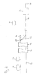
- Fig.1 shows in plan view a device according to a preferred embodiment of the invention.
- Fig. 2 shows the same device in a longitudinal view.
- the substrate web 10 is formed by tube forming means 12 in a tubular shape 13 about a cylindrical mandrel 14.
- the tube forming means 12 comprise concave guide rollers 16.
- a contact region 20 is formed between the longitudinal edges 18 and 19.
- Welding means 22, for example in the form of a high-frequency welding apparatus, and first sensor means 24 are arranged above the contact region 20.
- the first sensor means 24 are arranged here directly above the contact region formed as an overlap region, but alternatively it is also conceivable to arrange the first sensor means 24 shortly before the contact region, as in the position 24b shown in dashed lines.
- the first sensor means 24 one of the longitudinal edges detect the substrate and determine the position of this edge on the welding means based on the width of the substrate and the geometry of the molding means.
- a constant offset can be assumed, in which case the width of the substrate web 10 is preferably measured before reaching the tube forming means 12 for calculating this offset.
- the edge position can also be (analogous to the first longitudinal edge). be recorded.
- the substrate web 10 is adjusted by adjusting means 26 transversely to the conveying direction (web running direction or longitudinal direction of the substrate), i. moved parallel in the plane extension plane.
- second sensor means 27 are arranged here in the form of an ultrasonic edge sensor.
- the second sensor means 27 extend over the entire substrate web (as shown by dashed lines 27b), so that they can be the width of the substrate web detected and these as parameters for calculations (such as the computational determination of the circumferential position of the second longitudinal edge in the welding region with known Position of the first longitudinal edge) is available.
- control means which are signal-connected with each other and the adjusting means 26.
- This control means may be formed as a uniform control means or by logically separated first and second control means (such as a plurality of microcontroller).
- the substrate web is transported by in the drawing plane right to left and offset by means of the adjusting means 26 transversely to the conveying direction (shifted).
- An embodiment of the adjusting means 26 (as at least one rotatably mounted in a rotating frame roller) is in Fig. 3 and will be described later.
- the control means determines whether the web is offset by means of the adjusting means in the transverse direction (ie perpendicular to the conveying direction) so that they control the first adjusting means - more precisely an actuator of the adjusting roller - such that they adjust the substrate so that the longitudinal edge 18 is held in a desired position.
- the measurement results of the second sensor means 27 are taken into account by the control means in the control of the actuating means 26.
- a corresponding regulation is exemplified below in Fig. 5 shown and described.
- the web-shaped substrate 10 is made into a tubular shape by the tube-forming means 12.
- the substrate is bent by the guide rollers 16 and placed around the cylindrical mandrel 14, wherein the two edge regions contact the longitudinal edges 18 and 19 of the substrate, in particular overlap or abut each other, and in the circumferential direction between them the contact region 20, here in Shape of an overlap area.
- the welding means 22 the substrate is welded to itself in a welding area in such a way that a weld seam extending along the conveying direction of the pipe shape is formed, which in the ideal case coincides with the contact area.
- the welding means 22 are formed for example by welding bands, which are subjected to high frequency.
- the first sensor means 24 are arranged as close as possible to the welding means 22. They detect the position of the contact area 20 in the circumferential direction. Due to the short distance to the welding means 22, the position of the contact region 20 in the circumferential direction on the sensor means 24 corresponds as exactly as possible to the position of the contact region 20 in the circumferential direction on the welding means 22.
- the detected position of the contact region 20 is communicated to the control means via corresponding signal lines as a sensor signal. If the position of the contact region 20 is too far away from the center of the welding region (ie it comes too close to its edge) or is it outside the welding region, then the position of the substrate web 10 has to be adjusted so that the contact region 20 is closer to the center of the welding region Welding area is directed.
- the control means control the adjusting means accordingly, whereby the substrate web is offset in parallel, so that the contact area moves in the circumferential direction towards the welding area. If, for example, the contact area is to be displaced circumferentially in the clockwise direction (viewed in the conveyor or web direction), then the substrate web must be moved to the left in the conveying direction. Furthermore, it is conceivable by the course of the position of the contact region 20 to recognize a "run away" and counteract this early counter. An appropriate regulation is approximately in Fig. 5 described.
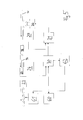
- Fig. 3 shows the adjusting means 26 in a preferred embodiment in a plan view.
- Figure 4 shows the same adjusting means 26 in a side view.
- the adjusting means 26 comprise an inlet roller 40, a rotating frame 42, two rotating frame rollers 43 and 44, and a fixing roller 46.
- the rollers are arranged in two pairs, each located at a height.
- a first pair form the inlet roller 40 and the fixing roller 46, a second pair of the two rotary frame rollers 43 and 44, which are mounted on the rotating frame 42.
- the rotary frame 42 is pivotable by a pivot angle 45 by means of a not shown for reasons of clarity, in particular electromotive actuator about a perpendicular to the conveying direction (on the rotating frame 42) standing pivot axis 48.
- the rotating frame 42 has a pivot frame length 47.
- the substrate web 10 enters the adjusting means 26 via the inlet roller 40. It is now guided via the rotating frame 42 with its rotary frame rollers 43 and 44 and finally leaves the setting means 26 via the fixing roller 46.
- offset Drehrahmenl ⁇ a ⁇ ⁇ nge * sin swivel angle
- the angle of rotation 45 must be increased.
- the present invention is not limited to the embodiment shown.
- the first sensor means 24 may also be arranged downstream of the welding means 22 in the conveying direction before the welding means 22, in addition to the position shown in the conveying direction.
- the invention provides in a particularly advantageous manner that the quality of the tubes produced is maximized while minimizing the effort for smooth operation.
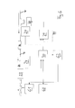
- Fig. 5 shows an exemplary circuit construction for controlling the adjusting means 26, wherein the control means are formed by first and second control means 30 and 31, respectively.
- a control loop (hereinafter referred to as “inner loop”) is provided, in which the second control means 31 are formed by a PID controller and in which the target position as a reference variable, the edge detected by the second sensor means 27 are regarded as a controlled variable.
- the second control means 31 give one of the control deviation (ie the difference between the desired position and the Edge position) dependent manipulated variable to the actuating means 26, so that the total edge position is guided to the desired position.
- an outer loop may be provided, in which the detected by the first sensor means 24 circumferential position of the contact portion 20 as a control variable and the circumferential position of the welding region of the welding means corresponding signal as a reference (Also) designed as a PID controller first control means 30 is supplied, which counteracts a deviation of the controlled variable of the reference variable by a corresponding manipulated variable to the inner control circuit (the second control means 31) outputs, which in turn received in this as a reference variable.
- a user interaction unit 60 can additionally serve to display any status information.
- Inner and / or outer control loop can also be implemented in software in a microcontroller, which processes the input signals of the two sensor means 24 and 27 accordingly digitally and outputs a suitable output signal to the actuating means 26.
- the position values detected by the two sensor means 24 and 27 can serve as input values of a function and / or an algorithm which from these input values an optimal position value of the longitudinal edge 18 of the substrate web 10 (by physically given conditions and / or by stored, previously determined records ) and output this as a corresponding electrical signal to the actuating means 26.
- discharge means 61 are provided which, if the control deviation is too great, activate the discharge and / or marking means 61 after a time delay (shown here by a delay unit 62), possibly weed out and / or mark defective tube bodies. Due to the time delay, the passage time of the substrate or the tube body from the first sensor means to the discharge means 61 is compensated.
- Fig. 6 extends the rule structure Figure 5 to the effect that the outer control loop can directly control the actuating means 26 by means of a bridging 70, that is, the control variable is received directly into the actuating means 26.
Landscapes
- Engineering & Computer Science (AREA)
- Mechanical Engineering (AREA)
- Lining Or Joining Of Plastics Or The Like (AREA)
- Shaping Of Tube Ends By Bending Or Straightening (AREA)
Priority Applications (6)
| Application Number | Priority Date | Filing Date | Title |
|---|---|---|---|
| EP11178397A EP2561973A1 (fr) | 2011-08-23 | 2011-08-23 | Dispositif et procédé de fabrication de corps tubulaires |
| CN201280052041.4A CN103958160B (zh) | 2011-08-23 | 2012-08-22 | 用于制造管体的设备和方法 |
| EP12761555.7A EP2651621B1 (fr) | 2011-08-23 | 2012-08-22 | Dispositif et procédé de fabrication de corps tubulaires |
| US14/240,047 US9931826B2 (en) | 2011-08-23 | 2012-08-22 | Device and method for manufacturing tube bodies |
| PCT/EP2012/066361 WO2013026888A1 (fr) | 2011-08-23 | 2012-08-22 | Dispositif et procédé pour produire des corps de tubes |
| JP2014526494A JP5778345B2 (ja) | 2011-08-23 | 2012-08-22 | チューブ体を製造する装置および方法 |
Applications Claiming Priority (1)
| Application Number | Priority Date | Filing Date | Title |
|---|---|---|---|
| EP11178397A EP2561973A1 (fr) | 2011-08-23 | 2011-08-23 | Dispositif et procédé de fabrication de corps tubulaires |
Publications (1)
| Publication Number | Publication Date |
|---|---|
| EP2561973A1 true EP2561973A1 (fr) | 2013-02-27 |
Family
ID=46880671
Family Applications (2)
| Application Number | Title | Priority Date | Filing Date |
|---|---|---|---|
| EP11178397A Withdrawn EP2561973A1 (fr) | 2011-08-23 | 2011-08-23 | Dispositif et procédé de fabrication de corps tubulaires |
| EP12761555.7A Active EP2651621B1 (fr) | 2011-08-23 | 2012-08-22 | Dispositif et procédé de fabrication de corps tubulaires |
Family Applications After (1)
| Application Number | Title | Priority Date | Filing Date |
|---|---|---|---|
| EP12761555.7A Active EP2651621B1 (fr) | 2011-08-23 | 2012-08-22 | Dispositif et procédé de fabrication de corps tubulaires |
Country Status (5)
| Country | Link |
|---|---|
| US (1) | US9931826B2 (fr) |
| EP (2) | EP2561973A1 (fr) |
| JP (1) | JP5778345B2 (fr) |
| CN (1) | CN103958160B (fr) |
| WO (1) | WO2013026888A1 (fr) |
Families Citing this family (3)
| Publication number | Priority date | Publication date | Assignee | Title |
|---|---|---|---|---|
| CN108790101A (zh) * | 2018-08-08 | 2018-11-13 | 新疆登煌管业有限公司 | 一种口模和芯模间隙调节装置及方法 |
| DE102019119491B4 (de) * | 2019-07-18 | 2021-10-07 | Sikora Ag | Verfahren und Vorrichtung zum Vermessen eines rohrförmigen Strangs |
| FI4194184T3 (fi) * | 2021-12-07 | 2025-09-02 | Fischer G Rohrleitungssysteme Ag | Hitsin arvioiminen hitsausprosessin aikana |
Citations (5)
| Publication number | Priority date | Publication date | Assignee | Title |
|---|---|---|---|---|
| JPS59230727A (ja) * | 1983-06-14 | 1984-12-25 | Gunze Ltd | 筒状シ−ル装置 |
| JPH05250944A (ja) * | 1992-03-06 | 1993-09-28 | Showa Electric Wire & Cable Co Ltd | テープ成型処理装置 |
| WO2001060588A1 (fr) * | 2000-02-17 | 2001-08-23 | Cebal S.A. | Procede de fabrication de tubes par soudure au laser |
| WO2003024694A1 (fr) * | 2001-09-12 | 2003-03-27 | Aisapack Holding Sa | Procede de commande de la position des bords d'une bande de film |
| WO2006013171A1 (fr) * | 2004-07-29 | 2006-02-09 | Siemens Aktiengesellschaft | Machine d'emballage pour sachets tubulaires |
Family Cites Families (6)
| Publication number | Priority date | Publication date | Assignee | Title |
|---|---|---|---|---|
| US3468731A (en) * | 1966-07-01 | 1969-09-23 | Branson Instr | Method and apparatus for sonically sealing the end portion of thermoplastic tubular containers |
| JPS60178117U (ja) * | 1984-05-04 | 1985-11-26 | 株式会社フジクラ | 縦添形パイプ状成形体の接合部自動追尾装置 |
| JP2803386B2 (ja) * | 1991-04-16 | 1998-09-24 | 株式会社明電舎 | 電縫管溶接管理方法およびその装置 |
| JP3628381B2 (ja) * | 1995-06-14 | 2005-03-09 | 株式会社フジシールインターナショナル | 筒状フィルムの製造装置 |
| US6310417B1 (en) | 1999-12-30 | 2001-10-30 | Lockheed Martin Energy Research Corporation | Hybrid-secondary uncluttered induction machine |
| JP4917802B2 (ja) * | 2005-12-22 | 2012-04-18 | 日本テトラパック株式会社 | 包装容器製造装置及び包装容器製造方法 |
-
2011
- 2011-08-23 EP EP11178397A patent/EP2561973A1/fr not_active Withdrawn
-
2012
- 2012-08-22 WO PCT/EP2012/066361 patent/WO2013026888A1/fr not_active Ceased
- 2012-08-22 US US14/240,047 patent/US9931826B2/en active Active
- 2012-08-22 EP EP12761555.7A patent/EP2651621B1/fr active Active
- 2012-08-22 CN CN201280052041.4A patent/CN103958160B/zh active Active
- 2012-08-22 JP JP2014526494A patent/JP5778345B2/ja active Active
Patent Citations (5)
| Publication number | Priority date | Publication date | Assignee | Title |
|---|---|---|---|---|
| JPS59230727A (ja) * | 1983-06-14 | 1984-12-25 | Gunze Ltd | 筒状シ−ル装置 |
| JPH05250944A (ja) * | 1992-03-06 | 1993-09-28 | Showa Electric Wire & Cable Co Ltd | テープ成型処理装置 |
| WO2001060588A1 (fr) * | 2000-02-17 | 2001-08-23 | Cebal S.A. | Procede de fabrication de tubes par soudure au laser |
| WO2003024694A1 (fr) * | 2001-09-12 | 2003-03-27 | Aisapack Holding Sa | Procede de commande de la position des bords d'une bande de film |
| WO2006013171A1 (fr) * | 2004-07-29 | 2006-02-09 | Siemens Aktiengesellschaft | Machine d'emballage pour sachets tubulaires |
Also Published As
| Publication number | Publication date |
|---|---|
| EP2651621B1 (fr) | 2014-10-15 |
| CN103958160B (zh) | 2016-10-12 |
| EP2651621A1 (fr) | 2013-10-23 |
| US9931826B2 (en) | 2018-04-03 |
| JP5778345B2 (ja) | 2015-09-16 |
| US20140318682A1 (en) | 2014-10-30 |
| JP2014527488A (ja) | 2014-10-16 |
| WO2013026888A1 (fr) | 2013-02-28 |
| CN103958160A (zh) | 2014-07-30 |
Similar Documents
| Publication | Publication Date | Title |
|---|---|---|
| DE19641509C2 (de) | Verfahren zum Transport eines Gürtelaufbaustreifens zum Aufbau eines Gürtels für einen Fahrzeugluftreifen | |
| EP3880399B1 (fr) | Procédé pour la découpe d'un matériau d'électrode de batterie continu pour fabriquer des électrodes de batterie | |
| DE202013105825U1 (de) | Spleißvorrichtung zum Spleißen von Cordbandstreifen | |
| DE60017864T2 (de) | Proaktive prozesssteuerung nach einem störenden ereignis | |
| EP3381303B1 (fr) | Procédé de fabrication de boudins tubulaires à au moins deux couches de l'industrie de transformation du tabac et dispositif de fabrication de boudins tubulaires à au moins deux couches de l'industrie de transformation du tabac | |
| DE102006017882B4 (de) | Vorrichtung und Verfahren zum Aufbau eines Reifens | |
| EP2982453A1 (fr) | Réglage d'un profil de température ciblé sur une tête de bande et pied de bande devant la partie transversale d'une bande métallique | |
| EP2651621B1 (fr) | Dispositif et procédé de fabrication de corps tubulaires | |
| DE112007000641B4 (de) | Kontinuierliche Kaltwalzanlage | |
| EP3233416B1 (fr) | Procédé et dispositif de mesure pour surveiller l'extensibilité lors de la fabrication d'un film étirable dans un procédé de feuille mince moulée | |
| EP3055126B1 (fr) | Procédé de formation d'une gaine à partir d'une bande continue de matériau plat, dispositif de formation de gaines et système de fabrication de sachets | |
| DE102019215492B4 (de) | Blasfolienanlage und Verfahren zur Herstellung von Folienschläuchen oder Folienbahnen | |
| WO2018195674A1 (fr) | Procédé et dispositif pour le soudage à la molette de corps de contenants | |
| EP2716170B2 (fr) | Dispositif de transport de matériau en forme de bande ou de ruban | |
| WO2017161399A1 (fr) | Procédé de mesure de la distribution en masse | |
| EP2384379B1 (fr) | Procede et dispositif d'identification d'une dechirure d'une bande de materiau | |
| DE102018127672A1 (de) | Verfahren für eine Kontrolle eines Randabschnitts einer Folienbahn | |
| WO2005107973A1 (fr) | Procede de laminage d'un produit a laminer presentant une zone de transition | |
| EP2283942A1 (fr) | Procédé d'influence d'une position d'un matériau de laminage traversant un train de laminage à plusieurs équipements, dispositif de commande et/ou de réglage pour une chaîne de laminage et chaîne de laminage | |
| WO2021156425A1 (fr) | Procédé d'étalonnage de rouleaux verticaux d'une cage de laminoir vertical et ensemble d'étalonnage pour la mise en œuvre du procédé | |
| EP3877145B1 (fr) | Procédé et dispositif permettant de contrôler la fente de buse d'une buse de sortie d'une machine de production de feuilles plates | |
| EP3307448A1 (fr) | Procédé et dispositif servant à réguler un paramètre d'un produit à laminer | |
| EP4587355A1 (fr) | Dispositif de commande et procédé de fonctionnement d'une installation de traitement de bande pour travailler une bande, en particulier une bande métallique ou un matériau de laminage | |
| EP4313817A1 (fr) | Procédé et dispositif de commande pour le fonctionnement d'une installation de traitement de bande pour traiter une bande, en particulier une bande métallique ou un matériau de laminage | |
| DE102018127675A1 (de) | Verfahren für eine Kalibrierung von Stellmitteln zur Verstellung eines Düsenspaltes einer Austrittsdüse für eine Folienbahn an einer Flachfolienmaschine |
Legal Events
| Date | Code | Title | Description |
|---|---|---|---|
| PUAI | Public reference made under article 153(3) epc to a published international application that has entered the european phase |
Free format text: ORIGINAL CODE: 0009012 |
|
| AK | Designated contracting states |
Kind code of ref document: A1 Designated state(s): AL AT BE BG CH CY CZ DE DK EE ES FI FR GB GR HR HU IE IS IT LI LT LU LV MC MK MT NL NO PL PT RO RS SE SI SK SM TR |
|
| AX | Request for extension of the european patent |
Extension state: BA ME |
|
| STAA | Information on the status of an ep patent application or granted ep patent |
Free format text: STATUS: THE APPLICATION HAS BEEN WITHDRAWN |
|
| 18W | Application withdrawn |
Effective date: 20130320 |