EP2562099A1 - Appareil de circuit de réfrigération et procédé de fonctionnement de celui-ci - Google Patents
Appareil de circuit de réfrigération et procédé de fonctionnement de celui-ci Download PDFInfo
- Publication number
- EP2562099A1 EP2562099A1 EP12174218A EP12174218A EP2562099A1 EP 2562099 A1 EP2562099 A1 EP 2562099A1 EP 12174218 A EP12174218 A EP 12174218A EP 12174218 A EP12174218 A EP 12174218A EP 2562099 A1 EP2562099 A1 EP 2562099A1
- Authority
- EP
- European Patent Office
- Prior art keywords
- venting
- seal
- self
- container according
- retortable container
- Prior art date
- Legal status (The legal status is an assumption and is not a legal conclusion. Google has not performed a legal analysis and makes no representation as to the accuracy of the status listed.)
- Withdrawn
Links
- 238000013022 venting Methods 0.000 title claims abstract description 121
- 230000009975 flexible effect Effects 0.000 title description 8
- 230000002093 peripheral effect Effects 0.000 claims abstract description 45
- 238000007789 sealing Methods 0.000 claims abstract description 33
- 239000007789 gas Substances 0.000 claims abstract description 25
- 238000010438 heat treatment Methods 0.000 claims abstract description 13
- 239000010410 layer Substances 0.000 claims description 94
- -1 polypropylene Polymers 0.000 claims description 19
- 239000004743 Polypropylene Substances 0.000 claims description 16
- 229920001155 polypropylene Polymers 0.000 claims description 16
- 238000002844 melting Methods 0.000 claims description 13
- 230000008018 melting Effects 0.000 claims description 13
- 230000005540 biological transmission Effects 0.000 claims description 11
- 229910052760 oxygen Inorganic materials 0.000 claims description 8
- 239000001301 oxygen Substances 0.000 claims description 8
- 229920002799 BoPET Polymers 0.000 claims description 7
- 239000012790 adhesive layer Substances 0.000 claims description 7
- 239000004677 Nylon Substances 0.000 claims description 6
- 229920001778 nylon Polymers 0.000 claims description 6
- 230000001954 sterilising effect Effects 0.000 abstract description 3
- 238000004659 sterilization and disinfection Methods 0.000 abstract description 3
- 239000000463 material Substances 0.000 description 21
- XLYOFNOQVPJJNP-UHFFFAOYSA-N water Substances O XLYOFNOQVPJJNP-UHFFFAOYSA-N 0.000 description 9
- 239000000853 adhesive Substances 0.000 description 7
- 230000001070 adhesive effect Effects 0.000 description 7
- 235000013305 food Nutrition 0.000 description 7
- QVGXLLKOCUKJST-UHFFFAOYSA-N atomic oxygen Chemical compound [O] QVGXLLKOCUKJST-UHFFFAOYSA-N 0.000 description 6
- 229920001684 low density polyethylene Polymers 0.000 description 6
- 239000004702 low-density polyethylene Substances 0.000 description 6
- 238000012545 processing Methods 0.000 description 6
- 239000000565 sealant Substances 0.000 description 6
- 239000000203 mixture Substances 0.000 description 5
- 229920002635 polyurethane Polymers 0.000 description 5
- 239000004814 polyurethane Substances 0.000 description 5
- 229920000098 polyolefin Polymers 0.000 description 4
- 239000000126 substance Substances 0.000 description 4
- 229920002292 Nylon 6 Polymers 0.000 description 3
- 239000004698 Polyethylene Substances 0.000 description 3
- 230000004888 barrier function Effects 0.000 description 3
- 230000032798 delamination Effects 0.000 description 3
- 229920000573 polyethylene Polymers 0.000 description 3
- 229920000642 polymer Polymers 0.000 description 3
- 239000000654 additive Substances 0.000 description 2
- XAGFODPZIPBFFR-UHFFFAOYSA-N aluminium Chemical compound [Al] XAGFODPZIPBFFR-UHFFFAOYSA-N 0.000 description 2
- 229910052782 aluminium Inorganic materials 0.000 description 2
- 230000009172 bursting Effects 0.000 description 2
- 230000015556 catabolic process Effects 0.000 description 2
- 230000000052 comparative effect Effects 0.000 description 2
- 238000010411 cooking Methods 0.000 description 2
- 229920001577 copolymer Polymers 0.000 description 2
- 238000006731 degradation reaction Methods 0.000 description 2
- 238000009459 flexible packaging Methods 0.000 description 2
- 239000011888 foil Substances 0.000 description 2
- 239000002346 layers by function Substances 0.000 description 2
- 229920000092 linear low density polyethylene Polymers 0.000 description 2
- 239000004707 linear low-density polyethylene Substances 0.000 description 2
- 239000010445 mica Substances 0.000 description 2
- 229910052618 mica group Inorganic materials 0.000 description 2
- 229920001748 polybutylene Polymers 0.000 description 2
- 239000007787 solid Substances 0.000 description 2
- 238000012360 testing method Methods 0.000 description 2
- 230000007704 transition Effects 0.000 description 2
- JOYRKODLDBILNP-UHFFFAOYSA-N Ethyl urethane Chemical compound CCOC(N)=O JOYRKODLDBILNP-UHFFFAOYSA-N 0.000 description 1
- 229920000034 Plastomer Polymers 0.000 description 1
- 230000009286 beneficial effect Effects 0.000 description 1
- 230000008901 benefit Effects 0.000 description 1
- 230000033228 biological regulation Effects 0.000 description 1
- 238000009835 boiling Methods 0.000 description 1
- 230000001010 compromised effect Effects 0.000 description 1
- 238000010276 construction Methods 0.000 description 1
- 238000013270 controlled release Methods 0.000 description 1
- 238000001816 cooling Methods 0.000 description 1
- 239000006185 dispersion Substances 0.000 description 1
- 239000005038 ethylene vinyl acetate Substances 0.000 description 1
- 229920002457 flexible plastic Polymers 0.000 description 1
- 230000007246 mechanism Effects 0.000 description 1
- 239000000155 melt Substances 0.000 description 1
- 238000000034 method Methods 0.000 description 1
- TWNQGVIAIRXVLR-UHFFFAOYSA-N oxo(oxoalumanyloxy)alumane Chemical compound O=[Al]O[Al]=O TWNQGVIAIRXVLR-UHFFFAOYSA-N 0.000 description 1
- 239000005022 packaging material Substances 0.000 description 1
- 238000004806 packaging method and process Methods 0.000 description 1
- 235000021485 packed food Nutrition 0.000 description 1
- 238000012856 packing Methods 0.000 description 1
- 229920003023 plastic Polymers 0.000 description 1
- 239000004033 plastic Substances 0.000 description 1
- 229920000139 polyethylene terephthalate Polymers 0.000 description 1
- 239000005020 polyethylene terephthalate Substances 0.000 description 1
- 239000005033 polyvinylidene chloride Substances 0.000 description 1
- 238000009516 primary packaging Methods 0.000 description 1
- 230000008569 process Effects 0.000 description 1
- 229920005989 resin Polymers 0.000 description 1
- 239000011347 resin Substances 0.000 description 1
Images


Classifications
-
- B—PERFORMING OPERATIONS; TRANSPORTING
- B65—CONVEYING; PACKING; STORING; HANDLING THIN OR FILAMENTARY MATERIAL
- B65D—CONTAINERS FOR STORAGE OR TRANSPORT OF ARTICLES OR MATERIALS, e.g. BAGS, BARRELS, BOTTLES, BOXES, CANS, CARTONS, CRATES, DRUMS, JARS, TANKS, HOPPERS, FORWARDING CONTAINERS; ACCESSORIES, CLOSURES, OR FITTINGS THEREFOR; PACKAGING ELEMENTS; PACKAGES
- B65D31/00—Bags or like containers made of paper and having structural provision for thickness of contents
- B65D31/16—Bags or like containers made of paper and having structural provision for thickness of contents of special shape
-
- B—PERFORMING OPERATIONS; TRANSPORTING
- B65—CONVEYING; PACKING; STORING; HANDLING THIN OR FILAMENTARY MATERIAL
- B65D—CONTAINERS FOR STORAGE OR TRANSPORT OF ARTICLES OR MATERIALS, e.g. BAGS, BARRELS, BOTTLES, BOXES, CANS, CARTONS, CRATES, DRUMS, JARS, TANKS, HOPPERS, FORWARDING CONTAINERS; ACCESSORIES, CLOSURES, OR FITTINGS THEREFOR; PACKAGING ELEMENTS; PACKAGES
- B65D77/00—Packages formed by enclosing articles or materials in preformed containers, e.g. boxes, cartons, sacks or bags
- B65D77/22—Details
- B65D77/225—Pressure relief-valves incorporated in a container wall, e.g. valves comprising at least one elastic element
-
- B—PERFORMING OPERATIONS; TRANSPORTING
- B32—LAYERED PRODUCTS
- B32B—LAYERED PRODUCTS, i.e. PRODUCTS BUILT-UP OF STRATA OF FLAT OR NON-FLAT, e.g. CELLULAR OR HONEYCOMB, FORM
- B32B27/00—Layered products comprising a layer of synthetic resin
- B32B27/06—Layered products comprising a layer of synthetic resin as the main or only constituent of a layer, which is next to another layer of the same or of a different material
- B32B27/08—Layered products comprising a layer of synthetic resin as the main or only constituent of a layer, which is next to another layer of the same or of a different material of synthetic resin
-
- B—PERFORMING OPERATIONS; TRANSPORTING
- B65—CONVEYING; PACKING; STORING; HANDLING THIN OR FILAMENTARY MATERIAL
- B65D—CONTAINERS FOR STORAGE OR TRANSPORT OF ARTICLES OR MATERIALS, e.g. BAGS, BARRELS, BOTTLES, BOXES, CANS, CARTONS, CRATES, DRUMS, JARS, TANKS, HOPPERS, FORWARDING CONTAINERS; ACCESSORIES, CLOSURES, OR FITTINGS THEREFOR; PACKAGING ELEMENTS; PACKAGES
- B65D33/00—Details of, or accessories for, sacks or bags
- B65D33/01—Ventilation or drainage of bags
-
- B—PERFORMING OPERATIONS; TRANSPORTING
- B65—CONVEYING; PACKING; STORING; HANDLING THIN OR FILAMENTARY MATERIAL
- B65D—CONTAINERS FOR STORAGE OR TRANSPORT OF ARTICLES OR MATERIALS, e.g. BAGS, BARRELS, BOTTLES, BOXES, CANS, CARTONS, CRATES, DRUMS, JARS, TANKS, HOPPERS, FORWARDING CONTAINERS; ACCESSORIES, CLOSURES, OR FITTINGS THEREFOR; PACKAGING ELEMENTS; PACKAGES
- B65D81/00—Containers, packaging elements, or packages, for contents presenting particular transport or storage problems, or adapted to be used for non-packaging purposes after removal of contents
- B65D81/34—Containers, packaging elements, or packages, for contents presenting particular transport or storage problems, or adapted to be used for non-packaging purposes after removal of contents for packaging foodstuffs or other articles intended to be cooked or heated within the package
-
- B—PERFORMING OPERATIONS; TRANSPORTING
- B65—CONVEYING; PACKING; STORING; HANDLING THIN OR FILAMENTARY MATERIAL
- B65D—CONTAINERS FOR STORAGE OR TRANSPORT OF ARTICLES OR MATERIALS, e.g. BAGS, BARRELS, BOTTLES, BOXES, CANS, CARTONS, CRATES, DRUMS, JARS, TANKS, HOPPERS, FORWARDING CONTAINERS; ACCESSORIES, CLOSURES, OR FITTINGS THEREFOR; PACKAGING ELEMENTS; PACKAGES
- B65D2205/00—Venting means
Definitions
- the present invention relates to containers useable in thermal processing operations, particularly retort, which also have self-venting characteristics when subjected to microwave cooking.
- the invention more particularly relates to such containers, in which a peripheral seal has self-venting and non-venting seal regions with differing seal widths.
- Retort operations are used for the thermal processing of food and sterilization of all of its primary packaging components.
- Food packed in a retort container such as a pouch
- an autoclave where it is subjected to temperatures generally exceeding the boiling point of water for an extended period.
- special autoclaves are often required to apply an opposing, external pressure that balances the internal pressure on the container walls, due to heating. Also, careful control over the subsequent cooling phase is necessary to prevent the packages from bursting.
- a self-venting feature is beneficial for the controlled release of internal pressure (which, in the oven environment, is not counterbalanced externally) to avoid sudden, undesirable bursting of the container and loss/splattering of its contents.
- Multilayer packaging materials which rely on the failure of one of the film layers under elevated temperatures to provide a self-venting feature, are known in the art and described, for example, in US 6,596,355 .
- Such layered materials while generally acceptable for non-retortable containers used in the packaging of some types of frozen and refrigerated, microwaveable food products, cannot tolerate retort conditions without seal failure.
- Other containers known to withstand such conditions, cannot adequately vent the internal pressures arising from microwave heating, or at least not in a controlled manner.
- the present invention is associated with the discovery of containers, as well as multilayer films used in such containers, which advantageously maintain a high seal strength even after being subjected to retort conditions for sterilization.
- Such conditions typically include a temperature in the range from about 110°C (230°F) to about 135°C (275°F) that is normally maintained for 30-60 minutes.
- These retortable containers and films are also beneficially self-venting upon exposure to microwave heating, when the internal container pressure exceeds a threshold value.
- the self-venting nature of these containers arises from particular sealing characteristics, as described in greater detail below, in which the seal width differs in defined, self-venting seal regions, relative to non-venting seal regions of a given peripheral seal.
- Particular structural features and geometries of the self-venting seal regions can also be used to improve the location of venting and control of the vented gases.
- Embodiments of the invention are directed to a retortable container comprising a peripheral seal formed by a sealing layer of a multilayer film.
- the peripheral seal has at least one self-venting seal region with a minimum venting seal width that is less than a minimum non-venting seal width of a non-venting seal region.
- the peripheral seal does not include any film layer having a melting temperature below that required for retort operations.
- representative multilayer films, and consequently the seals formed by such films do not include any film layer having a melting temperature of less than about 90°C (194°F), typically they do not include any film layer having a melting temperature of less than about 100°C (212°F), and often they do not include any film layer having a melting temperature of less than about 110°C (230°F).
- the peripheral seal includes all the same layers as in the multilayer film.
- a given peripheral seal, including its self-venting and non-venting seal regions, is generally formed from one type of multilayer film and one type of base material. Also, the self-venting and non-venting seal regions are normally exposed to the same internal container environment.
- the sealing layer of the multilayer film generally refers to the innermost layer that is exposed to the internal contents of the container, such as food.
- the sealing layer is used for bonding, at adjacent bonding surfaces, with a base material to form a peripheral seal, normally by heat sealing.
- the base material may be a rigid or flexible container bottom, for example comprising polypropylene or polyethylene.
- the base material may also be a second multilayer film of the same type or of a different type as the multilayer film. For example, in embodiments in which the retortable container is formed by folding a multilayer film upon itself and heat sealing the overlapping edges, the multilayer film and base material are necessarily the same, as are their adjacent sealing layers.
- the peripheral seal in a self-venting seal region forms an inward protrusion relative to the peripheral seal in a non-venting seal region.
- the peripheral seal does not include any film layer having a melting temperature below that required for retort operations (e.g ., a melting temperature of less than 100°C (212°F)).
- the particular sealing characteristics advantageously provide a desired, self-venting capability to the retortable containers.
- gas is discharged through one or more self-venting seal regions, as described herein, when the pressure within the container exceeds a threshold pressure.
- This threshold pressure is generally at least 1 psig (i.e., 1 psi gauge pressure, or 1 psi above the ambient, surrounding pressure, generally atmospheric), and typically at least 2 psig, and in some cases at least 5 psig.
- Exemplary threshold pressures that cause the container to vent through a self-venting seal region are in the range from about 2 psig to about 5 psig.
- FIGS. 1 and 2 depict plan views of representative containers having self-venting and non-venting seal regions.
- FIG. 3 depicts a close-up view of the self-venting seal region of the container of FIG. 1 .
- FIGS. 4A-4C depict geometries of alternative self-venting seal regions.
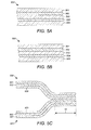
- FIGS. 5A-5C depict cross-sectional views of multilayer films that are suitable for retortable containers described herein.
- FIGS. 1-5C are intended to illustrate embodiments of the invention by way of example, and not by way of limitation.
- the features referred to in these figures are not necessarily drawn to scale and should be understood to present an illustration of the invention and/or principles involved. Some features depicted have been enlarged or distorted relative to others, in order to facilitate explanation and understanding.
- the same reference numbers are used throughout the figures to refer to similar elements and dimensions.
- retortable containers have a peripheral seal proximate at least one edge.
- This edge can result, for example, from heat sealing overlapping portions of a single multilayer film, separate multilayer films, or a multilayer film and a container bottom that may be formed of a rigid or flexible plastic material.
- the container bottom often has a peripheral flange for sealing with the multilayer film, such that it covers the container bottom and thereby encloses the container.
- the retortable container is self-venting, meaning that gases can escape the container, preferably in a controlled manner, when a threshold pressure (e.g ., from about 2 psig to about 5 psig) is reached within the container. Such a pressure is normally attained upon heating the container in a microwave oven to a sufficient temperature to vaporize water or ice in the packaged food and/or cause significant expansion of the enclosed gases.
- a threshold pressure e.g ., from about 2 psig to about 5 psig
- the escape of gases upon heating preferably occurs at defined, self-venting seal regions having a particular construction (e.g ., in terms of seal width) and geometry (e.g ., an inward protrusion) that can be varied to adjust the venting characteristics, including the threshold pressure, as well as the direction and even velocity of the escaping vapors.
- a particular construction e.g ., in terms of seal width
- geometry e.g ., an inward protrusion
- FIGS. 1 and 2 each depict an exemplary self-venting container 10 having peripheral seals 12 extending along the sides and bottom of the container.
- the container depicted in FIG. 2 additionally has a peripheral seal extending along the top of the container.
- Peripheral seals 12 may be formed from heating and compressing overlapping layers of multilayer films at the edges 15 of the container.
- a horizontal gusset may be inserted at a level L (indicated with a horizontal dashed line), near the bottom of container 10 to provide a specific container type, namely a gusseted pouch, having the capability of being free standing.
- aspects of the invention discussed herein are broadly applicable to a wide variety of container types, including pouches having at least one, and preferably at least two, side heat seals.
- pillow pouches are also representative.
- Peripheral seals 12 are characterized as having self-venting seal regions 12A and non-venting seal regions 12B, having differing seal widths along a width dimension that is perpendicular to the edge of the container along which the seal extends.
- Self-venting seal regions are marked in FIGS. 1-4C with diagonal line segments.
- FIGS. 1 and 2 the division between venting and non-venting seal regions 12A, 12B is shown with dashed lines extending through the peripheral seals, perpendicular to the container edges.
- FIG. 3 more clearly shows the basis for this division, with the dashed lines extending through transition point P on the inner boundary 63 of peripheral seal 12.
- gas escaping the container must traverse a minimum distance D across peripheral seal 12 that is at least as great as the minimum non-venting seal width 32 in non-venting seal region 12B.
- gas within self-venting container 10 will require a higher pressure to escape at point P and at all other points along the inner boundary 63B of non-venting seal region 12B, compared to the relatively lower, threshold pressure required for gas to escape at points along the inner boundary 63A of self-venting seal region 12A.
- venting of gas is thereby advantageously confined to one or more specific regions of peripheral seal 12, namely self-venting seal regions 12A.
- the threshold pressure at which venting occurs can be adjusted by varying the characteristics of the seal (e.g ., thickness and seal strength) in self-venting seal region 12A.
- the venting of the container 10, upon exposure to sufficient microwave heating, can therefore be achieved in a controlled and desirable manner, without significant disruption, splatter, and/or loss of the container contents, to the benefit of the end user.
- containers according to embodiments described herein may rely on the seal geometry, including regions of varying thickness, to establish a defined venting "profile.” Venting may be based on a more controllable mechanical, rather than thermal, breakage of peripheral seal 12. Therefore, as discussed above, the peripheral seal preferably does not include any film layer that melts under temperatures typically encountered in microwave cooking (or in retort processing).
- the minimum venting seal width 30 in self-venting seal region 12A is less than the minimum non-venting seal width 32 in non-venting seal region 12B.
- the minimum venting seal width corresponding to the minimum distance across the peripheral seal in self-venting seal region 12A, impacts the threshold pressure, or pressure within the container ( e.g ., under microwave heating conditions), at which the onset of venting (i.e ., the exiting of gases from within the container) occurs.
- minimum venting seal width 30 is generally at most about 5 mm (0.20 in) ( e.g ., from about 0.5 mm (0.020 in) to about 5 mm (0.20 in)) and typically at most about 3.2 mm (0.125 in) ( e.g ., from about 2.4 mm (0.094 in) to about 3.2 mm (0.125 in)).
- the minimum non-venting seal width 32 is generally at least about 1 mm (0.039 in) ( e.g ., from about 1 mm (0.039 in) to about 10 mm (0.39 in)) and typically at least about 3.2 mm (0.125 in) ( e.g ., from about 3.2 mm (0.125 in) to about 7.5 mm (0.30 in)).
- peripheral seal 12 in self-venting seal region 12A forms an inward protrusion relative to peripheral seal 12 in non-venting seal region 12B.
- This protrusion therefore extends toward the interior, for example the center, of the region defined by edges 15 ( FIGS. 1 and 2 ) of container 10 in non-venting seal region 12B.
- FIG. 3 illustrates how this configuration (or inward protrusion) of self-venting seal region 12A, together with line 55 defined by edge 15 of the container in non-venting seal region 12B, define protruded area 57.
- Protruded area 57 defines outer boundary 65 of self-venting seal region 12A.
- the protruded area includes a partial circle 61, which is a substantially complete circle except for gas discharge opening 59.
- the protruded area may include a less complete circle, such as a semi-circle, or may include some other area bounded by a curved shape, such as an ellipse or partial ellipse ( e.g ., a semi-ellipse). Otherwise, the protruded area may be a polygon.
- the materials that are sealed to form edges 15 as discussed above may be absent from protruded area 57, for example in the case where these materials are simply punched out from peripheral seal 12. According to other embodiments, these materials may be present in protruded area 57, but in an unsealed condition, or at least partly unsealed. In this case, the unsealed materials (e.g ., unsealed multilayer films) in protruded area 57 advantageously act as guides to direct exiting (vented) vapors, for example between the unsealed materials through discharge opening 59.
- these exiting vapors will therefore be directed out the side of container 10, substantially in the plane in which peripheral seal 12 resides.
- the positioning of one or more gas discharge openings, rather than between the unsealed materials, may be varied in protruded area 57 to direct vapors upward or downward relative to this plane (e.g ., top and bottom gas discharge openings in protruded area 57 may be used to direct vapors in a plane perpendicular to the plane in which peripheral seal 12 resides).
- the gas discharge opening is preferably smaller (e.g ., of a smaller diameter), based on the minimum distance across this opening, relative to the diameter of a partial circle or relative to the smallest diameter ( e.g ., along the minor axis) of the partial ellipse.
- the gas discharge opening (regardless of the shape of the protruded area) is generally at least about 2 mm (0.079 in) ( e.g ., from about 2 mm (0.079 in) to about 15 mm (0.59 in)), and typically at least about 4 mm (0.16 in) ( e.g ., from about 4 mm (0.16 in) to about 10 mm (0.39 in)).
- the diameter of the partial circle or smallest diameter of the partial ellipse of the protruded area is generally at least about 7.5 mm (0.30 in) ( e.g ., from about 7.5 mm (0.30 in) to about 25 mm (1 in)) and typically at least about 10 mm (0.39 in) ( e.g ., from about 10 mm (0.39 in) to about 20 mm (0.79 in)).
- the use of a smaller gas discharge opening 59, relative to the diameter of the partial circle or smallest diameter of the partial ellipse, can provide for a more "focused" direction of exiting vapors.
- FIGS. 4A-4C illustrate inward protrusions in self-venting seal regions having alternative geometries, including a gas discharge opening ( FIG. 4B ) that is the same as the diameter of a semi-circular protruded area 57 (or the same as an axis of an elliptical protruded area 57).
- the protruded area defined by line 55 and inward protrusion of self-venting seal region 12A, is a polygon having an arrow shape.
- inner boundary 63 of self-venting seal region 12A has a shape that conforms substantially to the shape of the inward protrusion and consequently also to the shape of outer boundary 65.
- the venting seal width is substantially constant over at least a portion of inner and outer boundaries 63, 65 and therefore over at least a portion ( e.g ., the majority of, and possibly all) of the self-venting seal region.
- This substantially constant venting seal width corresponds to the minimum venting seal width 30.
- the venting seal width varies over at least a portion ( e.g ., the majority of, and possibly all) of the self-venting region.
- the minimum venting seal width 30 may correspond to several discreet points X, Y, Z, on inner boundary 63, at which mechanical breakage of the seal is likely to occur, upon exposure to pressure and heat from within the container, due to microwaving of its contents.
- the protruded area 57 can include a partial circle or a partial ellipse, with inner boundary 63 of self-venting seal region 12A being formed by line segments.
- Such films relate to multilayer films used in forming one or both sides of the containers described above, and particularly one or both sides of the peripheral seal.
- the ability of such films to withstand retort operations generally requires all film layers to have a sufficiently high melting point.
- preferably such films do not include any film layer having a melting temperature of less than about 90°C (194°F), less than about 100°C (212°F), or even less than about 110°C (230°F).
- the individual components of the blends may have melting temperatures that do not meet these requirements, as long as the blend itself has a sufficiently high melting temperature.
- the multilayer films as well as containers having such films, preferably have seal strength, stability, heat resistance, and oxygen and water vapor transmission properties that allow them to be subjected to retort conditions without loss of desired functional characteristics.
- the container has a seal strength generally from about 10 N/15 mm (3.8 lb/in) to about 200 N/15 mm (75 lb/in), and typically from about 40 N/15 mm (15 lb/in) to about 80 N/15 mm (30 lb/in), according to ASTM-F88 with a crosshead speed of 2.12 cm/sec (5 in/min).
- high seal strength stability of the container is also exhibited, based on a loss in seal strength of generally less than about 35%, typically less than about 20%, and often less than about 10%, upon being subjected to conditions mimicking a retort heat treatment.
- Representative conditions mimicking a retort heat treatment include exposure of the container to (1) a temperature of 110°C (230°F) for 30 minutes, (2) a temperature of 110°C (230°F) for 60 minutes, (3) a temperature of 135°C (275°F) for 30 minutes, or (4) a temperature of 135°C (275°F) for 60 minutes.
- multilayer films described herein also have acceptable heat resistance, in terms of not undergoing delamination.
- no delamination of the film structure is observed after the film is subjected to 100°C (212°F) for 30 minutes, or even for 60 minutes.
- Further properties of representative films include a barrier-oxygen transmission rate of generally from about 0.16 cc/M 2 /day (0.01 cc/100 in 2 /day) to about 62 cc/M 2 /day (4 cc/100 in 2 /day), and typically from about 0.16 cc/M 2 /day (0.01 cc/100 in 2 /day) to about 1.6 cc/M 2 /day (0.1 cc/100 in 2 /day) at a temperature of 23°C (73°F), and/or a barrier-water vapor transmission rate of generally from about 0.47 g/M 2 /day (0.03 g/100 in 2 /day) to about 7.8 g/M 2 /day (0.5 g/100 in 2 /day), and typically from about 0.47 g/M 2 /day (0.03 g/100 in 2 /day) to about 3.9 cc/M 2 /day (0.25 g/100 in 2 /day) at
- Multilayer films are also in compliance with regulations set forth under 21 C.F.R. ⁇ 177.1390, hereby incorporated by reference.
- the multilayer film comprises a sealing layer that forms a peripheral seal of the container, including the self-venting and non-venting seal regions, as described above.
- this sealing layer is bonded to a suitable base material, such as a rigid or flexible container bottom, for example comprising polypropylene or polyethylene.
- the base material may also be another multilayer film of the same type or of a different type. For example, if the multilayer film is folded upon itself and heat sealed at overlapping edges to provide a container volume bounded by non-sealed areas of the film, the multilayer film and base material, as well as the sealing layers being bonded, are necessarily the same.
- the sealing layer is the innermost layer, facing the interior of the container and often contacting the container contents, such as food, directly.
- a preferred sealing layer comprises ( e.g ., in a major amount of greater than 50% by weight), or consists essentially of (1) a polypropylene or (ii) a blend of polypropylene and at least one other polyolefin.
- Polyolefins include polyolefin plastomers, such as, for example polyethylene that may be blended in the sealing layer.
- the sealing layer may also comprise ( e.g ., in a major amount of greater than 50% by weight), or consist essentially of (i) a cast retortable grade polypropylene (ii) a coextruded polypropylene polymer or copolymer, or (iii) a blend of a coextruded polypropylene polymer or copolymer and at least one other polyolefin.
- the sealing layer comprises 100% by weight of cast retortable grade polypropylene.
- a particular, representative cast retortable grade polypropylene has a density of about 0.9 g/cm 3 ( e.g ., in the range from about 0.85 g/cm 3 to about 0.95 g/cm 3 ) and melt flow index of 2.1 g/10 min ( e.g ., in the range from about 1.9 g/10 min to about 2.3 g/10 min), such as, for example, KAP High Performance CPP (Amcor Flexibles Venturina S.r.l., Campiglia Marittima, Italy).
- the thickness of the sealing layer is generally from about 10 ⁇ m (0.39 mils) to about 500 ⁇ m (20 mils), and typically from about 50 ⁇ m (2 mils) to about 200 ⁇ m (7.9 mils).
- the multilayer film further comprises an outer layer facing the exterior of the container and disposed furthest from the container contents.
- the outer layer and sealing layer are adjacent and bonded directly to one another.
- the outer and sealing layers are not adjacent, but separated by these further layers, being disposed therebetween.
- a representative outer layer comprises ( e.g ., in a major amount of greater than 50% by weight), or consists essentially of, (i) biaxially oriented nylon or (ii) biaxially oriented polyethylene terephthalate.
- a suitable biaxially oriented nylon is Nylon 6 such as Filmon BXS Nylon 6 (CFP Flexible Packaging S.p.A., Cesano Maderno, IT).
- a suitable biaxially oriented polyethylene terephthalate source is IB-PET-RB (Dai Nippon Printing Co., LTD., Tokyo, Japan).
- the thickness of the outer layer is generally from about 1 ⁇ m (0.039 mils) to about 100 ⁇ m (3.9 mils), and typically from about 7.5 ⁇ m (0.30 mils) to about 25 ⁇ m (0.98 mils).
- an adhesive layer or a primer layer may be disposed between the outer and sealant layers.
- the adhesive or primer may be adjacent both the outer and sealant layers ( i.e ., sandwiched between these layers).
- Suitable adhesives include 2-component polyurethanes such as Adcote TM 812/9L10 (Rohm & Haas Company, Philadelphia, PA USA), having a solids content of about 32%.
- Suitable primers include aqueous resin dispersions such as MICA A-131 (Mica Corporation, Shelton, CT USA), having a solids content of about 5%.
- such multilayer films may also comprise (i) one or more further biaxially oriented nylon or biaxially oriented polyethylene terephthalate layers, having a layer thickness as described above with respect to the outer layer, and/or (ii) one or more further adhesive or primer layers, as described above.
- such multilayer films may also comprise functional layers, including functional barrier layers such as aluminum foil.
- the thickness of a functional layer when used, is generally from about 1 ⁇ m (0.039 mils) to about 100 ⁇ m (3.9 mils), and typically from about 5 ⁇ m (0.20 mils) to about 10 ⁇ m (0.39 mils).
- the total thickness of a representative, multilayer film used in a self-venting, retortable container, as described herein, is generally from about 51 ⁇ m (2 mils) to about 380 ⁇ m (15 mils), and typically from about 74 ⁇ m (2.9 mils) to about 150 ⁇ m (6 mils).
- a cross-sectional view of a representative 5-layer film 500 is depicted in FIG. 5A , having the following layers, in order: an outer layer of biaxially oriented polyethylene terephthalate 501, a polyurethane adhesive layer 502, a biaxially oriented nylon layer 503, a second polyurethane adhesive layer 504, and a polypropylene sealant layer 505.
- FIG. 5A A cross-sectional view of another representative 5-layer film 500, for example, is depicted in FIG.
- an outer layer of biaxially oriented polyethylene terephthalate 501 having the following layers, in order: an outer layer of biaxially oriented polyethylene terephthalate 501, a polyurethane adhesive layer 502, an aluminum foil layer 510, a second polyurethane adhesive layer 504, and a polypropylene sealant layer 505.
- FIG. 5C depicts the sealing between adjacent sealant layers 505, in either the self-venting region or non-venting region of peripheral seal 12 of a container as described herein. Sealing occurs between two identical 3-layer films, or otherwise a single 3-layer film that has been folded ( e.g ., with the fold not shown but occurring beyond the left side of the page).
- the films also include adhesive layers 502 and outer layers 501, as described above.
- aspects of the invention are directed to self-venting, retortable containers and multilayer films suitable for use in such containers.
- Characteristics of the multilayer films, in combination with characteristics of the self-venting seal regions, provide containers having desirable venting properties as described herein.
- a film for use in non-retortable packing was prepared and evaluated for seal strength properties according to ASTM-F88 with a crosshead speed of 2.12 cm/sec (5 in/min).
- the film had the following structure, from the outer to the inner (sealing or food contact) layer:
- Table 3 WATER VAPOR TRANSMISSION RATE cc/M 2 /day cc/100in 2 /day Caliper mils front 1.84 0.119 4.39 back 2.68 0.173 4.32 front 1.41 0.091 4.37 back 2.85 0.184 4.25 front 2.18 0.141 4.61 back 1.27 0.082 4.40
Landscapes
- Engineering & Computer Science (AREA)
- Mechanical Engineering (AREA)
- Life Sciences & Earth Sciences (AREA)
- Food Science & Technology (AREA)
- Packages (AREA)
- Laminated Bodies (AREA)
- Bag Frames (AREA)
- Package Specialized In Special Use (AREA)
Applications Claiming Priority (1)
| Application Number | Priority Date | Filing Date | Title |
|---|---|---|---|
| US13/218,112 US20130048636A1 (en) | 2011-08-25 | 2011-08-25 | Flexible, self-venting retortable container |
Publications (1)
| Publication Number | Publication Date |
|---|---|
| EP2562099A1 true EP2562099A1 (fr) | 2013-02-27 |
Family
ID=46419966
Family Applications (1)
| Application Number | Title | Priority Date | Filing Date |
|---|---|---|---|
| EP12174218A Withdrawn EP2562099A1 (fr) | 2011-08-25 | 2012-06-28 | Appareil de circuit de réfrigération et procédé de fonctionnement de celui-ci |
Country Status (9)
| Country | Link |
|---|---|
| US (1) | US20130048636A1 (fr) |
| EP (1) | EP2562099A1 (fr) |
| JP (1) | JP2013043699A (fr) |
| KR (1) | KR20130022371A (fr) |
| CN (1) | CN102951351A (fr) |
| AU (1) | AU2012216343B2 (fr) |
| BR (1) | BR102012017371A2 (fr) |
| CA (1) | CA2786057A1 (fr) |
| MX (1) | MX2012009877A (fr) |
Cited By (1)
| Publication number | Priority date | Publication date | Assignee | Title |
|---|---|---|---|---|
| EP3517457A4 (fr) * | 2016-09-23 | 2020-06-03 | Toyo Seikan Co., Ltd. | Sac d'emballage pour un chauffage de four à micro-ondes |
Families Citing this family (28)
| Publication number | Priority date | Publication date | Assignee | Title |
|---|---|---|---|---|
| US9352893B2 (en) * | 2012-02-17 | 2016-05-31 | Amcor Flexibles Transpac N.V. | Self-venting package |
| KR101687885B1 (ko) * | 2012-03-07 | 2016-12-19 | 도판 인사츠 가부시키가이샤 | 증기 배출 스탠딩 파우치 및 내용물 봉입 스탠딩 파우치 |
| JP6221986B2 (ja) * | 2013-11-20 | 2017-11-01 | 大日本印刷株式会社 | パウチ |
| JP6425122B2 (ja) * | 2014-10-06 | 2018-11-21 | 大日本印刷株式会社 | パウチ |
| JP6425123B2 (ja) * | 2014-10-06 | 2018-11-21 | 大日本印刷株式会社 | パウチ |
| US10569950B2 (en) | 2015-12-31 | 2020-02-25 | Bemis Company, Inc. | Self-venting bag-in-box package |
| JP2017159911A (ja) * | 2016-03-07 | 2017-09-14 | 大日本印刷株式会社 | 電子レンジ加熱用包装体 |
| EP3466836B1 (fr) * | 2016-06-02 | 2025-03-19 | Toppan Printing Co., Ltd. | Poche |
| GB201610432D0 (en) * | 2016-06-15 | 2016-07-27 | Mars Inc | Easy Peel Pouch |
| JP7182351B2 (ja) * | 2016-10-03 | 2022-12-02 | 凸版印刷株式会社 | スタンディングパウチ及びその製造方法 |
| JP6226100B2 (ja) * | 2017-05-15 | 2017-11-08 | 大日本印刷株式会社 | パウチ |
| JP6222394B2 (ja) * | 2017-05-15 | 2017-11-01 | 大日本印刷株式会社 | パウチ |
| JP6229964B2 (ja) * | 2017-05-15 | 2017-11-15 | 大日本印刷株式会社 | パウチ |
| JP6496355B2 (ja) * | 2017-05-19 | 2019-04-03 | 大日本印刷株式会社 | パウチ |
| AU201717553S (en) | 2017-06-15 | 2018-01-09 | Mars Inc | Flexible Package |
| USD864755S1 (en) | 2017-06-15 | 2019-10-29 | Mars, Incorporated | Flexible package |
| JP7309319B2 (ja) * | 2017-12-20 | 2023-07-18 | 大日本印刷株式会社 | パウチ |
| JP2018111539A (ja) * | 2018-04-23 | 2018-07-19 | 大日本印刷株式会社 | パウチ |
| JP2018131271A (ja) * | 2018-04-23 | 2018-08-23 | 大日本印刷株式会社 | パウチ |
| USD894012S1 (en) | 2018-08-23 | 2020-08-25 | Mars, Incorporated | Pouch |
| CN109110302B (zh) * | 2018-10-11 | 2024-02-06 | 上海领海挪华企业发展有限公司 | 适用于极地的存储箱 |
| JP6641651B2 (ja) * | 2019-04-24 | 2020-02-05 | 大日本印刷株式会社 | パウチ |
| JP6614521B2 (ja) * | 2019-04-26 | 2019-12-04 | 大日本印刷株式会社 | パウチ |
| CN114096411A (zh) | 2019-05-17 | 2022-02-25 | 阿姆科挠性物品北美公司 | 可再循环膜和包装 |
| US20210155388A1 (en) * | 2019-11-25 | 2021-05-27 | Sonoco Development, Inc. | Flexible lidding film |
| JP7721891B2 (ja) * | 2020-12-11 | 2025-08-13 | 住友ベークライト株式会社 | 包装材料 |
| CN113291606A (zh) * | 2021-05-27 | 2021-08-24 | 金石包装(嘉兴)有限公司 | 一种适合微波加热的包装袋 |
| US12509291B2 (en) * | 2023-10-24 | 2025-12-30 | Amcor Flexibles North America, Inc. | Microwave package with low pressure venting feature |
Citations (5)
| Publication number | Priority date | Publication date | Assignee | Title |
|---|---|---|---|---|
| US6596355B1 (en) | 2000-04-06 | 2003-07-22 | Dai Nippon Printing Co., Ltd. | Sealable package for heating in a microwave oven |
| US20050255200A1 (en) * | 2004-05-17 | 2005-11-17 | Dai Nippon Printing Co., Ltd. | Food packaging bag, food-packaged body, and method for manufacturing the same |
| EP1880954A1 (fr) * | 2005-05-02 | 2008-01-23 | Toyo Seikan Kaisha, Ltd. | Sachet d'emballage pour four a micro-ondes |
| US20100266732A1 (en) * | 2009-04-20 | 2010-10-21 | Fres-Co System Usa, Inc. | Microwavable self-venting package |
| US20110100984A1 (en) * | 2009-11-05 | 2011-05-05 | Wonji Co., Ltd. | Vinyl pouch equipped with internal pressure discharge unit usable in microwave oven to prevent contents from being leaked and being dried |
Family Cites Families (4)
| Publication number | Priority date | Publication date | Assignee | Title |
|---|---|---|---|---|
| US3185579A (en) * | 1955-01-05 | 1965-05-25 | Dehne Rudolf | Packaging of freshly baked bread |
| US3937396A (en) * | 1974-01-18 | 1976-02-10 | Schneider William S | Valve for vented package |
| JP2005320023A (ja) * | 2004-05-07 | 2005-11-17 | Toyo Seikan Kaisha Ltd | 平置き型の電子レンジ用包装袋 |
| EP1870350B1 (fr) * | 2005-04-04 | 2013-04-03 | Dai Nippon Printing Co., Ltd. | Sac d'emballage pour four à micro-ondes |
-
2011
- 2011-08-25 US US13/218,112 patent/US20130048636A1/en not_active Abandoned
-
2012
- 2012-06-28 EP EP12174218A patent/EP2562099A1/fr not_active Withdrawn
- 2012-07-10 KR KR1020120074874A patent/KR20130022371A/ko not_active Withdrawn
- 2012-07-13 BR BR102012017371-9A patent/BR102012017371A2/pt not_active IP Right Cessation
- 2012-07-24 CN CN2012102607170A patent/CN102951351A/zh active Pending
- 2012-08-13 CA CA2786057A patent/CA2786057A1/fr not_active Abandoned
- 2012-08-22 AU AU2012216343A patent/AU2012216343B2/en active Active
- 2012-08-24 MX MX2012009877A patent/MX2012009877A/es not_active Application Discontinuation
- 2012-08-24 JP JP2012185648A patent/JP2013043699A/ja active Pending
Patent Citations (5)
| Publication number | Priority date | Publication date | Assignee | Title |
|---|---|---|---|---|
| US6596355B1 (en) | 2000-04-06 | 2003-07-22 | Dai Nippon Printing Co., Ltd. | Sealable package for heating in a microwave oven |
| US20050255200A1 (en) * | 2004-05-17 | 2005-11-17 | Dai Nippon Printing Co., Ltd. | Food packaging bag, food-packaged body, and method for manufacturing the same |
| EP1880954A1 (fr) * | 2005-05-02 | 2008-01-23 | Toyo Seikan Kaisha, Ltd. | Sachet d'emballage pour four a micro-ondes |
| US20100266732A1 (en) * | 2009-04-20 | 2010-10-21 | Fres-Co System Usa, Inc. | Microwavable self-venting package |
| US20110100984A1 (en) * | 2009-11-05 | 2011-05-05 | Wonji Co., Ltd. | Vinyl pouch equipped with internal pressure discharge unit usable in microwave oven to prevent contents from being leaked and being dried |
Cited By (1)
| Publication number | Priority date | Publication date | Assignee | Title |
|---|---|---|---|---|
| EP3517457A4 (fr) * | 2016-09-23 | 2020-06-03 | Toyo Seikan Co., Ltd. | Sac d'emballage pour un chauffage de four à micro-ondes |
Also Published As
| Publication number | Publication date |
|---|---|
| CA2786057A1 (fr) | 2013-02-25 |
| JP2013043699A (ja) | 2013-03-04 |
| US20130048636A1 (en) | 2013-02-28 |
| AU2012216343A1 (en) | 2013-03-14 |
| AU2012216343B2 (en) | 2014-08-07 |
| CN102951351A (zh) | 2013-03-06 |
| MX2012009877A (es) | 2013-03-15 |
| BR102012017371A2 (pt) | 2014-03-18 |
| KR20130022371A (ko) | 2013-03-06 |
Similar Documents
| Publication | Publication Date | Title |
|---|---|---|
| AU2012216343B2 (en) | Flexible, self-venting retortable container | |
| EP2925633B1 (fr) | Contenant souple destiné au remplissage à chaud, à autoscellage et autoventilation | |
| US7812293B2 (en) | Freezable/microwavable packaging films and venting packages | |
| US20190047751A1 (en) | Flexible laminate structure with integrated one-way valve | |
| US4311742A (en) | Retort-sterilizable laminated pouch comprising a flexible gas-barrier substrate and blended crystalline olefin layer | |
| US9126734B2 (en) | Self venting steam valve for flexible packaging bags and pouches used in cooking of foods | |
| JP2009214892A (ja) | 電子レンジ加熱用包装袋 | |
| JP2011173628A (ja) | 電子レンジ用調理袋 | |
| JP2022047354A (ja) | 包装用積層体 | |
| EP2592012B1 (fr) | Système de fermeture | |
| US20220289458A1 (en) | Multi-compartment retort package | |
| JP6326911B2 (ja) | 電子レンジ用容器及び電子レンジ用包装体 | |
| JP6863417B2 (ja) | スキンパック包装体 | |
| JP2019142573A (ja) | 包装袋 | |
| JP2017171361A (ja) | 包装袋 | |
| EP0919365B1 (fr) | Feuille composite et récipient scellé | |
| KR20210060584A (ko) | 개봉 용이성 포장 백 그리고 가스 배리어성을 구비한 개봉 용이성 적층 필름 및 파우치 | |
| JP7124945B2 (ja) | 包装体の製造方法 | |
| JP2019038593A (ja) | 包装袋 | |
| JPH0691808A (ja) | 機能性食品包装材料及びそれを用いた食品容器 | |
| KR20170136870A (ko) | 전자 레인지용 음식물 포장용 밀봉 봉투 |
Legal Events
| Date | Code | Title | Description |
|---|---|---|---|
| PUAI | Public reference made under article 153(3) epc to a published international application that has entered the european phase |
Free format text: ORIGINAL CODE: 0009012 |
|
| AK | Designated contracting states |
Kind code of ref document: A1 Designated state(s): AL AT BE BG CH CY CZ DE DK EE ES FI FR GB GR HR HU IE IS IT LI LT LU LV MC MK MT NL NO PL PT RO RS SE SI SK SM TR |
|
| AX | Request for extension of the european patent |
Extension state: BA ME |
|
| 17P | Request for examination filed |
Effective date: 20130503 |
|
| 17Q | First examination report despatched |
Effective date: 20131016 |
|
| STAA | Information on the status of an ep patent application or granted ep patent |
Free format text: STATUS: THE APPLICATION IS DEEMED TO BE WITHDRAWN |
|
| 18D | Application deemed to be withdrawn |
Effective date: 20141211 |