EP2563570B1 - Élément intérieur à structure superficielle artificielle et procédé pour le produire - Google Patents
Élément intérieur à structure superficielle artificielle et procédé pour le produire Download PDFInfo
- Publication number
- EP2563570B1 EP2563570B1 EP11716902.9A EP11716902A EP2563570B1 EP 2563570 B1 EP2563570 B1 EP 2563570B1 EP 11716902 A EP11716902 A EP 11716902A EP 2563570 B1 EP2563570 B1 EP 2563570B1
- Authority
- EP
- European Patent Office
- Prior art keywords
- composite element
- fiber composite
- interior component
- layer
- fiber
- Prior art date
- Legal status (The legal status is an assumption and is not a legal conclusion. Google has not performed a legal analysis and makes no representation as to the accuracy of the status listed.)
- Active
Links
Images



Classifications
-
- B—PERFORMING OPERATIONS; TRANSPORTING
- B29—WORKING OF PLASTICS; WORKING OF SUBSTANCES IN A PLASTIC STATE IN GENERAL
- B29C—SHAPING OR JOINING OF PLASTICS; SHAPING OF MATERIAL IN A PLASTIC STATE, NOT OTHERWISE PROVIDED FOR; AFTER-TREATMENT OF THE SHAPED PRODUCTS, e.g. REPAIRING
- B29C70/00—Shaping composites, i.e. plastics material comprising reinforcements, fillers or preformed parts, e.g. inserts
- B29C70/04—Shaping composites, i.e. plastics material comprising reinforcements, fillers or preformed parts, e.g. inserts comprising reinforcements only, e.g. self-reinforcing plastics
- B29C70/06—Fibrous reinforcements only
- B29C70/08—Fibrous reinforcements only comprising combinations of different forms of fibrous reinforcements incorporated in matrix material, forming one or more layers, and with or without non-reinforced layers
- B29C70/086—Fibrous reinforcements only comprising combinations of different forms of fibrous reinforcements incorporated in matrix material, forming one or more layers, and with or without non-reinforced layers and with one or more layers of pure plastics material, e.g. foam layers
-
- B—PERFORMING OPERATIONS; TRANSPORTING
- B27—WORKING OR PRESERVING WOOD OR SIMILAR MATERIAL; NAILING OR STAPLING MACHINES IN GENERAL
- B27N—MANUFACTURE BY DRY PROCESSES OF ARTICLES, WITH OR WITHOUT ORGANIC BINDING AGENTS, MADE FROM PARTICLES OR FIBRES CONSISTING OF WOOD OR OTHER LIGNOCELLULOSIC OR LIKE ORGANIC MATERIAL
- B27N3/00—Manufacture of substantially flat articles, e.g. boards, from particles or fibres
- B27N3/08—Moulding or pressing
- B27N3/10—Moulding of mats
- B27N3/12—Moulding of mats from fibres
-
- B—PERFORMING OPERATIONS; TRANSPORTING
- B29—WORKING OF PLASTICS; WORKING OF SUBSTANCES IN A PLASTIC STATE IN GENERAL
- B29C—SHAPING OR JOINING OF PLASTICS; SHAPING OF MATERIAL IN A PLASTIC STATE, NOT OTHERWISE PROVIDED FOR; AFTER-TREATMENT OF THE SHAPED PRODUCTS, e.g. REPAIRING
- B29C70/00—Shaping composites, i.e. plastics material comprising reinforcements, fillers or preformed parts, e.g. inserts
- B29C70/04—Shaping composites, i.e. plastics material comprising reinforcements, fillers or preformed parts, e.g. inserts comprising reinforcements only, e.g. self-reinforcing plastics
- B29C70/28—Shaping operations therefor
- B29C70/40—Shaping or impregnating by compression not applied
- B29C70/42—Shaping or impregnating by compression not applied for producing articles of definite length, i.e. discrete articles
- B29C70/46—Shaping or impregnating by compression not applied for producing articles of definite length, i.e. discrete articles using matched moulds, e.g. for deforming sheet moulding compounds [SMC] or prepregs
-
- B—PERFORMING OPERATIONS; TRANSPORTING
- B32—LAYERED PRODUCTS
- B32B—LAYERED PRODUCTS, i.e. PRODUCTS BUILT-UP OF STRATA OF FLAT OR NON-FLAT, e.g. CELLULAR OR HONEYCOMB, FORM
- B32B15/00—Layered products comprising a layer of metal
- B32B15/04—Layered products comprising a layer of metal comprising metal as the main or only constituent of a layer, which is next to another layer of the same or of a different material
- B32B15/08—Layered products comprising a layer of metal comprising metal as the main or only constituent of a layer, which is next to another layer of the same or of a different material of synthetic resin
-
- B—PERFORMING OPERATIONS; TRANSPORTING
- B32—LAYERED PRODUCTS
- B32B—LAYERED PRODUCTS, i.e. PRODUCTS BUILT-UP OF STRATA OF FLAT OR NON-FLAT, e.g. CELLULAR OR HONEYCOMB, FORM
- B32B27/00—Layered products comprising a layer of synthetic resin
- B32B27/06—Layered products comprising a layer of synthetic resin as the main or only constituent of a layer, which is next to another layer of the same or of a different material
- B32B27/08—Layered products comprising a layer of synthetic resin as the main or only constituent of a layer, which is next to another layer of the same or of a different material of synthetic resin
-
- B—PERFORMING OPERATIONS; TRANSPORTING
- B32—LAYERED PRODUCTS
- B32B—LAYERED PRODUCTS, i.e. PRODUCTS BUILT-UP OF STRATA OF FLAT OR NON-FLAT, e.g. CELLULAR OR HONEYCOMB, FORM
- B32B5/00—Layered products characterised by the non- homogeneity or physical structure, i.e. comprising a fibrous, filamentary, particulate or foam layer; Layered products characterised by having a layer differing constitutionally or physically in different parts
- B32B5/02—Layered products characterised by the non- homogeneity or physical structure, i.e. comprising a fibrous, filamentary, particulate or foam layer; Layered products characterised by having a layer differing constitutionally or physically in different parts characterised by structural features of a fibrous or filamentary layer
- B32B5/022—Non-woven fabric
-
- B—PERFORMING OPERATIONS; TRANSPORTING
- B32—LAYERED PRODUCTS
- B32B—LAYERED PRODUCTS, i.e. PRODUCTS BUILT-UP OF STRATA OF FLAT OR NON-FLAT, e.g. CELLULAR OR HONEYCOMB, FORM
- B32B5/00—Layered products characterised by the non- homogeneity or physical structure, i.e. comprising a fibrous, filamentary, particulate or foam layer; Layered products characterised by having a layer differing constitutionally or physically in different parts
- B32B5/02—Layered products characterised by the non- homogeneity or physical structure, i.e. comprising a fibrous, filamentary, particulate or foam layer; Layered products characterised by having a layer differing constitutionally or physically in different parts characterised by structural features of a fibrous or filamentary layer
- B32B5/024—Woven fabric
-
- B—PERFORMING OPERATIONS; TRANSPORTING
- B32—LAYERED PRODUCTS
- B32B—LAYERED PRODUCTS, i.e. PRODUCTS BUILT-UP OF STRATA OF FLAT OR NON-FLAT, e.g. CELLULAR OR HONEYCOMB, FORM
- B32B5/00—Layered products characterised by the non- homogeneity or physical structure, i.e. comprising a fibrous, filamentary, particulate or foam layer; Layered products characterised by having a layer differing constitutionally or physically in different parts
- B32B5/02—Layered products characterised by the non- homogeneity or physical structure, i.e. comprising a fibrous, filamentary, particulate or foam layer; Layered products characterised by having a layer differing constitutionally or physically in different parts characterised by structural features of a fibrous or filamentary layer
- B32B5/08—Layered products characterised by the non- homogeneity or physical structure, i.e. comprising a fibrous, filamentary, particulate or foam layer; Layered products characterised by having a layer differing constitutionally or physically in different parts characterised by structural features of a fibrous or filamentary layer the fibres or filaments of a layer being of different substances, e.g. conjugate fibres, mixture of different fibres
-
- B—PERFORMING OPERATIONS; TRANSPORTING
- B32—LAYERED PRODUCTS
- B32B—LAYERED PRODUCTS, i.e. PRODUCTS BUILT-UP OF STRATA OF FLAT OR NON-FLAT, e.g. CELLULAR OR HONEYCOMB, FORM
- B32B5/00—Layered products characterised by the non- homogeneity or physical structure, i.e. comprising a fibrous, filamentary, particulate or foam layer; Layered products characterised by having a layer differing constitutionally or physically in different parts
- B32B5/22—Layered products characterised by the non- homogeneity or physical structure, i.e. comprising a fibrous, filamentary, particulate or foam layer; Layered products characterised by having a layer differing constitutionally or physically in different parts characterised by the presence of two or more layers which are next to each other and are fibrous, filamentary, formed of particles or foamed
- B32B5/24—Layered products characterised by the non- homogeneity or physical structure, i.e. comprising a fibrous, filamentary, particulate or foam layer; Layered products characterised by having a layer differing constitutionally or physically in different parts characterised by the presence of two or more layers which are next to each other and are fibrous, filamentary, formed of particles or foamed one layer being a fibrous or filamentary layer
- B32B5/26—Layered products characterised by the non- homogeneity or physical structure, i.e. comprising a fibrous, filamentary, particulate or foam layer; Layered products characterised by having a layer differing constitutionally or physically in different parts characterised by the presence of two or more layers which are next to each other and are fibrous, filamentary, formed of particles or foamed one layer being a fibrous or filamentary layer another layer next to it also being fibrous or filamentary
-
- B—PERFORMING OPERATIONS; TRANSPORTING
- B32—LAYERED PRODUCTS
- B32B—LAYERED PRODUCTS, i.e. PRODUCTS BUILT-UP OF STRATA OF FLAT OR NON-FLAT, e.g. CELLULAR OR HONEYCOMB, FORM
- B32B7/00—Layered products characterised by the relation between layers; Layered products characterised by the relative orientation of features between layers, or by the relative values of a measurable parameter between layers, i.e. products comprising layers having different physical, chemical or physicochemical properties; Layered products characterised by the interconnection of layers
- B32B7/04—Interconnection of layers
- B32B7/12—Interconnection of layers using interposed adhesives or interposed materials with bonding properties
-
- B—PERFORMING OPERATIONS; TRANSPORTING
- B29—WORKING OF PLASTICS; WORKING OF SUBSTANCES IN A PLASTIC STATE IN GENERAL
- B29K—INDEXING SCHEME ASSOCIATED WITH SUBCLASSES B29B, B29C OR B29D, RELATING TO MOULDING MATERIALS OR TO MATERIALS FOR MOULDS, REINFORCEMENTS, FILLERS OR PREFORMED PARTS, e.g. INSERTS
- B29K2311/00—Use of natural products or their composites, not provided for in groups B29K2201/00 - B29K2309/00, as reinforcement
- B29K2311/10—Natural fibres, e.g. wool or cotton
-
- B—PERFORMING OPERATIONS; TRANSPORTING
- B29—WORKING OF PLASTICS; WORKING OF SUBSTANCES IN A PLASTIC STATE IN GENERAL
- B29K—INDEXING SCHEME ASSOCIATED WITH SUBCLASSES B29B, B29C OR B29D, RELATING TO MOULDING MATERIALS OR TO MATERIALS FOR MOULDS, REINFORCEMENTS, FILLERS OR PREFORMED PARTS, e.g. INSERTS
- B29K2711/00—Use of natural products or their composites, not provided for in groups B29K2601/00 - B29K2709/00, for preformed parts, e.g. for inserts
- B29K2711/14—Wood, e.g. woodboard or fibreboard
-
- B—PERFORMING OPERATIONS; TRANSPORTING
- B29—WORKING OF PLASTICS; WORKING OF SUBSTANCES IN A PLASTIC STATE IN GENERAL
- B29L—INDEXING SCHEME ASSOCIATED WITH SUBCLASS B29C, RELATING TO PARTICULAR ARTICLES
- B29L2031/00—Other particular articles
- B29L2031/30—Vehicles, e.g. ships or aircraft, or body parts thereof
- B29L2031/3005—Body finishings
-
- B—PERFORMING OPERATIONS; TRANSPORTING
- B29—WORKING OF PLASTICS; WORKING OF SUBSTANCES IN A PLASTIC STATE IN GENERAL
- B29L—INDEXING SCHEME ASSOCIATED WITH SUBCLASS B29C, RELATING TO PARTICULAR ARTICLES
- B29L2031/00—Other particular articles
- B29L2031/30—Vehicles, e.g. ships or aircraft, or body parts thereof
- B29L2031/3055—Cars
-
- B—PERFORMING OPERATIONS; TRANSPORTING
- B32—LAYERED PRODUCTS
- B32B—LAYERED PRODUCTS, i.e. PRODUCTS BUILT-UP OF STRATA OF FLAT OR NON-FLAT, e.g. CELLULAR OR HONEYCOMB, FORM
- B32B2255/00—Coating on the layer surface
- B32B2255/02—Coating on the layer surface on fibrous or filamentary layer
-
- B—PERFORMING OPERATIONS; TRANSPORTING
- B32—LAYERED PRODUCTS
- B32B—LAYERED PRODUCTS, i.e. PRODUCTS BUILT-UP OF STRATA OF FLAT OR NON-FLAT, e.g. CELLULAR OR HONEYCOMB, FORM
- B32B2255/00—Coating on the layer surface
- B32B2255/10—Coating on the layer surface on synthetic resin layer or on natural or synthetic rubber layer
-
- B—PERFORMING OPERATIONS; TRANSPORTING
- B32—LAYERED PRODUCTS
- B32B—LAYERED PRODUCTS, i.e. PRODUCTS BUILT-UP OF STRATA OF FLAT OR NON-FLAT, e.g. CELLULAR OR HONEYCOMB, FORM
- B32B2255/00—Coating on the layer surface
- B32B2255/20—Inorganic coating
- B32B2255/205—Metallic coating
-
- B—PERFORMING OPERATIONS; TRANSPORTING
- B32—LAYERED PRODUCTS
- B32B—LAYERED PRODUCTS, i.e. PRODUCTS BUILT-UP OF STRATA OF FLAT OR NON-FLAT, e.g. CELLULAR OR HONEYCOMB, FORM
- B32B2260/00—Layered product comprising an impregnated, embedded, or bonded layer wherein the layer comprises an impregnation, embedding, or binder material
- B32B2260/02—Composition of the impregnated, bonded or embedded layer
- B32B2260/021—Fibrous or filamentary layer
-
- B—PERFORMING OPERATIONS; TRANSPORTING
- B32—LAYERED PRODUCTS
- B32B—LAYERED PRODUCTS, i.e. PRODUCTS BUILT-UP OF STRATA OF FLAT OR NON-FLAT, e.g. CELLULAR OR HONEYCOMB, FORM
- B32B2260/00—Layered product comprising an impregnated, embedded, or bonded layer wherein the layer comprises an impregnation, embedding, or binder material
- B32B2260/04—Impregnation, embedding, or binder material
- B32B2260/046—Synthetic resin
-
- B—PERFORMING OPERATIONS; TRANSPORTING
- B32—LAYERED PRODUCTS
- B32B—LAYERED PRODUCTS, i.e. PRODUCTS BUILT-UP OF STRATA OF FLAT OR NON-FLAT, e.g. CELLULAR OR HONEYCOMB, FORM
- B32B2262/00—Composition or structural features of fibres which form a fibrous or filamentary layer or are present as additives
- B32B2262/02—Synthetic macromolecular fibres
- B32B2262/0246—Acrylic resin fibres
-
- B—PERFORMING OPERATIONS; TRANSPORTING
- B32—LAYERED PRODUCTS
- B32B—LAYERED PRODUCTS, i.e. PRODUCTS BUILT-UP OF STRATA OF FLAT OR NON-FLAT, e.g. CELLULAR OR HONEYCOMB, FORM
- B32B2262/00—Composition or structural features of fibres which form a fibrous or filamentary layer or are present as additives
- B32B2262/02—Synthetic macromolecular fibres
- B32B2262/0253—Polyolefin fibres
-
- B—PERFORMING OPERATIONS; TRANSPORTING
- B32—LAYERED PRODUCTS
- B32B—LAYERED PRODUCTS, i.e. PRODUCTS BUILT-UP OF STRATA OF FLAT OR NON-FLAT, e.g. CELLULAR OR HONEYCOMB, FORM
- B32B2262/00—Composition or structural features of fibres which form a fibrous or filamentary layer or are present as additives
- B32B2262/02—Synthetic macromolecular fibres
- B32B2262/0261—Polyamide fibres
-
- B—PERFORMING OPERATIONS; TRANSPORTING
- B32—LAYERED PRODUCTS
- B32B—LAYERED PRODUCTS, i.e. PRODUCTS BUILT-UP OF STRATA OF FLAT OR NON-FLAT, e.g. CELLULAR OR HONEYCOMB, FORM
- B32B2262/00—Composition or structural features of fibres which form a fibrous or filamentary layer or are present as additives
- B32B2262/02—Synthetic macromolecular fibres
- B32B2262/0276—Polyester fibres
-
- B—PERFORMING OPERATIONS; TRANSPORTING
- B32—LAYERED PRODUCTS
- B32B—LAYERED PRODUCTS, i.e. PRODUCTS BUILT-UP OF STRATA OF FLAT OR NON-FLAT, e.g. CELLULAR OR HONEYCOMB, FORM
- B32B2262/00—Composition or structural features of fibres which form a fibrous or filamentary layer or are present as additives
- B32B2262/02—Synthetic macromolecular fibres
- B32B2262/0292—Polyurethane fibres
-
- B—PERFORMING OPERATIONS; TRANSPORTING
- B32—LAYERED PRODUCTS
- B32B—LAYERED PRODUCTS, i.e. PRODUCTS BUILT-UP OF STRATA OF FLAT OR NON-FLAT, e.g. CELLULAR OR HONEYCOMB, FORM
- B32B2262/00—Composition or structural features of fibres which form a fibrous or filamentary layer or are present as additives
- B32B2262/06—Vegetal fibres
- B32B2262/062—Cellulose fibres, e.g. cotton
- B32B2262/065—Lignocellulosic fibres, e.g. jute, sisal, hemp, flax, bamboo
-
- B—PERFORMING OPERATIONS; TRANSPORTING
- B32—LAYERED PRODUCTS
- B32B—LAYERED PRODUCTS, i.e. PRODUCTS BUILT-UP OF STRATA OF FLAT OR NON-FLAT, e.g. CELLULAR OR HONEYCOMB, FORM
- B32B2262/00—Composition or structural features of fibres which form a fibrous or filamentary layer or are present as additives
- B32B2262/06—Vegetal fibres
- B32B2262/062—Cellulose fibres, e.g. cotton
- B32B2262/067—Wood fibres
-
- B—PERFORMING OPERATIONS; TRANSPORTING
- B32—LAYERED PRODUCTS
- B32B—LAYERED PRODUCTS, i.e. PRODUCTS BUILT-UP OF STRATA OF FLAT OR NON-FLAT, e.g. CELLULAR OR HONEYCOMB, FORM
- B32B2262/00—Composition or structural features of fibres which form a fibrous or filamentary layer or are present as additives
- B32B2262/10—Inorganic fibres
- B32B2262/103—Metal fibres
-
- B—PERFORMING OPERATIONS; TRANSPORTING
- B32—LAYERED PRODUCTS
- B32B—LAYERED PRODUCTS, i.e. PRODUCTS BUILT-UP OF STRATA OF FLAT OR NON-FLAT, e.g. CELLULAR OR HONEYCOMB, FORM
- B32B2262/00—Composition or structural features of fibres which form a fibrous or filamentary layer or are present as additives
- B32B2262/14—Mixture of at least two fibres made of different materials
-
- B—PERFORMING OPERATIONS; TRANSPORTING
- B32—LAYERED PRODUCTS
- B32B—LAYERED PRODUCTS, i.e. PRODUCTS BUILT-UP OF STRATA OF FLAT OR NON-FLAT, e.g. CELLULAR OR HONEYCOMB, FORM
- B32B2307/00—Properties of the layers or laminate
- B32B2307/40—Properties of the layers or laminate having particular optical properties
- B32B2307/412—Transparent
-
- B—PERFORMING OPERATIONS; TRANSPORTING
- B32—LAYERED PRODUCTS
- B32B—LAYERED PRODUCTS, i.e. PRODUCTS BUILT-UP OF STRATA OF FLAT OR NON-FLAT, e.g. CELLULAR OR HONEYCOMB, FORM
- B32B2307/00—Properties of the layers or laminate
- B32B2307/50—Properties of the layers or laminate having particular mechanical properties
-
- B—PERFORMING OPERATIONS; TRANSPORTING
- B32—LAYERED PRODUCTS
- B32B—LAYERED PRODUCTS, i.e. PRODUCTS BUILT-UP OF STRATA OF FLAT OR NON-FLAT, e.g. CELLULAR OR HONEYCOMB, FORM
- B32B2307/00—Properties of the layers or laminate
- B32B2307/70—Other properties
- B32B2307/71—Resistive to light or to UV
-
- B—PERFORMING OPERATIONS; TRANSPORTING
- B32—LAYERED PRODUCTS
- B32B—LAYERED PRODUCTS, i.e. PRODUCTS BUILT-UP OF STRATA OF FLAT OR NON-FLAT, e.g. CELLULAR OR HONEYCOMB, FORM
- B32B2307/00—Properties of the layers or laminate
- B32B2307/70—Other properties
- B32B2307/732—Dimensional properties
-
- B—PERFORMING OPERATIONS; TRANSPORTING
- B32—LAYERED PRODUCTS
- B32B—LAYERED PRODUCTS, i.e. PRODUCTS BUILT-UP OF STRATA OF FLAT OR NON-FLAT, e.g. CELLULAR OR HONEYCOMB, FORM
- B32B2605/00—Vehicles
- B32B2605/003—Interior finishings
Definitions
- the invention relates to an interior component for a vehicle with a visible side, which is visually perceptible in use by a viewer. Furthermore, the invention relates to a method for producing an interior component for a vehicle.
- the decorative element described therein consists of a film and a fiber layer attached thereto, wherein the film is shaped as desired in the high-pressure molding process using a fluid pressure medium.
- US Pat. No. 5,938,881 discloses a method for producing a decorative material in which a backing plate, a second adhesive layer, a porous decorative layer, a third transparent adhesive layer and a transparent film are successively applied to a first adhesive layer and then laminated.
- DE 101 36 125 A1 relates to a layered composite material, wherein a polyolefinic support layer, an intermediate layer arranged thereon with a polymer material and a heat-hardened layer disposed on the intermediate layer are provided and on the heat-cured layer, a cover layer made of thermoplastic material is formed.
- the object of the present invention is to provide an interior component for a vehicle of the aforementioned technical field, which allows a versatile defined artificial surface design of the decorative element.
- an interior component for a vehicle comprises a visible side, which is visually perceptible to a viewer in use, and a fiber composite element having a surface which forms at least part of the visible side, wherein the fiber composite element is at least partially compressed such that the surface of the fiber composite element has defined artificial surface design.
- the "visible side" of the interior component is that side which is visible in the vehicle-mounted state of the interior component.
- the visible side is thus intended to exercise an ornamental function.
- the "use” of the interior component is understood to mean that the interior component is installed in its intended location in the vehicle in this condition.
- a “viewer” within the meaning of the claim may preferably be an occupant of the vehicle.
- the viewing side which is optically perceptible to a viewer in use, is understood to be without atypical changes in the vehicle, such as removal of vehicle parts, and not just inaccessible locations such as from underneath the vehicle or vehicle from narrow niches of the vehicle interior can be seen.
- a fiber composite element is meant a variety of composite materials containing artificial, natural and / or metallic fibers, even in recycled form.
- an element made of natural fibers (hemp, jute, kenaf, sisal, flax, soy, cellulose, wood, paper, ...), synthetic fibers (polyester, polyamide, polyacrylonitrile, polypropylene, polyurethane, ...) is thus under a fiber composite element.
- Metal fibers and / or natural fiber or other fiber composites such as NF-Acryl (natural fiber acrylic), NF-PP (natural fiber polypropylene), NFPU (natural fiber polyurethane) to understand.
- Fiber composites usually consist of a matrix and reinforcing fibers.
- the matrix may be thermosets, thermoplastics and / or elastomers. Biopolymers can also be used.
- the matrix may be in the form of fibers, particles, powders, plastic layers, foam layers and / or adhesive.
- the fibers may be in the form of nonwovens, mats, textiles, textile nonwovens, fiber flour, fiber particles, fiber powders and / or fiber blends.
- the fiber composite elements may also be multi-layered and consist of a combination of various of the above-mentioned materials.
- the fiber composite element By pressing the fiber composite element targeted surface structures and associated optical effects are generated on the visible side of the fiber composite element.
- the fiber composite element can be used in particular as a fiber mat, or fiber composite mat with synthetic, natural, metallic or mixtures of these fibers. It may also be preferable to subject the fiber composite element before pressing according to the invention one or more, possibly even only partial Vorverpress suits (s) in order to obtain a suitable consistency and nature of the fiber composite element for pressing to produce the artificial surface design.
- the pressing of the fiber composite element allows a large variety of optical effects on the visible side of the interior component, since not only a relief-like influence on the fiber composite element, but by color or, in principle, other optical effects, eg. B. reflection, influencing the design of the surface is made possible.
- the production of bionic structures is also possible.
- a multilayer protective layer is further provided.
- the protective layer is formed by an advantageously liquid-tight film and / or coating.
- the protective layer is applied to the visible surface of the fiber composite element to z. B. prevent liquids from entering the fiber composite element. If necessary, all other sides of the fiber composite element can be provided with a preferably liquid-tight protective layer.
- the transparency of the protective layer in the field of vision ensures the desired visibility of the fiber composite element itself in the sense of the invention.
- the protective layer may also be partially non-transparent.
- the film or the coating can also have other positive properties, such as increased scratch resistance, protection against UV radiation, reduction of signs of wear, ... exhibit. Thus, the everyday practicality of the interior component can be increased.
- it is preferred that the various layers of the protective layer are chosen according to their purpose in terms of material and nature.
- the layer of the protective layer which is in contact with the surface forming the visible side of the fiber composite element is preferably designed such that an optimal adhesion of the protective layer to the fiber composite element is ensured.
- This adhesion should be achievable, in particular, in the course of melting this lowermost layer without providing additional adhesives.
- the layer in contact with the surface of the fiber composite element is to form the protective layer of a material based on the matrix material selected for the fiber composite element.
- the outermost layer of the protective layer d. H. the surface of the composite element facing away layer of the protective layer meets primarily the requirements for liquid tightness, increase the scratch resistance, UV resistance, etc., to increase the suitability for everyday use of the interior component.
- the protective layer has a thickness in a range between 180 and 220 microns, preferably 190 and 210 microns.
- the fiber composite element preferably has a thickness of 1.0 to 60 mm before being pressed.
- a fiber composite element, in particular a natural fiber mat or synthetic fiber mat of this thickness is particularly well suited for the process according to the invention.
- the fiber composite element is pressed with a degree of compression of 15% to 90%, so that the surface of the fiber composite element has a particularly high-quality defined artificial surface design.
- This degree of compression can also indicate the degree of pre-compression.
- the fiber composite element is pressed even further during the pressing to produce the defined artificial surface design.
- the fiber composite element is a fiber mat, in particular a natural fiber mat, this may also be present as Duo or Trilaminat harshung, optionally with incorporated fiber fabric.
- the surface having the defined artificial surface design has differently designed surface areas.
- Such an embodiment of the interior component allows an additional variety of surface design.
- the fiber composite element is carried out substantially liquid-tight.
- the liquid-tight design of the fiber composite element for the interior component increased everyday practicality result, since in this way on reaching the fiber composite element liquids can not easily penetrate into the fiber composite element and thus not permanently affect the appearance of the interior component.
- the fiber composite element has at least two differently shaped regions of a fiber material.
- the fiber material which is used simultaneously for both differently shaped areas, can for example be designed differently by a different degree of compression or a coloring or the like and thus contribute to the diverse design of the visible side of the interior component.
- the fiber composite element has at least two regions of different fiber materials.
- the two regions of different fiber materials can be provided side by side on the visible surface and / or behind one another on this surface. In both cases, a large number of possible optical effects on the surface of the interior component can be achieved in this way.
- the fiber composite element has at least two regions, preferably two layers, of different densities (density, basis weight), in particular of different fiber densities.
- the use of different densities means that a region of the fiber composite element is provided with a specific density, which is adapted to the requirements to be met in this area, for example, is particularly high.
- other areas of the interior component can, for example, have a lower density, so that the entire interior component becomes as light as possible.
- a higher density is preferably provided for layers lying directly on the surface of the fiber composite element, wherein the density in the case of a plurality of layers lying beneath one another can preferably decrease from the surface in the direction of the rear side of the interior component.
- the middle (neutral) layer will be the lowest density layer.
- the fiber composite element has two visible regions, which are visibly separated from each other along a separation surface, wherein the separation surface intersects the visible surface.
- the visible regions according to this embodiment are to be understood as discrete parts of a fiber composite element, which are connected to one another in the region of the separating surface to form an element.
- the interface cuts the visible surface, leaving the interface as a dividing line between the at least two visible areas is perceived.
- the fiber composite element contains a plurality of such separate visible regions, which may in particular have different fiber materials, different compression properties or other optical properties.
- a molded part is provided between the two regions in order to separate the regions from one another.
- a molded part allows a particularly precisely defined interface between adjacent regions of the fiber composite element, which would otherwise possibly have a blur caused by the material properties.
- the fiber composite element has different densities depending on the position with respect to the surface.
- This preferred embodiment by varying the density of the fiber composite element along the surface, enables a corresponding variation of the optical impression imparted by the surface of the interior component.
- the variation of the density of the fiber composite element thus also increases the possible surface design of the interior component.
- the fiber composite element further has different thicknesses depending on the position with respect to the surface.
- a thickness variation of the fiber composite element also leads to a variation of the visual impression of the surface of the interior component.
- the fiber composite element in places that have a greater thickness before pressing, after pressing has a higher density, on the other hand, the formation of a relief by the different thicknesses depending on the application possible and desired.
- the fiber composite element can be provided in addition to the possibly already existing matrix with different types of plastics.
- the plastic may be an interspersed material between the fibers of the fiber composite element or different types of plastic fibers made of plastic (also bicafes).
- even partial spraying, powdering, dipping, injecting, coating, soaking, steaming, spraying, etc. with polymers is possible.
- the plastic of the fiber composite element is distributed with particular advantage over the surface in such a way that different design regions of the surface of the fiber composite element result according to this distribution.
- the plastic (both the optionally present matrix and the additionally applied plastic) in the fiber composite element can thus be used as a means for shaping the surface of the interior component. This means that the choice of the plastic of the fiber composite element can be made depending on the desired surface design or plastic of different types can be selectively introduced into the fiber composite element to later make parts of the surface of the interior component accordingly.
- the fiber composite element has various types of fibers.
- the different types of fibers may be different types of synthetic fibers, different types of natural fibers, or different types of metal fibers, and fibers may be mixed together.
- the use of recycled fibers is also possible.
- Such an embodiment of the fiber composite element allows a particularly wide variety of surface designs of the interior component.
- a method according to the invention for producing an interior component for a vehicle comprises pressing a fiber composite element so that the fiber composite element then has a defined artificial surface design at least on one visible side of the interior component.
- the inventive method allows the production of an interior component with the advantages mentioned above.
- a high-quality interior component of a vehicle can be created in this way, which enables a large variety of configurations of its surface, in which novel optical and structural effects can be achieved in particular.
- a pretreatment of the fiber composite element is carried out before the compression of the fiber composite element.
- a preferred method thus comprises a pretreatment, in particular a pre-pressing, if necessary only partially, before the pressing of the fiber composite element.
- the method comprises providing various types of plastic in the fiber composite element. These different types of plastic in the fiber composite allow for a wide variation in possible surface design.
- the method preferably, not explicitly claimed, comprises providing different types of fibers in the fiber composite element.
- the provision of different types of fibers in the fiber composite element enables a particularly simple production of an interior component with a wide variety of possible surface designs.
- the pressing of the fiber composite element is carried out at different temperatures, depending on the position with respect to the visible surface. This means that a temperature gradient is provided over the surface during pressing of the fiber composite element, whereby also a unique surface design is possible. Depending on the temperature, the surface of the fiber composite element receives its own visual appearance, so that the surface design can be controlled by controlling the temperature.
- the pressing of the fiber composite element is carried out at different pressures, depending on the position with respect to the visible surface.
- the appearance, that is the surface design, of the fiber composite element varies depending on the pressure exerted on the fiber composite element.
- several compressed fiber composite elements are subsequently joined to form a fiber composite material block, from which a new fiber composite element is subsequently severed, the new fiber composite element in particular being separated from the fiber composite material block such that it comprises parts of at least two, preferably several , particularly preferably comprises all compressed fiber composite elements.
- the fiber composite element is then end-pressed into a self-supporting interior component.
- the fiber composite element contains a particularly high strength, so that it can be used as a self-supporting interior component and does not have to be applied to a carrier. This results in a weight saving result, which may be particularly advantageous for driving characteristics and energy consumption of a motor vehicle.
- the production of supporting or supporting bionic structures is also possible.
- the fiber composite element is then applied at least partially as a decorative layer on a support.
- the advantage of applying the fiber composite element as a decorative layer on a support lies in the greater stability and strength of the resulting interior component, because the support can optionally be made particularly stable.
- a transparent protective layer in particular for protection against liquids, UV radiation, abrasion, scratching, is applied to the fiber composite element.
- the protective layer can be applied to it before pressing or after pressing the fiber composite element. Due to the transparent properties of the protective layer, which may be formed for example by a film, a transparent lacquer or a similar coating, it is possible that the fiber composite element at least partially the visible surface and thus the Wide variety of possible optical surface designs preserved as far as possible. Alternatively, it is conceivable to use partially, partially transparent or non-transparent protective layers, depending on the desired surface design. In this case, multilayer systems or films (eg primer, topcoat, ...) are used. In multilayer films, as discussed above, the various layers are chosen against the background of their task.
- the contact or adhesive layer ie the layer in contact with the fiber composite element
- the contact or adhesive layer is formed on the basis of the matrix material of the fiber composite element, so that a fusion with this layer is achieved by melting this layer
- Fiber composite element can be realized without additional adhesives or other adhesion-enhancing agent must be introduced.
- the outermost layer and intermediate layers serve on the one hand the protection against liquids, UV radiation, abrasion, scratching, etc. and on the other hand a possible coloring, wherein one or more layers may be colored but still remain transparent or semi-transparent, so that the structure of the fibers of the fiber composite element remains visible.
- the fiber composite element or parts thereof may also be colored to produce further optical effects of the interior component. Dyeing may be preferred in the manufacture of a non-compressed fiber composite element or during its pretreatment by e.g. Impregnating the fiber composite element are performed. Alternatively, the fibers themselves can also be dyed before the fiber composite element is produced. Again, it is preferred that the fiber composite element is a fiber mat, a fiber composite mat, a natural fiber mat or a natural fiber composite mat.
- grooves can be produced in the fiber composite element during a pretreatment and inserts can be inserted into the fiber composite element. Instead of grooves complete breakthroughs can be generated by the fiber composite element, which in turn can be filled with inserts. In addition, perforations of the fiber composite element can be introduced, which can lead to further effects of the surface design.
- the fiber composite element can also be coated with other strips of material before being pressed.
- the (partial) application of Materials such as spraying, spraying, metallizing, fiber spraying ... is possible. It is also possible to place different fiber composite elements, in particular different fiber mats, next to each other and preferably to sew them together before they are pressed according to the invention.
- a flexible tool element For the pressing of the fiber composite element, a flexible tool element can be used with particular preference. Such a flexible tool element is particularly effective in pretreated fiber composite mats, for example with applied strips or other of the above pretreatment options.
- H (igh) P (ressure) F (orming) method is particularly preferred for all pressing operations.
- the material to be pressed is subjected to a fluid pressure medium.
- the medium that transmits the pressure may, for example, be a flexible skin that can transfer a corresponding grain to the component to be pressed.
- HPF process suitable for generating dynamic or organic surface structures. If fiber composite elements with partially different densities or other inhomogeneities are used, the application of the HPF process results, for example, in different depths of incidence or other attractive surface structures on the pressed component. Furthermore, the application of different pressures at different locations of the component to be pressed is possible.
- a natural fiber composite mat possibly with partially different thicknesses, of e.g. Nafacryl, NF-PP or NFPU pre-compressed, with a variation of pressure and heat over a surface of the fiber mat is applied to achieve a correspondingly varying design of the mat already in the pre-pressing stage.
- three-dimensionally shaped mats can be produced, which can then be further processed by the pressing according to the invention to an interior component.
- the result of this pre-pressing are so-called, also three-dimensionally shaped semi-finished mats, which are further processed prior to their pressing according to the invention.
- the semifinished products are stamped, milled, ground, lasered, split or cut.
- the known sharpening gap method it is also possible to apply the known sharpening gap method to the semifinished products.
- the sharpening gap process the semi-finished mat is placed on a pad provided with a relief and then carried out a splitting operation along a plane, the z. B. slightly above the extending relief surface.
- the splitting operation is carried out, for example, by a knife that runs along a plane.
- the knife passes through the semifinished mat during the sharpening gap process, which, however, is not arranged completely parallel to the cutting plane, but, following the relief of the underlay, extends differently far upwards beyond the cutting plane.
- the semi-finished product has sharp areas after sharpening, the distribution and configuration of the regions depending on the relief of the base of the semi-finished mat. It has been found that pre-pressed mats with different degrees of pre-compression can also be sharpened.
- the semi-finished mat can be selectively provided with grooves, recesses, cuts and the like, which in turn can be filled with a suitable filling material.
- inserts made of real metal, imitation metal, textile, fleece, foil, natural fiber, natural fiber composite, fiber, fiber composite, paper, paper fiber composite or combinations of these materials are suitable as filling material.
- the fillers may also be woven, knitted, knitted, braided, stamped, punched, milled, ground or layered.
- plastic or paint or the like can be inserted into the recesses in the semi-finished mat.
- the blank can be designed by the pressing according to the invention so that the fiber composite element has a desired defined artificial surface design at least on one visible side of the interior component.
- the pressing can be carried out by an HPF pressing method or another normal pressing method with upper and lower tool. Subsequently, the pressed blank of the fiber composite element is, for example, end-pressed into an interior component, which thereby obtains the necessary strength of a self-supporting interior component.
- tufts of various colors, wood particles or fiber particles of various sizes may optionally be placed on the blank, which are integrated into the fiber composite element after the pressing and contribute to the optical surface design of the fiber composite element.
- the tool for pressing the blank has a relief-like structuring, which leads to a different density of the fiber composite element.
- the surface structure of the tool for example, graining or similar surface designs can be generated during the pressing.
- pretreated, in particular pre-compressed fiber composite elements for example fiber mats
- pre-compressed fiber composite elements for example fiber mats
- laminating the blank these are preferably glued together or otherwise connected.
- the cutting then brings forth a new blank, which is also a fiber composite element and can be further processed by the pressing according to the invention to the interior component.
- the natural fiber veneer can do this be applied over the entire surface or partially. It is irrelevant whether the natural fiber carrier is self-supporting, dimensionally stable or flexible.
- the natural fiber veneer may contain natural fiber, natural fiber mixtures, a natural fiber composite material, natural fiber meal, natural fiber particles, natural fiber powder and the like, but also consist of a multi-layer natural fiber material.
- the carrier material may also contain textile, polymers, wood, paper, metal or nonwoven.
- the lamination or pressing can be done by a pressing process with top and bottom tool, a laminating press, a blanket method or an HPF process.
- the blanket process is a laminating process for air-permeable materials in which the required contact pressures are applied via a rubber blanket made of silicone rubber or other heat-resistant elastomers.
- a structuring of the visible side of the interior component can be artificially defined in particular by the natural consistency, nature, inhomogeneity, anisotropy, density, color and composition of the semifinished product or by additional manipulation of these sizes.
- structures may be created by natural or artificially produced surface structures, such as leather scars, artificial scars by imprints of a rigid or flexible tool or the like.
- These structures can be controlled defined by a suitable choice of materials and tools and the composition of the fiber composite element, so that a defined artificial surface design is possible.
- These structures can be provided over the whole area or partially.
- a dynamic or organic structure by which is meant a free, flexible surface structure of the interior component which can be produced by a natural or artificial material inhomogeneity or anisotropy or by flexible tools or combinations thereof ,
- a protective layer sealing or the like
- the sealant, provided with a protective layer can be applied both during the pretreatment of the fiber composite element and during or after the compression.
- porosities of the fiber composite element can be covered or filled. It is possible, on the one hand, for the sealing to follow the spatial structuring of the fiber composite element in order to design the surface structuring of the interior component in accordance with the surface structuring of the fiber composite element. In addition, such a seal can also compensate for structuring in order to provide a haptically smooth surface despite optical structuring.
- the fiber composite element can by the introduction of polymer fibers, binding particles, for example as a thermoplastic or duroplastic, be further manipulated in a compact or foamed form or a propellant.
- Fig. 1a shows a first embodiment of an integral fiber composite element 10 for an interior component.
- the fiber composite element 10 has two regions 12, 14 of different densities ⁇ 1, ⁇ 2.
- the density ⁇ 1 of the first layer 12 is greater than the density ⁇ 2 of the layer 14.
- the first layer 12 is only partially arranged on the second layer 14, so that the second layer 14 is not completely covered by the first layer 12.
- Fig. 1b shows an alternative embodiment of a fiber composite element 10, in which a first layer 12 of a low density ⁇ 1 is applied to a second layer 14 of a higher density ⁇ 2.
- the first layer 12 completely covers the second layer 14.
- the thickness of the first layer 12 is constant over the entire surface, whereas the thickness of the second layer 14 varies and thus leads to a relief-like structure.
- Fig. 1c shows another alternative embodiment of the fiber composite element 10 with three substantially layered regions 12, 14, 16 of different densities ⁇ 1, p2, p3.
- a first layer 16 of low density ⁇ 3 contains a recess into which has been introduced a layer 14 of somewhat higher density ⁇ 2, the second layer 14 being inserted into the recess of the first layer 16 and dimensioned perpendicular to the plane of the surface the first layer 16 protrudes beyond this surface of the first layer 16.
- a third layer 12 of a density ⁇ 1 is plotted, wherein the density ⁇ 1 is again slightly larger than the density ⁇ 2. Due to the relief-like cross-sectional configuration of the fiber composite element 10 of Fig. 1c which essentially correspond to the relief design of the fiber composite element 10 in the FIGS. 1a and 1b corresponds to, an optical structuring of the surface of the fiber composite element 10 is achieved in accordance with the relief guide here by the pressing.
- Fig. 1d shows a fiber composite element 10, which is composed of three continuous and substantially over their length consistently thick layers 12, 14, 16 with different densities ⁇ 1, p2, p3.
- the relief of the fiber composite element 10 corresponds for example to the relief of a carrier, on which the fiber composite element 10 can be placed after the pressing.
- FIGS. 2a to 2c each show a fiber composite element 10 with two regions 18, 20, which are each arranged on the surface of the fiber composite element 10 such that they can form part of the visible side of an interior component.
- Fig. 2a the two regions 18, 20 are exactly complementary to one another and the region 18 has a recess into which a projection of the region 20 fits.
- the dimension of the projection of the region 20 and the dimension of the recess of the region 18 of the fiber composite element 10 are matched to one another such that the two regions 18, 20 can be joined together to form a fiber composite element 10 without gaps at the contact surface between the regions 18, 20 arise.
- Fig. 2b also shows two regions 18, 20 of a fiber composite element 10, wherein the region 20 has a projection 20.1 and the region 18 has a recess 18.1.
- the projection 20.1 is not configured precisely matching the recess 18.1, so that when connecting the regions 18, 20 to a fiber composite element 10, a gap would arise in the region of the projection 20.1 and the recess 18.1.
- Fig. 2c shows a way to realize a precise fit of a projection 20.1 in a recess 18.1.
- two areas 18, 20 of a fiber composite element 10 are shown, wherein as in Fig. 2a and 2b the region 18 has a recess 18.1 and the region 20 has a projection 20.1 which is provided for receiving in the recess 18.1 of the region 18.
- a separating surface 22 is provided which allows a sharp transition boundary between the region 18 and the region 20. Even with an imprecise design of the projection 20.1 or the recess 18.1 of the areas 18, 20 is given in this way a way to make a tailor-made assembly according to a defined contour.
- the projection 20.1 of the region 20 is larger than a suitable projection, wherein it is also possible that the recess 18.1 of the region 18 is smaller than the suitable recess.
- the separating surface 22 is preferably made of a material that has a high forming precision and optionally also a high dimensional stability.
- the possibly oversized projection 20.1 of the region 20 can be introduced into the corresponding part of the separating surface 22 and the separating surface 22 can be adapted and inserted together with the region 20 and its projection 20.1 to the region 18 and its recess 18.1.
- Fig. 3 shows another embodiment of a fiber composite element 10, according to which natural fiber composite mats are sewn together in the non-pre-compressed state.
- a decorative seam 24, which in particular has a different color than the natural fiber composite mats is used to be visible after the pressing of the fiber composite element in the form of an optically appealing surface structuring.
- Such a decorative seam 24 can also be introduced when sewing already pre-compressed fiber mats or the like. The sewing of the fiber mats can also be done on impact or overlapping. The seam can also be provided only in a mat beyond and fulfill a pure ornamental function.
- Fig. 4a and 4b show an interior component 100 with a fiber composite element 10 and inserts 30.1, 30.2, which are formed by an inserted into the fiber composite element 10 prior to pressing insert material.
- the inserts 30.1, 30.2 can be designed almost arbitrarily and produce a high-quality visual impression of the interior component 100. Of course, it is also conceivable to produce the inserts by an inventive compression.
- Fig. 4a and 4b show two exemplary surface designs of the visible side of an interior component 100.
- Fig. 5 shows in a sectional view an interior component 100 with a fiber composite element 10.
- recesses 56 are introduced, which are designed as a blind hole or through hole.
- an adhesive tape layer 52, 54 is attached.
- a textile a natural fiber in the form of a band or a flat material can also be applied here.
- the adhesive tape is transparent, so that the surface design of the fiber composite element 10 is visible through the adhesive tape 52, 54.
- the recesses 56 in the fiber composite element 10 are filled with inserts 58.
- fiber composite materials serve as insert material, wherein a multiplicity of other materials can also be introduced into the recesses 56.
- the tape can also serve only as an aid / fixing aid and be withdrawn at a later date again.
- the Attaching a (not shown) end coating on the interior component 100 is possible.
- Fig. 6 shows a sectional view of an alternative embodiment of an interior component 100 with the fiber composite element 10 and three recesses 56, wherein each of the recesses 56 is filled with a liner material 58.1, 58.2, 58.3.
- the insert materials 58.1, 58.2, 58.3 differ from each other, as the Fig. 6 can be seen. In this way, a large variety of surface design of the interior component 100 is made possible, which can also be realized in a particularly simple manner.
- the interior component 100 it is possible to make layers of adhesive tape analogous to the layers 52, 54 Fig. 5 provided.
- These layers 52, 54 may be provided in both embodiments on the decorative side and / or on the back of the interior component.
- a layer on the decorative side can be transparent in order to make the visual effects of the surface structuring of the interior component visible.
- a coating on the back of the interior component can also be opaque, with such a layer contributing, for example, to the stability of the interior component.
- the inserts 58, 58.1, 58.2, 58.3 in the fiber composite element 10 of the interior component 100 likewise comprise a fiber composite material
- the fiber composite material of the inserts has a higher or lower density than the fiber composite material of the fiber composite element 10 serving as substrate. This leads to a particularly pronounced optical characteristic of the areas produced by the inserts 58, 58.1, 58.2, 58.3.
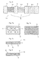
- Fig. 7a to 7c show various elements of an interior component 100 as they are assembled into the interior component 100.
- Fig. 7a is a die 70 imaged a fiber composite element.
- the die 70 of the fiber composite element includes a plurality of recesses 74, which are introduced in the form of through holes in the die.
- Fig. 7b shows the to the in Fig. 7a shown template 70, which has projections 76 on its surface, the recesses 74 in the die 70 in their arrangement and dimensioning Fig. 7a correspond.
- Fig. 7c shows such a fiber composite element 10, which results from the composite elements of the die 70 and male 72.
- the fiber composite element 10 is in the in Fig. 7c shown state already pressed to the interior component 100.
- the sectional view of the Fig. 7c clearly shows the projections 76 of the male part 72 and the recesses 74 of the die 70.
- the section, the Fig. 7c shows is in Fig. 7a as route AA indicated.
- Fig. 8 shows the interior component 100 Fig. 7c , which has the die 70 and the male part 72, in the same sectional view. Between the state of the interior component according to Fig. 7c and in Fig. 8 As shown in the state of the interior component 100, an additional structure was applied to the surface 80 of the interior component 100 during a final pressing step.
- the finish-structured surface 80 has a relief that can cause an additional optical effect.
- FIGS. 7a to 7c and 8 An embodiment of the interior component 100, as shown for example in the FIGS. 7a to 7c and 8 is shown, particularly well allows the creation of a masonry, tile, hole or shaft design.
- Shaft design can be further performed and improved by a sharp-nip treatment of the fiber composite element.
- Fig. 9a-9c shows in a sectional view another way of processing the fiber composite element.
- Fig. 9a shows a first fiber composite element 90 and a second fiber composite element 92.
- the contact surface between the first fiber composite element 90 and the second fiber composite element 92 is provided with a wave-shaped relief.
- the two fiber composite elements 90, 92 are in the in Fig. 9a shown state joined together and thus interconnected.
- Fig. 9b shows the first fiber composite element 90 and the second fiber composite element 92, wherein between the state of Fig. 9a and the state of Fig. 9b a step of sharpening has taken place.
- the second fiber composite element 92 has been partially removed in its thickness direction and thinned or completely removed according to the relief of the contact surface between the first fiber composite element 90 and the second fiber composite element 92.
- Fig. 9c shows the composite of the first fiber composite element 90 and the second fiber composite element 92, wherein the surface of the second fiber composite element is provided with an additional relief structure.
- Microperforations 94 ie small blind holes or through holes, are introduced into the first fiber composite element 90 in the area of the relief-like elevations from the rear, which can optionally be filled, for example, by a polymer or other materials. The microperforations allow targeted control of the surface incidence.
- the fiber composite element 10 made of the first fiber composite element 90 and the second fiber composite element 92 can be used for final compression, as shown in FIG Fig. 9c is pressed with a tool 96, which in turn can be made rigid or flexible and with or without a textured surface.
- FIG. 10 shows a fiber composite element 10 having embedded structures 102 and a sealing layer 104 that protects the visible surface of the fiber composite element 10 and the embedded structures 102.
- At least one soft haptic layer may be provided below the veneer layer, which allows a soft-feeling surface of the interior component. This enhances a high-quality impression of the interior component.
- Fig. 11 shows another possible embodiment of an interior component 110.
- the interior component 110 has various regions 112 to 118 with different structures and surface topographies. Again Fig. 11 As can be seen, the areas of different structure and surface topography can be combined almost arbitrarily, thus creating a wide variety of possible surface designs.
- Fig. 12 shows a further embodiment of an interior component 120.
- This figure shows a section of such an interior component 120 with a surface structuring 122, which was produced by deposits in the fiber composite element.
- the deposits 122 of the surface structuring give the impression of an artificial grain of the interior component and thus contribute to further increasing the artificial freedom of design of an interior component.
- the embodiments described above enable the manufacture of an interior component that exhibits a multiplicity of defined artificial surface designs.
- the so available interior component is easy to produce and gives the viewer a high-quality impression.
Landscapes
- Engineering & Computer Science (AREA)
- Chemical & Material Sciences (AREA)
- Composite Materials (AREA)
- Mechanical Engineering (AREA)
- Textile Engineering (AREA)
- Life Sciences & Earth Sciences (AREA)
- Manufacturing & Machinery (AREA)
- Wood Science & Technology (AREA)
- Forests & Forestry (AREA)
- Vehicle Interior And Exterior Ornaments, Soundproofing, And Insulation (AREA)
- Laminated Bodies (AREA)
Claims (7)
- Elément intérieur (100, 110, 120) pour un véhicule, comprenant:un côté visible, qui est en cours d'utilisation visuellement perceptible par un observateur;un élément composite en fibres (10) avec une surface, qui forme au moins une partie du côté visible, l'élément composite en fibres (10) étant au moins partiellement comprimé; etune couche de protection en plusieurs couches déposée au moins sur la surface visible de l'élément composite en fibres,caractérisé en ce que l'élément composite en fibres se compose d'une matrice avec des fibres de renforcement,dans lequel la couche de la couche de protection se trouvant en contact avec la surface de l'élément composite en fibres est formée d'un matériau correspondant au matériau de matrice.
- Elément intérieur (100, 110, 120) selon la revendication 1, dans lequel la couche de protection est un film (52) de préférence étanche au liquide avec plusieurs couches transparentes.
- Elément intérieur (100, 110, 120) selon la revendication 1 ou 2, dans lequel l'élément composite en fibres se compose d'une matrice avec des fibres naturelles-polypropylène.
- Elément intérieur (100, 110, 120) selon la revendication 3, dans lequel la couche de la couche de protection se trouvant en contact avec la surface de l'élément composite en fibres est formée en un matériau à base de polypropylène.
- Elément intérieur (100, 110, 120) selon l'une quelconque des revendications précédentes, dans lequel au moins une couche de la couche de protection est colorée.
- Elément intérieur (100, 110, 120) selon l'une quelconque des revendications précédentes, dans lequel la couche la plus extérieure de la couche de protection est stable aux UV et résistante aux éraflures.
- Procédé de production d'un élément intérieur (100, 110, 120) pour un véhicule selon l'une quelconque des revendications précédentes, comprenant les étapes suivantes:comprimer un élément composite en fibres (10), de telle manière que l'élément composite en fibres (10) présente ensuite une structure superficielle artificielle définie au moins sur un côté visible de l'élément intérieur, etdéposer une couche de protection en plusieurs couches (52, 104) sur l'élément composite en fibres (10).
Applications Claiming Priority (2)
| Application Number | Priority Date | Filing Date | Title |
|---|---|---|---|
| DE102010028247A DE102010028247A1 (de) | 2010-04-27 | 2010-04-27 | Interieurbauteil mit künstlicher Oberflächengestaltung und Verfahren zu dessen Herstellung |
| PCT/EP2011/056629 WO2011134983A2 (fr) | 2010-04-27 | 2011-04-27 | Élément intérieur à structure superficielle artificielle et procédé pour le produire |
Publications (2)
| Publication Number | Publication Date |
|---|---|
| EP2563570A2 EP2563570A2 (fr) | 2013-03-06 |
| EP2563570B1 true EP2563570B1 (fr) | 2015-01-21 |
Family
ID=44280789
Family Applications (1)
| Application Number | Title | Priority Date | Filing Date |
|---|---|---|---|
| EP11716902.9A Active EP2563570B1 (fr) | 2010-04-27 | 2011-04-27 | Élément intérieur à structure superficielle artificielle et procédé pour le produire |
Country Status (3)
| Country | Link |
|---|---|
| EP (1) | EP2563570B1 (fr) |
| DE (1) | DE102010028247A1 (fr) |
| WO (1) | WO2011134983A2 (fr) |
Cited By (2)
| Publication number | Priority date | Publication date | Assignee | Title |
|---|---|---|---|---|
| EP3613573A1 (fr) | 2018-08-23 | 2020-02-26 | Motherson Innovations Company Limited | Composant d'habillage destiné à habiller l'espace intérieur d'un moyen de transport de personnes ainsi que procédé de fabrication d'un tel composant d'habillage |
| EP4520527A1 (fr) * | 2023-09-05 | 2025-03-12 | Benecke-Kaliko AG | Composite multicouche |
Families Citing this family (10)
| Publication number | Priority date | Publication date | Assignee | Title |
|---|---|---|---|---|
| CN108790314A (zh) | 2011-08-05 | 2018-11-13 | 上海延锋金桥汽车饰件系统有限公司 | 具有基于植物的天然产物的内饰装配零部件 |
| DE102011115803B4 (de) | 2011-10-12 | 2018-04-26 | Oechsler Aktiengesellschaft | Halbzeug aus einem Verbund von Fasern in einer Kunststoffmatrix und Verfahren zum Gewinnen von Bauteilen aus derartigem Halbzeug |
| DE102012216727A1 (de) * | 2012-09-19 | 2014-05-28 | Bayerische Motoren Werke Aktiengesellschaft | Funktionsoptimiertes Faserverbundbauteil und Verfahren zu dessen Herstellung |
| DE102014004880A1 (de) | 2014-04-04 | 2015-10-08 | Lisa Dräxlmaier GmbH | Verfahren zur Herstellung eines Dekorelements |
| DE102014209400A1 (de) | 2014-05-19 | 2015-11-19 | Bayerische Motoren Werke Aktiengesellschaft | Formwerkzeug |
| DE102014114012B4 (de) * | 2014-09-26 | 2022-12-29 | Deutsches Zentrum für Luft- und Raumfahrt e.V. | Verfahren zur Herstellung eines Faserverbundbauteils |
| NL2017025B1 (nl) * | 2016-06-22 | 2018-01-04 | Apeldoorn Flexible Packaging B V | Werkwijze voor het afwerken van een zichtzijde van een interieurdeel van geperst vezelmateriaal en interieurdeel met zodanig afgewerkte zichtzijde |
| DE102018116292A1 (de) * | 2018-07-05 | 2020-01-09 | Dr. Ing. H.C. F. Porsche Aktiengesellschaft | Fahrzeugteil |
| DE102024119762A1 (de) | 2024-07-11 | 2026-01-15 | Smrc Automotive Holdings Netherlands B.V. | Verkleidungsplattenteil für einen Fahrzeuginnenraum |
| DE102024130235A1 (de) * | 2024-10-17 | 2026-04-23 | Joysonquin Automotive Systems Gmbh | Dekorteil für den Innenraum eines Fahrzeugs und Verfahren zu dessen Herstellung |
Citations (2)
| Publication number | Priority date | Publication date | Assignee | Title |
|---|---|---|---|---|
| DE10212961A1 (de) * | 2002-03-22 | 2003-10-02 | Inst Neue Mat Gemein Gmbh | Kunststofffolie mit Mehrschicht-Interferenzbeschichtung |
| DE102009049122A1 (de) * | 2009-10-12 | 2011-04-14 | Sihl Gmbh | Kratzfeste Polypropylenfolie |
Family Cites Families (12)
| Publication number | Priority date | Publication date | Assignee | Title |
|---|---|---|---|---|
| DE3825987C2 (de) * | 1988-07-27 | 1994-06-23 | Lignotock Gmbh | Formbare und verdichtungsfähige Fasermatte mit Treibmittelzusatz zum Herstellen von Formteilen |
| AU8811091A (en) * | 1990-12-21 | 1992-07-02 | Creative Industries Group, Inc. | Woven fibers in clear matrix finish for automotive interiors |
| DE4128927C2 (de) * | 1991-08-30 | 1996-07-25 | Lignotock Gmbh | Recycling von Formteilen aus bindemittelhaltigen Zellulose- oder Lignozellulosewerkstoffen |
| DE19540189A1 (de) * | 1995-10-29 | 1997-04-30 | Thomas Oschmann | Preßvorrichtung und -verfahren zur Herstellung von Formteilen aus Faserverbundwerkstoffen |
| JPH09226082A (ja) * | 1995-12-22 | 1997-09-02 | Toyoda Gosei Co Ltd | 化粧成形品及びその製造方法 |
| DE29713779U1 (de) * | 1997-08-02 | 1997-10-09 | SOMMER ALLIBERT-LIGNOTOCK GmbH, 76744 Wörth | Mehrschichtiges Formteil |
| DE19957850A1 (de) * | 1999-12-01 | 2001-06-07 | Draexlmaier Lisa Gmbh | Verfahren zum Beschichten eines Trägerteils mit einem Bezugmaterial und zugehörige Vorrichtung |
| DE10044760A1 (de) * | 2000-09-09 | 2002-04-04 | Findlay Ind Deutschland Gmbh | Mehrschaliges Innenverkleidungsteil |
| JP2002192665A (ja) * | 2000-12-27 | 2002-07-10 | Toyoda Iron Works Co Ltd | 透明シート貼合せ成形品 |
| DE10113273A1 (de) * | 2001-03-16 | 2002-09-19 | Basf Ag | Verbundformteile mit einer Folienbeschichtung und Verfahren zu deren Herstellung |
| DE10136125A1 (de) * | 2001-07-26 | 2003-02-13 | Basell Polyolefine Gmbh | Schichtverbundmaterial sowie Verfahren zur Herstellung des Schichtverbundmaterials |
| DE102006062345A1 (de) | 2006-12-22 | 2008-06-26 | Foliotec Gmbh | Dreidimensionales Dekorformteil |
-
2010
- 2010-04-27 DE DE102010028247A patent/DE102010028247A1/de not_active Withdrawn
-
2011
- 2011-04-27 WO PCT/EP2011/056629 patent/WO2011134983A2/fr not_active Ceased
- 2011-04-27 EP EP11716902.9A patent/EP2563570B1/fr active Active
Patent Citations (2)
| Publication number | Priority date | Publication date | Assignee | Title |
|---|---|---|---|---|
| DE10212961A1 (de) * | 2002-03-22 | 2003-10-02 | Inst Neue Mat Gemein Gmbh | Kunststofffolie mit Mehrschicht-Interferenzbeschichtung |
| DE102009049122A1 (de) * | 2009-10-12 | 2011-04-14 | Sihl Gmbh | Kratzfeste Polypropylenfolie |
Cited By (4)
| Publication number | Priority date | Publication date | Assignee | Title |
|---|---|---|---|---|
| EP3613573A1 (fr) | 2018-08-23 | 2020-02-26 | Motherson Innovations Company Limited | Composant d'habillage destiné à habiller l'espace intérieur d'un moyen de transport de personnes ainsi que procédé de fabrication d'un tel composant d'habillage |
| CN110857062A (zh) * | 2018-08-23 | 2020-03-03 | 玛泽森创新有限公司 | 用于遮盖人员运输工具的内部空间的挡板构件以及用于制造这样的挡板构件的方法 |
| CN110857062B (zh) * | 2018-08-23 | 2024-02-23 | 玛泽森创新有限公司 | 用于制造挡板构件的方法、人员运输工具以及挡板构件 |
| EP4520527A1 (fr) * | 2023-09-05 | 2025-03-12 | Benecke-Kaliko AG | Composite multicouche |
Also Published As
| Publication number | Publication date |
|---|---|
| DE102010028247A1 (de) | 2011-10-27 |
| WO2011134983A2 (fr) | 2011-11-03 |
| EP2563570A2 (fr) | 2013-03-06 |
| WO2011134983A3 (fr) | 2012-03-08 |
Similar Documents
| Publication | Publication Date | Title |
|---|---|---|
| EP2563570B1 (fr) | Élément intérieur à structure superficielle artificielle et procédé pour le produire | |
| EP2435247B1 (fr) | Methode pour produire un element decoratif en cuir et element decoratif de piece automobile en cuir | |
| EP2684745B1 (fr) | Pièce d'habillage intérieur et son procédé de fabrication | |
| EP2729289B1 (fr) | Piece moulee et son procede de fabrication | |
| DE102013013348A1 (de) | Fahrzeuginnenkomponenten mit dekorativer Naht | |
| EP3023308B1 (fr) | Partie de revetement interieur et son procede de fabrication | |
| EP2516213B1 (fr) | Procédé de fabrication de pièces d'habillage de véhicules automobiles | |
| EP2279915B1 (fr) | Composants d'équipement intérieur à plusieurs couleurs | |
| DE102015003448A1 (de) | Zierteil, Dekorteil und Verfahren zur Herstellung eines Zierteils | |
| EP3960440A1 (fr) | Feuille stratifiée renforcée par un tissu | |
| DE68926035T2 (de) | Methode, mehrschichtlaminate mit einer aussenschicht aus qualitätsholz oder pflanzenfasergewebe darzustellen, zum furnieren und zum gebrauch in der herstellung von genähten gegenständen, und die so erhaltenen produkte | |
| DE102013202095B4 (de) | Herstellung strukturierter Dekorschichten für Ausstattungsteile | |
| DE3233675C2 (de) | Verfahren zum Herstellen von an der Oberfläche kaschierten und Prägemuster aufweisenden Formteilen, vorzugsweise zur Innenverkleidung von Fahrgastzellen für Fahrzeuge aller Art | |
| AT506942B1 (de) | Verfahren zur herstellung eines innenverkleidungsteils | |
| DE102009000559B4 (de) | Verbundwerkstoffverbindungsbereich für die Innenverkleidung eines Kraftfahrzeugs | |
| DE102015109571A1 (de) | Fahrzeug-innenverkleidungskomponenten und zugehörige verfahren | |
| DE102018118426A1 (de) | Verfahren und system zur verwendung eines offenen spritzgiessverfahrens mit einem einzelwerkzeug für verkleidungskomponenten | |
| DE102016121736A1 (de) | Innenverkleidungsteil und Verfahren zu seiner Herstellung | |
| DE102010000633A1 (de) | Biegeschlaffes Flächengebilde sowie Verfahren zur Herstellung | |
| DE102008062200A1 (de) | Trägerfreies Dekor | |
| DE102024203946A1 (de) | Verfahren zur Herstellung eines mit einer Prägung und/ oder Applikation in bzw. auf einer Oberfläche versehenen Verkleidungsteils eines Kraftfahrzeugs und Kraftfahrzeug | |
| DE102012020484B4 (de) | Verfahren zur Herstellung eines wenigstens zwei Schichten aufweisenden Bauteils und Bauteil | |
| DE102008016078A1 (de) | Verfahren zum Herstellen eines mindestens einen Nahtverlauf aufweisenden Flächenbauteils | |
| DE202007016726U1 (de) | Dekorbauteil | |
| DE202025107965U1 (de) | Flexibles Mehrschichtmaterial, Fahrzeuginnenraumkomponente und Rollabdeckung mit einem solchen |
Legal Events
| Date | Code | Title | Description |
|---|---|---|---|
| PUAI | Public reference made under article 153(3) epc to a published international application that has entered the european phase |
Free format text: ORIGINAL CODE: 0009012 |
|
| 17P | Request for examination filed |
Effective date: 20121105 |
|
| AK | Designated contracting states |
Kind code of ref document: A2 Designated state(s): AL AT BE BG CH CY CZ DE DK EE ES FI FR GB GR HR HU IE IS IT LI LT LU LV MC MK MT NL NO PL PT RO RS SE SI SK SM TR |
|
| DAX | Request for extension of the european patent (deleted) | ||
| 17Q | First examination report despatched |
Effective date: 20131108 |
|
| GRAP | Despatch of communication of intention to grant a patent |
Free format text: ORIGINAL CODE: EPIDOSNIGR1 |
|
| RIC1 | Information provided on ipc code assigned before grant |
Ipc: B29C 70/08 20060101AFI20140811BHEP Ipc: B29K 711/14 20060101ALN20140811BHEP Ipc: B29K 311/10 20060101ALN20140811BHEP Ipc: B29L 31/30 20060101ALN20140811BHEP Ipc: B29C 70/46 20060101ALI20140811BHEP Ipc: B32B 27/06 20060101ALI20140811BHEP |
|
| INTG | Intention to grant announced |
Effective date: 20140912 |
|
| GRAS | Grant fee paid |
Free format text: ORIGINAL CODE: EPIDOSNIGR3 |
|
| GRAA | (expected) grant |
Free format text: ORIGINAL CODE: 0009210 |
|
| AK | Designated contracting states |
Kind code of ref document: B1 Designated state(s): AL AT BE BG CH CY CZ DE DK EE ES FI FR GB GR HR HU IE IS IT LI LT LU LV MC MK MT NL NO PL PT RO RS SE SI SK SM TR |
|
| REG | Reference to a national code |
Ref country code: GB Ref legal event code: FG4D Free format text: NOT ENGLISH |
|
| REG | Reference to a national code |
Ref country code: CH Ref legal event code: EP |
|
| REG | Reference to a national code |
Ref country code: IE Ref legal event code: FG4D Free format text: LANGUAGE OF EP DOCUMENT: GERMAN |
|
| REG | Reference to a national code |
Ref country code: DE Ref legal event code: R096 Ref document number: 502011005718 Country of ref document: DE Effective date: 20150226 |
|
| REG | Reference to a national code |
Ref country code: AT Ref legal event code: REF Ref document number: 708961 Country of ref document: AT Kind code of ref document: T Effective date: 20150315 |
|
| REG | Reference to a national code |
Ref country code: NL Ref legal event code: VDEP Effective date: 20150121 |
|
| REG | Reference to a national code |
Ref country code: LT Ref legal event code: MG4D |
|
| PG25 | Lapsed in a contracting state [announced via postgrant information from national office to epo] |
Ref country code: ES Free format text: LAPSE BECAUSE OF FAILURE TO SUBMIT A TRANSLATION OF THE DESCRIPTION OR TO PAY THE FEE WITHIN THE PRESCRIBED TIME-LIMIT Effective date: 20150121 Ref country code: HR Free format text: LAPSE BECAUSE OF FAILURE TO SUBMIT A TRANSLATION OF THE DESCRIPTION OR TO PAY THE FEE WITHIN THE PRESCRIBED TIME-LIMIT Effective date: 20150121 Ref country code: NO Free format text: LAPSE BECAUSE OF FAILURE TO SUBMIT A TRANSLATION OF THE DESCRIPTION OR TO PAY THE FEE WITHIN THE PRESCRIBED TIME-LIMIT Effective date: 20150421 Ref country code: SE Free format text: LAPSE BECAUSE OF FAILURE TO SUBMIT A TRANSLATION OF THE DESCRIPTION OR TO PAY THE FEE WITHIN THE PRESCRIBED TIME-LIMIT Effective date: 20150121 Ref country code: FI Free format text: LAPSE BECAUSE OF FAILURE TO SUBMIT A TRANSLATION OF THE DESCRIPTION OR TO PAY THE FEE WITHIN THE PRESCRIBED TIME-LIMIT Effective date: 20150121 Ref country code: BG Free format text: LAPSE BECAUSE OF FAILURE TO SUBMIT A TRANSLATION OF THE DESCRIPTION OR TO PAY THE FEE WITHIN THE PRESCRIBED TIME-LIMIT Effective date: 20150421 Ref country code: LT Free format text: LAPSE BECAUSE OF FAILURE TO SUBMIT A TRANSLATION OF THE DESCRIPTION OR TO PAY THE FEE WITHIN THE PRESCRIBED TIME-LIMIT Effective date: 20150121 |
|
| PG25 | Lapsed in a contracting state [announced via postgrant information from national office to epo] |
Ref country code: IS Free format text: LAPSE BECAUSE OF FAILURE TO SUBMIT A TRANSLATION OF THE DESCRIPTION OR TO PAY THE FEE WITHIN THE PRESCRIBED TIME-LIMIT Effective date: 20150521 Ref country code: LV Free format text: LAPSE BECAUSE OF FAILURE TO SUBMIT A TRANSLATION OF THE DESCRIPTION OR TO PAY THE FEE WITHIN THE PRESCRIBED TIME-LIMIT Effective date: 20150121 Ref country code: PL Free format text: LAPSE BECAUSE OF FAILURE TO SUBMIT A TRANSLATION OF THE DESCRIPTION OR TO PAY THE FEE WITHIN THE PRESCRIBED TIME-LIMIT Effective date: 20150121 Ref country code: NL Free format text: LAPSE BECAUSE OF FAILURE TO SUBMIT A TRANSLATION OF THE DESCRIPTION OR TO PAY THE FEE WITHIN THE PRESCRIBED TIME-LIMIT Effective date: 20150121 Ref country code: GR Free format text: LAPSE BECAUSE OF FAILURE TO SUBMIT A TRANSLATION OF THE DESCRIPTION OR TO PAY THE FEE WITHIN THE PRESCRIBED TIME-LIMIT Effective date: 20150422 Ref country code: RS Free format text: LAPSE BECAUSE OF FAILURE TO SUBMIT A TRANSLATION OF THE DESCRIPTION OR TO PAY THE FEE WITHIN THE PRESCRIBED TIME-LIMIT Effective date: 20150121 |
|
| REG | Reference to a national code |
Ref country code: DE Ref legal event code: R097 Ref document number: 502011005718 Country of ref document: DE |
|
| PG25 | Lapsed in a contracting state [announced via postgrant information from national office to epo] |
Ref country code: RO Free format text: LAPSE BECAUSE OF FAILURE TO SUBMIT A TRANSLATION OF THE DESCRIPTION OR TO PAY THE FEE WITHIN THE PRESCRIBED TIME-LIMIT Effective date: 20150121 Ref country code: EE Free format text: LAPSE BECAUSE OF FAILURE TO SUBMIT A TRANSLATION OF THE DESCRIPTION OR TO PAY THE FEE WITHIN THE PRESCRIBED TIME-LIMIT Effective date: 20150121 Ref country code: CZ Free format text: LAPSE BECAUSE OF FAILURE TO SUBMIT A TRANSLATION OF THE DESCRIPTION OR TO PAY THE FEE WITHIN THE PRESCRIBED TIME-LIMIT Effective date: 20150121 Ref country code: SK Free format text: LAPSE BECAUSE OF FAILURE TO SUBMIT A TRANSLATION OF THE DESCRIPTION OR TO PAY THE FEE WITHIN THE PRESCRIBED TIME-LIMIT Effective date: 20150121 Ref country code: DK Free format text: LAPSE BECAUSE OF FAILURE TO SUBMIT A TRANSLATION OF THE DESCRIPTION OR TO PAY THE FEE WITHIN THE PRESCRIBED TIME-LIMIT Effective date: 20150121 |
|
| PLBE | No opposition filed within time limit |
Free format text: ORIGINAL CODE: 0009261 |
|
| STAA | Information on the status of an ep patent application or granted ep patent |
Free format text: STATUS: NO OPPOSITION FILED WITHIN TIME LIMIT |
|
| PG25 | Lapsed in a contracting state [announced via postgrant information from national office to epo] |
Ref country code: MC Free format text: LAPSE BECAUSE OF FAILURE TO SUBMIT A TRANSLATION OF THE DESCRIPTION OR TO PAY THE FEE WITHIN THE PRESCRIBED TIME-LIMIT Effective date: 20150121 Ref country code: LU Free format text: LAPSE BECAUSE OF FAILURE TO SUBMIT A TRANSLATION OF THE DESCRIPTION OR TO PAY THE FEE WITHIN THE PRESCRIBED TIME-LIMIT Effective date: 20150427 |
|
| REG | Reference to a national code |
Ref country code: CH Ref legal event code: PL |
|
| 26N | No opposition filed |
Effective date: 20151022 |
|
| REG | Reference to a national code |
Ref country code: IE Ref legal event code: MM4A |
|
| PG25 | Lapsed in a contracting state [announced via postgrant information from national office to epo] |
Ref country code: LI Free format text: LAPSE BECAUSE OF NON-PAYMENT OF DUE FEES Effective date: 20150430 Ref country code: CH Free format text: LAPSE BECAUSE OF NON-PAYMENT OF DUE FEES Effective date: 20150430 |
|
| PG25 | Lapsed in a contracting state [announced via postgrant information from national office to epo] |
Ref country code: SI Free format text: LAPSE BECAUSE OF FAILURE TO SUBMIT A TRANSLATION OF THE DESCRIPTION OR TO PAY THE FEE WITHIN THE PRESCRIBED TIME-LIMIT Effective date: 20150121 |
|
| REG | Reference to a national code |
Ref country code: FR Ref legal event code: PLFP Year of fee payment: 6 |
|
| PG25 | Lapsed in a contracting state [announced via postgrant information from national office to epo] |
Ref country code: IE Free format text: LAPSE BECAUSE OF NON-PAYMENT OF DUE FEES Effective date: 20150427 |
|
| PG25 | Lapsed in a contracting state [announced via postgrant information from national office to epo] |
Ref country code: MT Free format text: LAPSE BECAUSE OF FAILURE TO SUBMIT A TRANSLATION OF THE DESCRIPTION OR TO PAY THE FEE WITHIN THE PRESCRIBED TIME-LIMIT Effective date: 20150121 |
|
| REG | Reference to a national code |
Ref country code: FR Ref legal event code: PLFP Year of fee payment: 7 |
|
| PG25 | Lapsed in a contracting state [announced via postgrant information from national office to epo] |
Ref country code: SM Free format text: LAPSE BECAUSE OF FAILURE TO SUBMIT A TRANSLATION OF THE DESCRIPTION OR TO PAY THE FEE WITHIN THE PRESCRIBED TIME-LIMIT Effective date: 20150121 Ref country code: HU Free format text: LAPSE BECAUSE OF FAILURE TO SUBMIT A TRANSLATION OF THE DESCRIPTION OR TO PAY THE FEE WITHIN THE PRESCRIBED TIME-LIMIT; INVALID AB INITIO Effective date: 20110427 |
|
| REG | Reference to a national code |
Ref country code: AT Ref legal event code: MM01 Ref document number: 708961 Country of ref document: AT Kind code of ref document: T Effective date: 20160427 |
|
| PG25 | Lapsed in a contracting state [announced via postgrant information from national office to epo] |
Ref country code: CY Free format text: LAPSE BECAUSE OF FAILURE TO SUBMIT A TRANSLATION OF THE DESCRIPTION OR TO PAY THE FEE WITHIN THE PRESCRIBED TIME-LIMIT Effective date: 20150121 |
|
| PG25 | Lapsed in a contracting state [announced via postgrant information from national office to epo] |
Ref country code: BE Free format text: LAPSE BECAUSE OF NON-PAYMENT OF DUE FEES Effective date: 20150430 Ref country code: PT Free format text: LAPSE BECAUSE OF FAILURE TO SUBMIT A TRANSLATION OF THE DESCRIPTION OR TO PAY THE FEE WITHIN THE PRESCRIBED TIME-LIMIT Effective date: 20150521 |
|
| PG25 | Lapsed in a contracting state [announced via postgrant information from national office to epo] |
Ref country code: AT Free format text: LAPSE BECAUSE OF NON-PAYMENT OF DUE FEES Effective date: 20160427 Ref country code: TR Free format text: LAPSE BECAUSE OF FAILURE TO SUBMIT A TRANSLATION OF THE DESCRIPTION OR TO PAY THE FEE WITHIN THE PRESCRIBED TIME-LIMIT Effective date: 20150121 |
|
| REG | Reference to a national code |
Ref country code: FR Ref legal event code: PLFP Year of fee payment: 8 |
|
| PG25 | Lapsed in a contracting state [announced via postgrant information from national office to epo] |
Ref country code: MK Free format text: LAPSE BECAUSE OF FAILURE TO SUBMIT A TRANSLATION OF THE DESCRIPTION OR TO PAY THE FEE WITHIN THE PRESCRIBED TIME-LIMIT Effective date: 20150121 |
|
| PG25 | Lapsed in a contracting state [announced via postgrant information from national office to epo] |
Ref country code: AL Free format text: LAPSE BECAUSE OF FAILURE TO SUBMIT A TRANSLATION OF THE DESCRIPTION OR TO PAY THE FEE WITHIN THE PRESCRIBED TIME-LIMIT Effective date: 20150121 |
|
| PGFP | Annual fee paid to national office [announced via postgrant information from national office to epo] |
Ref country code: IT Payment date: 20200312 Year of fee payment: 10 |
|
| PG25 | Lapsed in a contracting state [announced via postgrant information from national office to epo] |
Ref country code: IT Free format text: LAPSE BECAUSE OF NON-PAYMENT OF DUE FEES Effective date: 20200427 |
|
| P01 | Opt-out of the competence of the unified patent court (upc) registered |
Effective date: 20231017 |
|
| PGFP | Annual fee paid to national office [announced via postgrant information from national office to epo] |
Ref country code: FR Payment date: 20250310 Year of fee payment: 15 |
|
| PGFP | Annual fee paid to national office [announced via postgrant information from national office to epo] |
Ref country code: GB Payment date: 20250306 Year of fee payment: 15 |
|
| PGFP | Annual fee paid to national office [announced via postgrant information from national office to epo] |
Ref country code: DE Payment date: 20250430 Year of fee payment: 15 |
|
| PG25 | Lapsed in a contracting state [announced via postgrant information from national office to epo] |
Ref country code: IT Free format text: LAPSE BECAUSE OF NON-PAYMENT OF DUE FEES Effective date: 20210427 |