EP2565329A2 - Gabarit de pieux pour l'installation de fondations en acier de type jacket au fond de la mer - Google Patents
Gabarit de pieux pour l'installation de fondations en acier de type jacket au fond de la mer Download PDFInfo
- Publication number
- EP2565329A2 EP2565329A2 EP12005948A EP12005948A EP2565329A2 EP 2565329 A2 EP2565329 A2 EP 2565329A2 EP 12005948 A EP12005948 A EP 12005948A EP 12005948 A EP12005948 A EP 12005948A EP 2565329 A2 EP2565329 A2 EP 2565329A2
- Authority
- EP
- European Patent Office
- Prior art keywords
- guide tube
- guide
- ram
- template according
- tubes
- Prior art date
- Legal status (The legal status is an assumption and is not a legal conclusion. Google has not performed a legal analysis and makes no representation as to the accuracy of the status listed.)
- Withdrawn
Links
- 229910000831 Steel Inorganic materials 0.000 title claims description 18
- 239000010959 steel Substances 0.000 title claims description 18
- 238000009434 installation Methods 0.000 title claims description 5
- 239000000725 suspension Substances 0.000 claims description 10
- XLYOFNOQVPJJNP-UHFFFAOYSA-N water Substances O XLYOFNOQVPJJNP-UHFFFAOYSA-N 0.000 claims description 8
- 239000011358 absorbing material Substances 0.000 claims description 4
- 238000009413 insulation Methods 0.000 claims description 4
- 238000005553 drilling Methods 0.000 abstract description 4
- 238000000034 method Methods 0.000 abstract description 2
- 238000006073 displacement reaction Methods 0.000 abstract 1
- 238000003780 insertion Methods 0.000 description 2
- 230000037431 insertion Effects 0.000 description 2
- 239000013535 sea water Substances 0.000 description 2
- 239000000969 carrier Substances 0.000 description 1
- 238000010276 construction Methods 0.000 description 1
- 230000000694 effects Effects 0.000 description 1
- 230000007613 environmental effect Effects 0.000 description 1
- 230000002349 favourable effect Effects 0.000 description 1
- 230000005484 gravity Effects 0.000 description 1
- 239000011810 insulating material Substances 0.000 description 1
- 230000035939 shock Effects 0.000 description 1
- 238000003756 stirring Methods 0.000 description 1
Images




Classifications
-
- E—FIXED CONSTRUCTIONS
- E02—HYDRAULIC ENGINEERING; FOUNDATIONS; SOIL SHIFTING
- E02D—FOUNDATIONS; EXCAVATIONS; EMBANKMENTS; UNDERGROUND OR UNDERWATER STRUCTURES
- E02D13/00—Accessories for placing or removing piles or bulkheads, e.g. noise attenuating chambers
- E02D13/04—Guide devices; Guide frames
Definitions
- the invention relates to a Rammschablone said in the preamble of claim 1 genus.
- a method of installing a jacket boot wherein a ram template comprising a plurality of guide tubes is placed on the seabed in the desired position and oriented horizontally. Then, with the help of a crane, the piles are lowered into the water by a ship for delivery to the guide tubes. Since the upper ends of the guide tubes are far below the water level, the exact alignment of the piles relative to the guide tubes requires a great deal of technical effort and is therefore very difficult and therefore time-consuming, especially in rough seas because of the relative movement of the crane relative to the fixed on the seabed Rammschablone.
- the invention has for its object to provide a Rammschablone, with the settling on the seabed is simplified and the noise emission is significantly reduced when driving in the piles.
- the template in a preferred embodiment comprises at least three guide tubes, which are interconnected by means of cross members and stiffening struts such that the template forms a dimensionally stable device with a base of a uniform polygon.
- a guide tube piece is arranged, wherein the guide tube pieces are interconnected by means of upper cross member, and that a lifting device is provided, by means of which the guide tube pieces can be raised relative to the guide tubes.
- the guide tubes have a length which is less than the water depth at the installation site of the steel jacket foundation and the guide tube pieces above the sea level are liftable. This has the advantage that the attack area in the shaft is minimal and therefore only small forces act on the Rammschablone. In addition, the guide tube pieces protrude from the water, whereby the threading of the pounding hammer is facilitated.
- the lifting device comprises, for example, at least one column arrangement with two telescopically extendable tubes, each column arrangement being connected to the guide tubes by means of connecting struts.
- the lifting device may comprise at least one lattice mast with two longitudinally displaceable lattice mast sections, wherein the lattice mast is connected by means of at least one strut arrangement with the guide tubes.
- Such lifting devices are provided with a locking element by which the extended position is maintained until the piles are rammed.
- a curtain is preferably provided, which surrounds the dimensionally stable device and thus all the guide tubes together.
- a curtain has a sound-reducing effect on all guide tubes of the driving template.
- the curtain is mounted so that it adapts to the retracted or extended position of the lifting device and thus the height of the ram template. It is advantageous that an upper end of the curtain is attached to the guide tube pieces and a lower end of the curtain is arranged on the feet.
- the guide tube is double-walled, ie it consists of at least two concentric steel tubes, and a cavity formed between the steel tubes is filled with a sound-absorbing material.
- This has the advantage that the noise emission when driving in the piles is significantly reduced, so that the environmental protection is taken into account to a considerable extent.
- two guide elements are provided in each guide tube, in which the piles are guided, wherein the guide elements are arranged relative to the length of the guide tube in a large axial distance from each other.
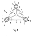
- a ram template 1 which serves for the installation of three-legged steel jacket foundations.
- the ram template 1 comprises three guide tubes 2, in each of which piles 3 are located centrally. Between the guide tubes 2 cross member 4 are arranged, which are fixed to the outer periphery of the respective guide tube 2. In Fig. 1 the cross member 4 form an equilateral triangle, at the corners of the guide tubes 2 are arranged.
- the ram template 1 comprises a suspension device 5, which consists of three from each guide tube 2 to the center of the triangle extending beams 6 and a surface center at the attached cylinder 7, which may be formed for example from a piece of pipe, and for connecting to a lifting device, for example a crane.
- a hydraulically actuated locking or clamping device which hangs on a crane cable, can clamp the cylinder 7 and in this way the ram template 1 can be raised or lowered.
- Out Fig. 1 is also apparent that the guide tubes 2 are double-walled, wherein the cavity formed between the two walls is filled with a sound-absorbing material 8.
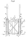
- the Fig. 2 shows a side view of the Rammschablone 1, wherein the two front guide tubes 2 and 3 piles are shown in longitudinal section.
- the piles 3 are prefabricated steel tubes to length, the length of which is slightly larger than that of the guide tubes 2.
- Fig. 2 it can be seen that, in addition to an upper and lower cross member 4, there are also diagonal bracing struts 9 which are fastened to the guide tubes 2 and / or the cross members 4. In this way, a great mechanical strength and rigidity of the ram template 1 is achieved, whereby deformation is avoided.
- the suspension device 5 is arranged, wherein from Fig. 2 it can be seen that the central axis of the cylinder 7 held by the supports 6 is vertically aligned.
- the existing steel piles 3 which are arranged by means of guide elements 10 in the interior of the guide tubes 2 accurately. These guide elements 10 are provided with respect to the length of the guide tube 2 in a large axial distance from each other.
- the piles 3 exit and penetrate into the seabed 11.
- clamping devices 12 are provided which serve for clamping the tubes 3 and hold them during the lowering and settling of the ram template 1 on the seabed 11.
- the upper ends of the guide tubes 2 protrude significantly above the sea level 13, so that the clamping devices 12 are above the sea level 13.
- the guide tubes 2 are designed as double-walled tubes, wherein the cavity between the tube walls is filled with a sound-absorbing material 8.
- the length of the guide tubes 2 to above the sea level 13 leads, compared to shorter guide tubes, to a higher accuracy of the direction of the piles introduced into the ground.
- the guide elements 10 may be self-threading, d. H. they open upwards conically like a funnel, whereby a pile 3 is automatically guided to the center and slides into the guide element 10.
- feet 14 are arranged, which support the Rammschablone 1 on the seabed 11.
- the feet 14 may be hydraulically or mechanically adjustable to level the Rammschablone 1 accordingly.
- the leveling of the ram template 1 can be done automatically or manually.
- the examination of the positional accuracy is carried out by means of suitable measuring equipment on the Rammschablone. 1
- pile extensions 15 whose diameters correspond exactly to the piles 3 and at the lower end have a pin 16 which is inserted into the upper end of the piles 3.
- the pile extension 15 also serves as a Rammeapter for the ram 17, which is formed for example as a hydraulically driven ram 17, which acts on the Rameter adapter 15. How out Fig. 2 it can be seen, the ram 17 is far above the Sea level 13 or the "splash zone", so that it is not exposed to seawater.
- a section of a transport ship 18 is shown with a crane 19 arranged thereon.
- the transport ship 18 has a working deck 18 ', on which the ramming template 1 and the piles 3 are transported to the intended position in the offshore area.
- a boom 20 of the crane 19 About a boom 20 of the crane 19, a crane cable 21 is guided at the end of a locking or clamping device 22 is attached.
- This device 22 is preferably hydraulically actuated and suitable to clamp the cylinder 7 of the suspension device 5 in order to maneuver the ramming template 1.
- the representation in Fig. 3 shows the upper part of the Rammschablone 1 with the carrier 6 comprehensive suspension device 5 and the outstanding over the sea level 13 guide tubes 2 and the piles therein 3 and this clamping fixtures 12 and the upper cross member 4 and the stiffening struts. 9
- the Rammschablone 1 is raised with the located in the guide tubes 2 piles 3 of the working platform 18 'and pivoted to the position which is provided for lowering the Rammschablone 1 on the seabed 11. Then the Rammschablone 1 is lowered into the water until the feet 14 reach the seabed 11 and the Rammschablone 1 is on the seabed.
- the device 22 can now be released from the cylinder 7 and pulled up by the crane cable 21.
- the leveling of the Rammschablone 1 by means of the adjustable feet 14 so that exactly the position of the Rammschablone 1 is set, which is required for the ramming of the piles 3 to form the planned steel jacket foundation.
- the clamping devices 12 are released from the piles 3, so that the piles 3 in the guide tubes 2 exclusively with the guide elements 10 have contact.
- the pile extensions 15 are placed on the piles, wherein the pin 16 is inserted into the pile 3 for centering.
- the ram 17, which is connected to the crane rope 21, positioned over the pile extension 15 and placed on this, as shown in Fig. 2 is shown on the left.
- the ram 17 can be put into operation, the pile extension 15 acts as a Rammadapter, whereby the shocks of the ram 17 are transferred to the pile 3 and this is driven into the seabed 11.
- the equipped with the sound-insulating material 8 double-walled guide tubes 2 absorb the sound waves generated by ramming, so that the reaching into the sea water noise emission is significantly reduced.
- the remaining piles are rammed. This is how the three-legged steel jacket foundations are made.
- the ram 17 and the pile extensions 15 must have a guide.
- the ramming template can be equipped with buoyant bodies which are flooded or removed after settling and before ramming.
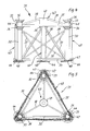
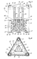
- Fig. 4 is shown a side view of a ram template 31 for a three-legged steel jacket foundation.
- the ram template 31 comprises three guide tubes 32, which according to Fig. 5 arranged in the form of an equilateral triangle.
- the guide tubes 32 are connected to each other via lower cross members 34 and stiffening struts 39. How out Fig. 4 can be seen, 32 short guide tube pieces 33 are arranged above the guide tubes, which are connected to each other by means of upper cross member 35 and with these also form the triangular shape as the guide tubes 32, which is apparent from the illustration in Fig. 5 results.
- the guide tubes 32 and guide tube pieces 33 are each provided at their upper ends with an upwardly opening feed hopper 36.
- a telescopic one Column assembly 40 is provided, which are connected via connecting struts 37 with the upper and lower ends of the guide tubes 32.
- the guide tubes 32, lower cross member 34, the column assembly 40 and connecting struts 37 and stiffening struts 39 together form a dimensionally stable device.
- Fig. 4 how out Fig. 4 can be seen, 32 leveling feet 44 are arranged at the lower ends of the guide tubes, wherein the leveling can be done hydraulically or mechanically.
- About the feet 44 is according to Fig. 4 at the lower end of each guide tube 32 a clamping or clamping device 48, which hold the inserted into the guide tubes 32 piles and protect against slipping out.
- the clamping or tensioning device 48 is mechanically or hydraulically actuated and is controlled by the staff on the transport ship. Only after the complete settling and leveling of the ram template 31, the piles are released by releasing the clamping device 48.
- the ram template 31 is according to Fig. 5 completely surrounded on its lateral surface by a curtain 45, which has sound-reducing properties.
- the upper end of the curtain 45 is according to Fig. 4 attached to outwardly projecting holders 46, which are arranged on the guide tube pieces 33. Of the holders 46, the curtain 45 hangs down with the lower end attached to the feet 44.
- the curtain 45 hangs down with the lower end attached to the feet 44.
- the in Fig. 4 As shown in retracted position of the telescopic column assembly 40 is a part of the curtain 45 in folds on the feet 44 on. In the edge region of the feet walls 47 are attached, which hold the folded layers of the curtain 45 at the corners of the Rammschablone 31.
- the telescopic column assembly 40 includes an outer tube 41 and an out Fig. 6 apparent inner tube 42, the upper end with a suspension device 43 (see. FIGS. 4 and 5 ) is connected, which has a cylinder 49 as a connecting means with a crane and by means of carriers 38 which carries the guide tube pieces 33 and upper cross members 35 formed device.
- a suspension device 43 see. FIGS. 4 and 5
- a cylinder 49 as a connecting means with a crane and by means of carriers 38 which carries the guide tube pieces 33 and upper cross members 35 formed device.
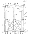
- Fig. 6 is shown, is in the extended state of the telescopic column assembly 40, the inner tube 42 in its highest position, thereby lifting the suspension device 43 with the cylinder 49, supports 38, the guide tube pieces 33 and upper Cross member 35 above the sea level 13.
- With the lifting of the guide tube pieces 33 and the holders 46 and the curtain 45 is also pulled up, so that its lower part is no longer in folds, but smooth surrounds the Rammschablone, as in Fig
- the Fig. 7 shows the piling 50 equipped with ram template 31.
- This insertion of the piles 50 in the guide tubes 32 and guide tube pieces 33 takes place on board the transport ship.
- the feed hoppers 36 facilitate the stirring of the piles 50 due to the self-centering.
- the piles 50 introduced to the lower end of the guide tubes 32 are then fixed by means of the clamping device 48.
- the reference numerals in Fig. 7 for equal parts with those of Fig. 4 match.
- the equipped with piles 50 Rammschablone 31 is then connected to a crane rope as well as this Fig. 3 is described.
- the cylinder 49 of the suspension device 43 which cooperates with a arranged on the crane cable connection device.
- the suspension device 43 By raising the crane rope, the suspension device 43 is raised with the straps 38, the guide tube pieces 33 and the upper cross member 35 attached to it until the maximum extension height of the inner tube 43 is reached, as the Fig. 8 shows.
- the inner tube 42 In order to maintain this extended position of the telescopic column assembly 40, the inner tube 42 is fixed to the outer tube. In this position, the lower part of the sound-reducing curtain 45 is pulled up.
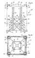
- FIGS. 9 and 10 show a ram template 51 with three guide tubes 32 in a triangular arrangement.
- the ram template 51 three vertical lattice masts 52, each consisting of two longitudinally mutually displaceable lattice boom sections 53 and 54.
- the lattice masts 52 are also arranged in the shape of an equilateral triangle, as is apparent from Fig. 10 is apparent.
- a first strut assembly 55 and for connection to the guide tubes 32 a second strut assembly 56 is provided for mechanically rigid connection of the lattice masts 52 with each other.
- a second strut assembly 56 is provided for mechanically rigid connection of the lattice masts 52 with each other.
- a first strut assembly 55 and for connection to the guide tubes 32 a second strut assembly 56 is provided.
- FIGS. 9 and 10 the reference numerals for like parts with those of FIGS. 4 to 6 match.
- a ram template 61 which comprises four guide tubes 32, whose arrangement includes a square base.
- the curtain 45 in this case surrounds the square formed by the guide tubes 32.
- the structure of the ram template 61 is similar to that according to FIGS. 4 to 6 , so that the same reference numerals match for the same components.
- FIGS. 13 and 14 show an alternative embodiment of the ram template 61, in which instead of the centric column assembly with telescopically extendable tubes an arrangement for raising the guide tube pieces 33 by means of lattice masts 52 analogous to the design of FIGS. 9 and 10 is provided, taking off Fig. 14 it can be seen that the lattice masts 52 form a square.
- the reference numerals for the same parts agree with the FIGS. 9 and 10 match.
- the overall height of the Rammschablonen 31, 51, 61 in the retracted state, as in Fig. 4 is shown, for example, 25 m to 30 m, preferably about 28 m.
- the total height of the ram template 31, 51, 61st about 45 to 55 m, preferably about 50 m.
- Rammschablonen with such dimensions are particularly suitable for driving piles in the offshore area with a water depth of 40 m to 45 m.
Landscapes
- Engineering & Computer Science (AREA)
- Life Sciences & Earth Sciences (AREA)
- General Life Sciences & Earth Sciences (AREA)
- Mining & Mineral Resources (AREA)
- Paleontology (AREA)
- Civil Engineering (AREA)
- General Engineering & Computer Science (AREA)
- Structural Engineering (AREA)
- Placing Or Removing Of Piles Or Sheet Piles, Or Accessories Thereof (AREA)
- Earth Drilling (AREA)
Applications Claiming Priority (1)
| Application Number | Priority Date | Filing Date | Title |
|---|---|---|---|
| DE201110112026 DE102011112026A1 (de) | 2011-08-31 | 2011-08-31 | Verfahren zum Installieren einer Stahl-Jacket-Gründung auf einem Meeresboden mittels einer Ramm-, Bohr- oder Schraubschablone und Schraub- oder Rammschablone für die Installation von Stahl-Jacket-Gründungen |
Publications (2)
| Publication Number | Publication Date |
|---|---|
| EP2565329A2 true EP2565329A2 (fr) | 2013-03-06 |
| EP2565329A3 EP2565329A3 (fr) | 2013-05-29 |
Family
ID=46785207
Family Applications (1)
| Application Number | Title | Priority Date | Filing Date |
|---|---|---|---|
| EP12005948.0A Withdrawn EP2565329A3 (fr) | 2011-08-31 | 2012-08-18 | Gabarit de pieux pour l'installation de fondations en acier de type jacket au fond de la mer |
Country Status (2)
| Country | Link |
|---|---|
| EP (1) | EP2565329A3 (fr) |
| DE (1) | DE102011112026A1 (fr) |
Cited By (3)
| Publication number | Priority date | Publication date | Assignee | Title |
|---|---|---|---|---|
| CN109056781A (zh) * | 2018-09-30 | 2018-12-21 | 中铁六局集团广州工程有限公司 | 一种水上塔吊基础和水中塔吊 |
| CN109594562A (zh) * | 2018-12-17 | 2019-04-09 | 闵瑞 | 一种轻便下沉式桥梁水上钻孔灌注桩钢护筒定位装置 |
| CN115125906A (zh) * | 2022-07-11 | 2022-09-30 | 中交第一航务工程局有限公司 | 导管架结构的码头及组合码头 |
Families Citing this family (2)
| Publication number | Priority date | Publication date | Assignee | Title |
|---|---|---|---|---|
| CN105421478B (zh) * | 2015-10-30 | 2017-05-31 | 北京思创佳德桩工机械制造有限公司 | 一种组合式塔吊塔基及其施工方法 |
| CN115262618B (zh) * | 2022-09-21 | 2023-09-01 | 南通市海洋水建工程有限公司 | 一种升压站钢结构基础施工配套工装及其方法 |
Citations (1)
| Publication number | Priority date | Publication date | Assignee | Title |
|---|---|---|---|---|
| EP2309063A1 (fr) | 2009-10-01 | 2011-04-13 | Aker Jacket Technology AS | Appareil, système et procédé d'extension de piliers au fond de la mer |
Family Cites Families (4)
| Publication number | Priority date | Publication date | Assignee | Title |
|---|---|---|---|---|
| IT1172825B (it) * | 1983-04-18 | 1987-06-18 | Tecnomare Spa | Dima sottomarina per la perforazione di pozzi per lo sfruttamento di giacimenti di idrocarburi in mare |
| US4812080A (en) * | 1987-07-24 | 1989-03-14 | Atlantic Richfield Company | Offshore platform jacket and method of installation |
| GB0809521D0 (en) * | 2008-05-24 | 2008-07-02 | Marine Current Turbines Ltd | Installation of structures in water |
| NL2003073C2 (nl) * | 2009-06-23 | 2010-12-27 | Ihc Holland Ie Bv | Inrichting en werkwijze voor het reduceren van geluid. |
-
2011
- 2011-08-31 DE DE201110112026 patent/DE102011112026A1/de not_active Withdrawn
-
2012
- 2012-08-18 EP EP12005948.0A patent/EP2565329A3/fr not_active Withdrawn
Patent Citations (1)
| Publication number | Priority date | Publication date | Assignee | Title |
|---|---|---|---|---|
| EP2309063A1 (fr) | 2009-10-01 | 2011-04-13 | Aker Jacket Technology AS | Appareil, système et procédé d'extension de piliers au fond de la mer |
Cited By (3)
| Publication number | Priority date | Publication date | Assignee | Title |
|---|---|---|---|---|
| CN109056781A (zh) * | 2018-09-30 | 2018-12-21 | 中铁六局集团广州工程有限公司 | 一种水上塔吊基础和水中塔吊 |
| CN109594562A (zh) * | 2018-12-17 | 2019-04-09 | 闵瑞 | 一种轻便下沉式桥梁水上钻孔灌注桩钢护筒定位装置 |
| CN115125906A (zh) * | 2022-07-11 | 2022-09-30 | 中交第一航务工程局有限公司 | 导管架结构的码头及组合码头 |
Also Published As
| Publication number | Publication date |
|---|---|
| EP2565329A3 (fr) | 2013-05-29 |
| DE102011112026A1 (de) | 2013-02-28 |
Similar Documents
| Publication | Publication Date | Title |
|---|---|---|
| DE69510055T2 (de) | Verfahren und gerät zum anbringen eines metallfundaments | |
| DE60126984T2 (de) | Verfahren und vorrichtung zur anordnung mindestens einer windturbine an offenem wasser | |
| DE69716115T2 (de) | Hebe vorrichtung | |
| DE2406590A1 (de) | Kran, insbesondere autokran mit einem teleskopausleger und einem spitzenausleger und verfahren zur befestigung des spitzenauslegers am teleskopausleger | |
| DE102016006572A1 (de) | Vorrichtung und Anordnung zur horizontalen Vormontage eines Windenergieanlagenrotors | |
| DE1634585A1 (de) | Auf Wasserflaechen aufstellbare Anlage | |
| DE102017117958A1 (de) | Kran und Gegengewicht für einen Kran | |
| DE2545219A1 (de) | Kuenstliche insel | |
| DE102011112026A1 (de) | Verfahren zum Installieren einer Stahl-Jacket-Gründung auf einem Meeresboden mittels einer Ramm-, Bohr- oder Schraubschablone und Schraub- oder Rammschablone für die Installation von Stahl-Jacket-Gründungen | |
| DE3127978C2 (de) | Schwimmende Plattform | |
| EP3191662B1 (fr) | Procédé de montage d'une pluralité d'éléments de précontrainte dans une tour au moyen d'une grue et dispositif de déroulage destiné à être utilisé dans ledit procédé | |
| DE102021111680B4 (de) | Off-shore-windenergieanlagen-aufbau-schiff sowie off-shorewindenergieanlagen- aufbau-verfahren | |
| EP2396537B1 (fr) | Équipement et procédé pour la fabrication d'installations aérogénératrices en mer | |
| DE102013011173B4 (de) | Verfahren zur Montage eines Krans sowie Anlenkschuss, Teleskopausleger und Kran | |
| EP3530814B1 (fr) | Procédé de mise en place d'un poste électrique et kit de fondation pour un poste électrique | |
| EP3056611B1 (fr) | Dispositif de couplage destiné à relier une structure porteuse à une fondation au fond de la mer | |
| EP2383219A2 (fr) | Procédé de préparation d'un dispositif de levage sur une plate-forme | |
| DE4445165C2 (de) | Verfahren und Stockbaum zum Errichten von Gittermasten | |
| DE202004021468U1 (de) | Vorrichtung zum Transport und Errichtung einer Windkraftanlage | |
| DE1759014A1 (de) | Bohrgeraet | |
| DE202015001804U1 (de) | Modularer Ladekai | |
| EP4321689A2 (fr) | Dispositif de battage mobile | |
| DE3214310C2 (de) | Fahrbarer Teleskopmast, insbesondere Teleskopgittermast | |
| DE102016125297B4 (de) | Arbeitsplattform für das Einbringen von Tragelementen in den Untergrund eines Gewässers und Verfahren zum Verwenden einer Arbeitsplattform | |
| DE2132597C3 (de) | Verfahren und Einrichtung zum Errichten eines lanqgestreckten lotrechten Bauwerks, z.B. eines Schornsteins |
Legal Events
| Date | Code | Title | Description |
|---|---|---|---|
| PUAI | Public reference made under article 153(3) epc to a published international application that has entered the european phase |
Free format text: ORIGINAL CODE: 0009012 |
|
| AK | Designated contracting states |
Kind code of ref document: A2 Designated state(s): AL AT BE BG CH CY CZ DE DK EE ES FI FR GB GR HR HU IE IS IT LI LT LU LV MC MK MT NL NO PL PT RO RS SE SI SK SM TR |
|
| AX | Request for extension of the european patent |
Extension state: BA ME |
|
| PUAL | Search report despatched |
Free format text: ORIGINAL CODE: 0009013 |
|
| AK | Designated contracting states |
Kind code of ref document: A3 Designated state(s): AL AT BE BG CH CY CZ DE DK EE ES FI FR GB GR HR HU IE IS IT LI LT LU LV MC MK MT NL NO PL PT RO RS SE SI SK SM TR |
|
| AX | Request for extension of the european patent |
Extension state: BA ME |
|
| RIC1 | Information provided on ipc code assigned before grant |
Ipc: E02D 13/04 20060101AFI20130419BHEP |
|
| 17P | Request for examination filed |
Effective date: 20130923 |
|
| RBV | Designated contracting states (corrected) |
Designated state(s): AL AT BE BG CH CY CZ DE DK EE ES FI FR GB GR HR HU IE IS IT LI LT LU LV MC MK MT NL NO PL PT RO RS SE SI SK SM TR |
|
| RAP1 | Party data changed (applicant data changed or rights of an application transferred) |
Owner name: STRABAG OFFSHORE WIND GMBH |
|
| STAA | Information on the status of an ep patent application or granted ep patent |
Free format text: STATUS: THE APPLICATION IS DEEMED TO BE WITHDRAWN |
|
| 18D | Application deemed to be withdrawn |
Effective date: 20160301 |