EP2565440A2 - Harnais pour monter une unique pâle sur un rotor ou pour monter un rotor en étoile sur une éolienne et méthode associée - Google Patents
Harnais pour monter une unique pâle sur un rotor ou pour monter un rotor en étoile sur une éolienne et méthode associée Download PDFInfo
- Publication number
- EP2565440A2 EP2565440A2 EP12006143A EP12006143A EP2565440A2 EP 2565440 A2 EP2565440 A2 EP 2565440A2 EP 12006143 A EP12006143 A EP 12006143A EP 12006143 A EP12006143 A EP 12006143A EP 2565440 A2 EP2565440 A2 EP 2565440A2
- Authority
- EP
- European Patent Office
- Prior art keywords
- rotor blade
- blade
- rotor
- belt
- belt system
- Prior art date
- Legal status (The legal status is an assumption and is not a legal conclusion. Google has not performed a legal analysis and makes no representation as to the accuracy of the status listed.)
- Withdrawn
Links
Images


Classifications
-
- B—PERFORMING OPERATIONS; TRANSPORTING
- B66—HOISTING; LIFTING; HAULING
- B66C—CRANES; LOAD-ENGAGING ELEMENTS OR DEVICES FOR CRANES, CAPSTANS, WINCHES, OR TACKLES
- B66C1/00—Load-engaging elements or devices attached to lifting or lowering gear of cranes or adapted for connection therewith for transmitting lifting forces to articles or groups of articles
- B66C1/10—Load-engaging elements or devices attached to lifting or lowering gear of cranes or adapted for connection therewith for transmitting lifting forces to articles or groups of articles by mechanical means
- B66C1/108—Load-engaging elements or devices attached to lifting or lowering gear of cranes or adapted for connection therewith for transmitting lifting forces to articles or groups of articles by mechanical means for lifting parts of wind turbines
-
- F—MECHANICAL ENGINEERING; LIGHTING; HEATING; WEAPONS; BLASTING
- F03—MACHINES OR ENGINES FOR LIQUIDS; WIND, SPRING, OR WEIGHT MOTORS; PRODUCING MECHANICAL POWER OR A REACTIVE PROPULSIVE THRUST, NOT OTHERWISE PROVIDED FOR
- F03D—WIND MOTORS
- F03D13/00—Assembly, mounting or commissioning of wind motors; Arrangements specially adapted for transporting wind motor components
- F03D13/10—Assembly of wind motors; Arrangements for erecting wind motors
-
- F—MECHANICAL ENGINEERING; LIGHTING; HEATING; WEAPONS; BLASTING
- F05—INDEXING SCHEMES RELATING TO ENGINES OR PUMPS IN VARIOUS SUBCLASSES OF CLASSES F01-F04
- F05B—INDEXING SCHEME RELATING TO WIND, SPRING, WEIGHT, INERTIA OR LIKE MOTORS, TO MACHINES OR ENGINES FOR LIQUIDS COVERED BY SUBCLASSES F03B, F03D AND F03G
- F05B2230/00—Manufacture
- F05B2230/60—Assembly methods
- F05B2230/61—Assembly methods using auxiliary equipment for lifting or holding
-
- Y—GENERAL TAGGING OF NEW TECHNOLOGICAL DEVELOPMENTS; GENERAL TAGGING OF CROSS-SECTIONAL TECHNOLOGIES SPANNING OVER SEVERAL SECTIONS OF THE IPC; TECHNICAL SUBJECTS COVERED BY FORMER USPC CROSS-REFERENCE ART COLLECTIONS [XRACs] AND DIGESTS
- Y02—TECHNOLOGIES OR APPLICATIONS FOR MITIGATION OR ADAPTATION AGAINST CLIMATE CHANGE
- Y02E—REDUCTION OF GREENHOUSE GAS [GHG] EMISSIONS, RELATED TO ENERGY GENERATION, TRANSMISSION OR DISTRIBUTION
- Y02E10/00—Energy generation through renewable energy sources
- Y02E10/70—Wind energy
- Y02E10/72—Wind turbines with rotation axis in wind direction
-
- Y—GENERAL TAGGING OF NEW TECHNOLOGICAL DEVELOPMENTS; GENERAL TAGGING OF CROSS-SECTIONAL TECHNOLOGIES SPANNING OVER SEVERAL SECTIONS OF THE IPC; TECHNICAL SUBJECTS COVERED BY FORMER USPC CROSS-REFERENCE ART COLLECTIONS [XRACs] AND DIGESTS
- Y02—TECHNOLOGIES OR APPLICATIONS FOR MITIGATION OR ADAPTATION AGAINST CLIMATE CHANGE
- Y02P—CLIMATE CHANGE MITIGATION TECHNOLOGIES IN THE PRODUCTION OR PROCESSING OF GOODS
- Y02P70/00—Climate change mitigation technologies in the production process for final industrial or consumer products
- Y02P70/50—Manufacturing or production processes characterised by the final manufactured product
Definitions
- the present invention relates to a belt system for the single sheet assembly of a rotor blade or for star mounting a rotor to a wind turbine. Furthermore, the invention relates to a method for single-sheet assembly of a rotor blade or for star mounting a rotor with a plurality of rotor blades to a wind turbine.
- the costs of assembly are mainly due to the use of heavy cranes.
- the rotor blades are either mounted individually in the so-called single-sheet mounting or all rotor blades of a wind turbine are already connected to the ground with the rotor hub and mounted simultaneously as a rotor star in the so-called star mounting.
- a sheet covering for the reduction of uncontrolled movements on already mounted and at idle or stationary rotor blades is from the WO 2011/067304 A1 known. This leaf cover can either be before the Installation or in the field to a rotor blade of the wind energy plant are drawn up by service personnel.
- EP 1794451 B1 is a shell with color design for the temporary marking of a rotor blade of a wind turbine as aviation obstacle known that at least partially surrounds the rotor blade.
- Out EP 2 224 126 A2 is a belt system for single sheet assembly is known, with which the rotor blade to be mounted can be raised in a 6 o'clock position via two attached to the rotor hub hoists.
- the known belt system has a trailing edge protection, which allows a horizontal mounting of the rotor blade before mounting on projecting flanges.
- the object of the present invention is to provide an apparatus and a method which simplify the assembly of rotor blades and enable them even at higher wind speeds.
- the present invention relates to a belt system for single blade assembly of a rotor blade or for star mounting a rotor with multiple rotor blades on a wind turbine.
- the belt system has a tensioning device, which runs in the wound on the rotor blade state of the belt system leaf root side to the rotor blade.
- a fixing means is provided, which runs in the wound on the rotor blade state of the belt system blade tip side to the rotor blade.
- blade root side in terms of the clamping device means that the clamping device is arranged relative to the fixing means closer to the blade root side of the rotor blade than to the blade tip.
- the blade tip side means that the fixing means is arranged closer to the blade tip relative to the tensioning device than to the blade root.
- the fixing agent may be located directly on the blade tip. However, it can also be arranged at a distance from the blade tip, so that the blade tip protrudes from the belt system.
- at least one longitudinal belt extending in the longitudinal direction of the sheet, which extends between the tensioning device and the fixing means, and at least one transverse belt running in the transverse direction of the sheet are provided which is connected to the at least one longitudinal belt.
- at least one aerodynamically effective disruptive body is arranged on a longitudinal belt or transverse belt.
- the belt system according to the invention is mounted in the longitudinal direction of a rotor blade to be mounted before mounting on the ground, wherein the tensioning device, which runs around the rotor blade in the wound on the rotor blade state of the belt system, is tensioned, so that the arranged in the blade longitudinal direction straps kept under tension become.
- the tension of the straps is additionally supported by the blade tip side fixative.
- the belt system according to the invention on transverse belts, which are connected to the at least one or a plurality of longitudinal straps.
- the cross straps can be permanently or detachably connected to the longitudinal straps.
- bluff bodies are attached, which at least partially destroy the laminar flow around the rotor blade in the air and thus reduce aerodynamic lift.
- These disruptive bodies are therefore aerodynamically effective and allow mounting even at higher wind speeds, since the wind-induced forces are reduced.
- the belt system according to the invention can, on the one hand, be transported easily and, on the other hand, simply be pulled or pulled off onto or from the rotor blade.
- At least one trailing edge fixing is arranged on the trailing edge of the rotor blade to be mounted and covered with the belt system.
- the trailing edge fixation prevents slippage of the at least one transverse belt in the longitudinal direction of the rotor blade and at the same time protects the at least one transverse belt from being cut through by repeated slippage along the trailing edge of the rotor blade over time.
- the sensitive area of the thin trailing edge is protected against excessive mechanical stress by the transverse belt.
- a trailing edge fixing is particularly preferably provided on each transverse belt, so that all cross straps have a trailing edge fixation matched to the blade shape.
- the trailing edge fixing may be provided with a recess through which the transverse belt is guided.
- the belt system has a plurality of arranged on a part of the longitudinal straps and / or on a part of the cross straps aerodynamic interfering bodies, which destroy a laminar sheet flow at least partially. Arranging the aerodynamic disturbing bodies counteracts the generation of aerodynamic forces, so that rotor blade assembly is made possible even at wind speeds of more than 9 m / s.
- the bluff bodies are in the wound state of the belt system on a rotor blade over at least a portion of the surface of the rotor blade distributed.
- the bluff bodies can also be distributed over the entire surface of the rotor blade.
- the disruptive bodies can also be arranged on one side of the rotor blade, ie on the suction side or the pressure side.
- the bluff body in the wound state of the belt system can be distributed to a rotor blade both partially denser side by side or evenly spaced over the surface of the rotor blade.
- the surface of the bluff bodies is preferably such that it promotes the at least partial destruction of the laminar blade flow.
- the bluff bodies can have a rough surface.
- the surface may also have a profiled structure.
- a further embodiment provides that the bluff bodies are designed to be of different lengths and / or widths, in particular the bluff bodies may be smaller or larger near the tip of the rotor blade than in the middle of the rotor blade.
- the different dimensions and distribution densities of the bluff bodies make it possible to reduce the reduction of the aerodynamic buoyancy forces or drag forces depending on the geometry of the rotor blade.
- the disruptive bodies are formed as polyhedra, preferably as a prism-shaped body with, for example, a triangular cross-sectional area.
- Other geometric bodies such as cuboids, or other polygonal body or elliptical body are conceivable. In particular, distorted or asymmetrical bodies are possible.
- the baffles prevent sheet flow, reducing aerodynamic force on the blade during assembly.
- the bluff bodies are preferably made of foam, so that the bluff bodies are advantageously compressed when they are detected by lifting straps during lifting of the rotor blade. After removing or loosening the sling straps unfurl the baffles back to their original state. Preference is given to using elastomeric foams such as PU (polyurethanes), since these are particularly flexible and resistant.
- PU polyurethanes
- the life of the bluff body can be extended by a weather protection is applied to the surface of the bluff body or the bluff bodies are introduced into a textile weather-resistant shell.
- the weather protection avoids that the bluff bodies soak up with rainwater and thereby become brittle and brittle over time.
- the tensioning device holds the longitudinal straps arranged in the longitudinal direction of the sheet against the fixing means under tension so that the belt system can not slip and the strained straps hold the disruptive bodies firmly on the rotor blade.
- the fixing means is designed as a blade tip fixing, wherein the blade tip fixing, for example, is arranged precisely on the blade tip.
- a tailor-made blade tip attachment makes it possible to protect the blade tip from damage during assembly.
- the blade tip fixing avoids slippage of the tensioned belt system on the rotor blade.
- the fixing means near the blade tip is also designed as a tensioning device.
- the fixing device designed as a tensioning device can be located at a distance from the blade tip.
- An embodiment with a second clamping device as a fixing means allows the To vary the tip-side position of the fixing, so that the belt system can be used for rotor blades of different sizes.
- the transverse and longitudinal straps form a net, which allows quick and easy mounting of the belt system on a rotor blade.
- the arranged to a network longitudinal and transverse straps form a coherent network whose mesh size, ie the distance between the intersections of transverse and longitudinal straps, preferably in the range of 0.3m to 5m and more preferably from 0.5m to 2m.
- the present method for single blade assembly of a rotor blade or for star mounting a rotor with a plurality of rotor blades on a wind turbine comprises mounting a belt system on a rotor blade to be mounted with a blade root side tensioner and at least one extending in the blade longitudinal direction longitudinal belt and at least one extending in the transverse direction of the cross belt. Furthermore, a fixing means on the rotor blade is arranged on the blade tip side. When tensioning the tensioning device, the at least one longitudinal belt is held under tension, so that the at least one longitudinal belt rests tightly and tightly against the surface of the rotor blade.
- the rotor blade is attached to a lifting device for horizontal mounting of the rotor blade by means of additional lifting straps or the rotor star a centered sling hung for mounting the rotor star and mounted.
- the belt system After assembly can be deducted by loosening the tensioning device, the belt system from the mounted rotor blade or from the rotor blades of the rotor star and lowered to the ground.
- the belt system used in the method according to the invention has at least one aerodynamically effective disruptive body on a longitudinal belt and / or cross belt.
- the rotor star In star mounting, the rotor star is centered suspended on an attractive sling, so that the rotor can be mounted on this sling, for example, in a Y or anti-Y position hanging on the nacelle.
- the method for single-sheet mounting or star mounting a rotor of a wind turbine is described below using the example of the single-sheet mounting, and it is analogous to the star mounting with a variety of belt systems applicable.
- the number of belt systems corresponds to the number of rotor blades of the rotor to be mounted.
- the belt system according to the invention is pulled over the rotor blade to be mounted from the blade tip to the blade root or in the opposite direction.
- the mounting of the belt system can be done on the site but also before the transport of the rotor blade from the factory.
- the longitudinal straps are kept under tension.
- the width of the rotor blade decreases in the region of the applied tensioning device towards the blade root. Therefore, the tensioning device is secured in the tensioned state and can not slip in the direction of the blade tip.
- the rotor blade to be mounted is suspended by means of lifting straps on a lifting device, with one sling closer to the blade root end and another sling closer to the blade tip end.
- a lifting device for example, a traverse can be used. Hanging on a truss allows the rotor blade to be mounted with just one crane.
- the belt system can be withdrawn from the rotor blade and lowered onto the ground.
- the tensioning device can be released and released, for example, by means of a ripcord from the floor or from the nacelle. Alternatively, the tensioning device can be released by means of a remote control.
- the belt system according to the invention can consequently be removed again from the rotor blade without much effort, so that then a further rotor blade can be mounted with the belt system.
- At least one trailing edge fixing is arranged at the trailing edge of the rotor blade, after or before the belt system has been mounted on the rotor blade to be mounted.
- each transverse belt of the belt system has a trailing edge fixing which avoids slipping of the transverse straps and protects them from being cut through by the trailing edge.
- a plurality of aerodynamic interfering bodies are disposed on a portion of the longitudinal straps and / or on a portion of the transverse straps, after or before the harness system has been mounted on the rotor blade to be mounted, such that laminar blade flow is at least partially destroyed. Aerodynamic Forces can be reduced thereby and consequently permits or simplifies assembly.
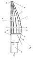
- FIG. 1 shows a rotor blade 10 with a blade root 12, a blade tip 14, a trailing edge 16 and a nose edge 18, wherein in an assembly, the blade root 12 is connected to the rotor hub of a wind turbine.
- the rotor blade has a varying blade depth b between the trailing edge and the nose edge. Starting from the blade root 12 of the rotor blade, the blade depth b increases to its maximum and then tapers continuously as far as the blade tip 14.
- an inventive belt system 7 is mounted on the rotor blade 10.
- the belt system 7 comprises a Clamping device 1, the blade root side extends around the rotor blade 10, and a fixing means 5, the blade tip side extends around the rotor blade 10. Furthermore, between the tensioning device 1 and the fixing means 5, a plurality of longitudinal belts 2 extending in the longitudinal direction of the sheet extend. In the transverse direction of the sheet, a plurality of transverse belts 3 extend, each of which is detachably connected to the longitudinal belts 2.
- the crossbar belt 3 closest to the blade root is arranged such that it is located at the blade tip side from the point at which the rotor blade has its maximum blade depth b.
- the longitudinal straps 2 hold aerodynamically effective disruptive bodies 6.
- the disruptive bodies 6 could also be arranged on the transverse straps 3 or on the transverse straps 3 and the longitudinal straps 2.
- An arrangement of the bluff body 6 between the transverse straps 3 and longitudinal straps 2 would also be possible, so that the bluff bodies 6 adjoin the transverse straps 3 and longitudinal straps 2.
- the bluff bodies 6 may be distributed along the entire circumference of the rotor blade 10. Alternatively, the bluff bodies 6 could be arranged on one side of the rotor blade 10. The distribution of the bluff body 6 is according to FIG. 1 in the area of the blade tip 14 denser than in the central region of the rotor blade. alternative to FIG. 1
- the bluff bodies 6 could be distributed unevenly on the rotor blade surface, ie more or fewer bluff bodies could be arranged in the middle region than in the region of the blade tip 14.
- the bluff body 6 may be formed differently long, wherein they are formed in the central blade area longer than in the region of the blade tip 14. Likewise, the bluff bodies 6 could be shorter in the middle blade area than in the area of the blade tip 14. Alternatively, the bluff body 6 could be formed differently wide or different widths and long.
- the longitudinal straps 2 and the cross straps 3 are connected to form a coherent network
- the longitudinal straps 3 and the cross straps 2 can be detachably or firmly connected to each other.
- only one longitudinal belt 2 could be detachably or firmly connected to the transverse straps 3 to form a coherent net, in which case the single longitudinal belt 2 runs meander-shaped on the surface of the rotor blade 10, that is, the only longitudinal belt 2 runs on the rotor blade 10 between the two Clamping device 1 and the fixing means 5 back and forth.
- the belt system 7 can be quickly and easily mounted on the rotor blade 10 to be mounted and removed again.
- the blade tip 14 has a fixing means 5, which, as in FIG. 1 shown fit exactly on the blade tip 14 is arranged.
- the fixing means 5 avoids slipping of the belt system 7 on the rotor blade 10 and thus contributes to the stabilization of the belt system 7 on the rotor blade 10 at.
- each transverse belt 3 has a trailing edge fixing 4, so that slippage of the transverse straps 3 is avoided.
- the transverse straps 3 are protected from being severed by the rear edge 16 due to slipping of the transverse straps 3 at the trailing edge 16.
- the tensioning device 1 has no trailing edge fixation 4.
- the tensioning device 1 could also have a trailing edge fixation 4.
- Fig. 2 also shows a rotor blade with the belt system 7 according to the invention.
- the fixing means 5 is designed as a second tensioning device 11.
- the second tensioning device 11 is located at a distance from the blade tip 14. It allows tensioning of the longitudinal straps 2 against the tensioning device 1. Due to the large length of a rotor blade, it is advantageous to be able to tension the belt system from two sides.
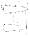
- FIG. 3 shows a cross section along the cutting plane AA.
- the cross-section of the rotor blade is shown simplified and does not correspond to the aerodynamic profile.
- the sectional plane AA is located in a region of the belt system 7, in which there are no obstructions.
- the longitudinal straps 3 are arranged at substantially uniform intervals on the circumference of the rotor blade.
- the blunt trailing edge 16 of the rotor blade is provided with a trailing edge fixing 4, which is adapted in shape to the geometry of the trailing edge 16.
- FIG. 4 shows a cross section along the section plane BB FIG. 1 ,
- the sectional plane extends through a region of the belt system 7, in which the bluff bodies 6 are arranged on the longitudinal belts 2.
- disturbing bodies are arranged essentially uniformly on the circumference of the rotor blade.
- the bluff bodies 6 have an elliptical body with a triangular cross-sectional area. It should be noted that in the FIGS. 1 to 5 the bluff bodies are shown schematically simplified. The bluff bodies can also have other shapes. Also conceivable are prism-shaped bluff bodies with a triangular or another polygonal or with a distorted or asymmetrical cross-sectional area. A semi-elliptical disruptive body would also be conceivable.
- the Bluff bodies consist of a relatively strong, closed-cell foam material. By cutting the pores on the surface of the bluff body creates a rough surface that promotes the interruption of a laminar flow. One of the bluff bodies is arranged in the region of the rear edge 16, as a result of which it receives additional protection.
- FIG. 5 shows a schematic representation of the assembly of a single rotor blade 10 on the rotor hub 22 of a wind energy 20.
- the provided with a belt system 7 rotor blade 10 is attached to the rotor blade 10 laid down slings 9 on a crossbar 8.
- a sling 9 is attached near the blade root end and another near the blade tip side end.
- the slings 9 are releasably connected to the crossbeam 8.
- the rotor blade is mounted lying horizontally on the rotor hub.
- the belt system 7 can be easily removed by relaxing the tensioning device 1 of the mounted rotor blade 10 and let down to the ground and be used for the assembly of another rotor blade 10.
Landscapes
- Engineering & Computer Science (AREA)
- Mechanical Engineering (AREA)
- Life Sciences & Earth Sciences (AREA)
- Sustainable Development (AREA)
- Sustainable Energy (AREA)
- Chemical & Material Sciences (AREA)
- Combustion & Propulsion (AREA)
- General Engineering & Computer Science (AREA)
- Wind Motors (AREA)
Applications Claiming Priority (1)
| Application Number | Priority Date | Filing Date | Title |
|---|---|---|---|
| DE102011111967A DE102011111967B3 (de) | 2011-08-31 | 2011-08-31 | Gurtsystem zur Einzelblattmontage eines Rotorblattes oder zur Sternmontage eines Rotors an einer Windenergieanlage sowie Verfahren hierzu |
Publications (2)
| Publication Number | Publication Date |
|---|---|
| EP2565440A2 true EP2565440A2 (fr) | 2013-03-06 |
| EP2565440A3 EP2565440A3 (fr) | 2014-08-20 |
Family
ID=46826202
Family Applications (1)
| Application Number | Title | Priority Date | Filing Date |
|---|---|---|---|
| EP12006143.7A Withdrawn EP2565440A3 (fr) | 2011-08-31 | 2012-08-29 | Harnais pour monter une unique pâle sur un rotor ou pour monter un rotor en étoile sur une éolienne et méthode associée |
Country Status (2)
| Country | Link |
|---|---|
| EP (1) | EP2565440A3 (fr) |
| DE (1) | DE102011111967B3 (fr) |
Cited By (16)
| Publication number | Priority date | Publication date | Assignee | Title |
|---|---|---|---|---|
| EP2570654A2 (fr) * | 2011-09-13 | 2013-03-20 | Nordex Energy GmbH | Dispositif de protection pour une pale d'éolienne |
| CN105927478A (zh) * | 2016-05-17 | 2016-09-07 | 江苏海上龙源风力发电有限公司 | 一种海上风机单叶片安装方法 |
| DE102017004058A1 (de) * | 2017-04-27 | 2018-10-31 | Senvion Gmbh | Rotorblatt einer windenergieanlage und verfahren zum herstellen eines solchen, abschlusssteg eines rotorblatts und verwendung eines solchen |
| CN110318957A (zh) * | 2019-07-23 | 2019-10-11 | 中科国风科技有限公司 | 一种风电叶片延长节防坠结构 |
| WO2020058099A1 (fr) * | 2018-09-17 | 2020-03-26 | Pp Energy Aps | Système de prévention d'intrusion d'eau pour aubes de turbine |
| CN113167232A (zh) * | 2018-12-13 | 2021-07-23 | 西门子歌美飒可再生能源公司 | 抑制风力涡轮机中的振动 |
| EP3885572A1 (fr) * | 2020-03-25 | 2021-09-29 | Siemens Gamesa Renewable Energy A/S | Réduction de charge aérodynamique pendant l'installation et le fonctionnement de pales dans une éolienne |
| CN113864111A (zh) * | 2021-11-15 | 2021-12-31 | 华能新能源股份有限公司山东分公司 | 一种风电叶片扰流装置及方法 |
| CN115285831A (zh) * | 2022-06-29 | 2022-11-04 | 国电联合动力技术有限公司 | 风力发电机组叶片更换系统及方法 |
| EP4160007A1 (fr) * | 2021-10-04 | 2023-04-05 | General Electric Renovables España S.L. | Dispositifs et procédés pour atténuer les vibrations dans des éoliennes |
| EP4160010A1 (fr) * | 2021-10-04 | 2023-04-05 | General Electric Renovables España S.L. | Dispositifs et procédés pour atténuer les vibrations dans des éoliennes |
| EP4160008A1 (fr) * | 2021-10-04 | 2023-04-05 | General Electric Renovables España S.L. | Dispositifs et procédés de réduction de vibrations sur des éoliennes |
| WO2023143681A1 (fr) * | 2022-01-25 | 2023-08-03 | Dansk Gummi Industri A/S | Patin de support pour pale d'éolienne |
| US20240263610A1 (en) * | 2021-07-23 | 2024-08-08 | Lm Wind Power A/S | Devices and methods for mitigating vibrations in wind turbine blades |
| US12196181B2 (en) | 2020-11-10 | 2025-01-14 | Pp Energy Aps | Temporary enclosure for at least a part of a rotor blade |
| US12473893B2 (en) | 2022-01-24 | 2025-11-18 | Pp Energy Aps | Wind turbine blade maintenance platform |
Families Citing this family (6)
| Publication number | Priority date | Publication date | Assignee | Title |
|---|---|---|---|---|
| EP3112667B1 (fr) * | 2015-06-30 | 2020-08-26 | Vestas Wind Systems A/S | Outil anti-oscillation |
| CN105947890B8 (zh) * | 2016-06-24 | 2017-12-22 | 成都世唯科技有限公司 | 一种风力发电机用叶吊具的偏摆机构 |
| WO2020058086A1 (fr) * | 2018-09-17 | 2020-03-26 | Pp Energy Aps | Harnais de levage |
| CN112211789A (zh) * | 2020-10-22 | 2021-01-12 | 华能新能源股份有限公司河北分公司 | 一种单叶片吊装方法 |
| EP4399410A1 (fr) | 2021-09-08 | 2024-07-17 | Vestas Wind Systems A/S | Outil anti-oscillation |
| CN119929650B (zh) * | 2025-04-09 | 2025-06-10 | 成都城投城建科技有限公司 | 一种预制盖板吊装装置 |
Citations (3)
| Publication number | Priority date | Publication date | Assignee | Title |
|---|---|---|---|---|
| EP2224126A2 (fr) | 2009-02-25 | 2010-09-01 | General Electric Company | Procédé de manipulation d'une pale d'éolienne à position verticale |
| EP1794451B1 (fr) | 2004-09-18 | 2011-04-06 | Aloys Wobben | Dispositif de marquage d'une eolienne |
| WO2011067304A1 (fr) | 2009-12-02 | 2011-06-09 | Vestas Wind Systems A/S | Appareil anti-oscillation et technique visant à protéger des oscillations les pales d'une éolienne |
Family Cites Families (2)
| Publication number | Priority date | Publication date | Assignee | Title |
|---|---|---|---|---|
| DE20109835U1 (de) * | 2001-06-15 | 2002-01-24 | Gerken GmbH, 40599 Düsseldorf | Arbeitsbühne |
| ES2257558T3 (es) * | 2002-05-27 | 2006-08-01 | Vestas Wind Systems A/S | Metodos de manipulacion de palas de turbinas eolicas y de montaje de dichas palas en una turbina eolica, sistema y unidad de agarre para manipular una pala de turbina eolica. |
-
2011
- 2011-08-31 DE DE102011111967A patent/DE102011111967B3/de not_active Expired - Fee Related
-
2012
- 2012-08-29 EP EP12006143.7A patent/EP2565440A3/fr not_active Withdrawn
Patent Citations (3)
| Publication number | Priority date | Publication date | Assignee | Title |
|---|---|---|---|---|
| EP1794451B1 (fr) | 2004-09-18 | 2011-04-06 | Aloys Wobben | Dispositif de marquage d'une eolienne |
| EP2224126A2 (fr) | 2009-02-25 | 2010-09-01 | General Electric Company | Procédé de manipulation d'une pale d'éolienne à position verticale |
| WO2011067304A1 (fr) | 2009-12-02 | 2011-06-09 | Vestas Wind Systems A/S | Appareil anti-oscillation et technique visant à protéger des oscillations les pales d'une éolienne |
Cited By (23)
| Publication number | Priority date | Publication date | Assignee | Title |
|---|---|---|---|---|
| EP2570654A2 (fr) * | 2011-09-13 | 2013-03-20 | Nordex Energy GmbH | Dispositif de protection pour une pale d'éolienne |
| CN105927478A (zh) * | 2016-05-17 | 2016-09-07 | 江苏海上龙源风力发电有限公司 | 一种海上风机单叶片安装方法 |
| DE102017004058A1 (de) * | 2017-04-27 | 2018-10-31 | Senvion Gmbh | Rotorblatt einer windenergieanlage und verfahren zum herstellen eines solchen, abschlusssteg eines rotorblatts und verwendung eines solchen |
| US11525435B2 (en) | 2018-09-17 | 2022-12-13 | Pp Energy Aps | Water intrusion prevention system for turbine blades |
| WO2020058099A1 (fr) * | 2018-09-17 | 2020-03-26 | Pp Energy Aps | Système de prévention d'intrusion d'eau pour aubes de turbine |
| CN113167232A (zh) * | 2018-12-13 | 2021-07-23 | 西门子歌美飒可再生能源公司 | 抑制风力涡轮机中的振动 |
| CN110318957A (zh) * | 2019-07-23 | 2019-10-11 | 中科国风科技有限公司 | 一种风电叶片延长节防坠结构 |
| EP3885572A1 (fr) * | 2020-03-25 | 2021-09-29 | Siemens Gamesa Renewable Energy A/S | Réduction de charge aérodynamique pendant l'installation et le fonctionnement de pales dans une éolienne |
| WO2021190891A1 (fr) * | 2020-03-25 | 2021-09-30 | Siemens Gamesa Renewable Energy A/S | Réduction de charge aérodynamique pendant l'installation et l'entretion de pale dans une éolienne |
| US12196181B2 (en) | 2020-11-10 | 2025-01-14 | Pp Energy Aps | Temporary enclosure for at least a part of a rotor blade |
| US12435695B2 (en) * | 2021-07-23 | 2025-10-07 | Lm Wind Power A/S | Devices and methods for mitigating vibrations in wind turbine blades |
| US20240263610A1 (en) * | 2021-07-23 | 2024-08-08 | Lm Wind Power A/S | Devices and methods for mitigating vibrations in wind turbine blades |
| US11686293B2 (en) | 2021-10-04 | 2023-06-27 | General Electric Renovables Espana, S.L. | Devices and methods for mitigating vibrations in wind turbines |
| EP4160008A1 (fr) * | 2021-10-04 | 2023-04-05 | General Electric Renovables España S.L. | Dispositifs et procédés de réduction de vibrations sur des éoliennes |
| EP4160010A1 (fr) * | 2021-10-04 | 2023-04-05 | General Electric Renovables España S.L. | Dispositifs et procédés pour atténuer les vibrations dans des éoliennes |
| US11959456B2 (en) | 2021-10-04 | 2024-04-16 | General Electric Renovables Espana, S.L. | Devices and methods for vibration mitigation on wind turbines |
| EP4160007A1 (fr) * | 2021-10-04 | 2023-04-05 | General Electric Renovables España S.L. | Dispositifs et procédés pour atténuer les vibrations dans des éoliennes |
| US12071924B2 (en) | 2021-10-04 | 2024-08-27 | General Electric Renovables Espana, S.L. | Devices and methods for mitigating vibrations in wind turbines |
| CN113864111B (zh) * | 2021-11-15 | 2025-05-27 | 华能新能源股份有限公司山东分公司 | 一种风电叶片扰流装置及方法 |
| CN113864111A (zh) * | 2021-11-15 | 2021-12-31 | 华能新能源股份有限公司山东分公司 | 一种风电叶片扰流装置及方法 |
| US12473893B2 (en) | 2022-01-24 | 2025-11-18 | Pp Energy Aps | Wind turbine blade maintenance platform |
| WO2023143681A1 (fr) * | 2022-01-25 | 2023-08-03 | Dansk Gummi Industri A/S | Patin de support pour pale d'éolienne |
| CN115285831A (zh) * | 2022-06-29 | 2022-11-04 | 国电联合动力技术有限公司 | 风力发电机组叶片更换系统及方法 |
Also Published As
| Publication number | Publication date |
|---|---|
| DE102011111967B3 (de) | 2013-01-10 |
| EP2565440A3 (fr) | 2014-08-20 |
Similar Documents
| Publication | Publication Date | Title |
|---|---|---|
| DE102011111967B3 (de) | Gurtsystem zur Einzelblattmontage eines Rotorblattes oder zur Sternmontage eines Rotors an einer Windenergieanlage sowie Verfahren hierzu | |
| EP2532883B1 (fr) | Composant d'éolienne avec un câble électrique incorporé dans un laminage | |
| DE202010003033U1 (de) | Hebezeug zur Positionierung eines Rotorblatts einer Windenergieanlage | |
| EP2261501A2 (fr) | Méthode et dispositif de montage d'une pale de rotor pour une éolienne | |
| EP2550225B1 (fr) | Élévateur d'un rotor d'une turbine éolienne | |
| EP2445788A1 (fr) | Dispositif de soulèvement de charge pour un hélicoptère | |
| EP2273101A1 (fr) | Procédé d'assemblage des aubes d'une éolienne | |
| DE2021040A1 (de) | Laststabilisierungsvorrichtung | |
| DE102009005632B4 (de) | Handhabung von Rotorblättern | |
| DE102008019680A1 (de) | Vorrichtung zum Ermöglichen des Zugangs zu einer sich hoch über den Boden erstreckenden Anordnung und Verfahren zum Installieren einer solchen Vorrichtung | |
| EP2984334B1 (fr) | Pale de rotor d'éolienne et éolienne | |
| DE102021113314B4 (de) | Hubsystem und -verfahren für einen Kran | |
| EP3499027B1 (fr) | Dispositifs de transport des pales de rotor d'une éolienne | |
| DE102017127035A1 (de) | Flanschgestell und Montageset zur Vormontage und/oder zum Transport und/oder zur Montage eines Turmsegments für eine Windenergieanlage sowie Verfahren | |
| EP2452034B1 (fr) | Dispositif à enroulement pour l'occlusion d'ouvertures pratiquées dans des murs ou de fenêtres | |
| EP3514099B1 (fr) | Dispositif de fixation d'un câble de grue ou de guidage sur une pale de rotor d'une éolienne | |
| DE202018003615U1 (de) | Scruton-Spirale | |
| DE102011113482B4 (de) | Schutzeinrichtung für ein Rotorblatt einer Windenergieanlage | |
| DE102010060639A1 (de) | Arbeitsbühnenanlage | |
| DE102016222211A1 (de) | Hebeanordnung | |
| DE102010002720A1 (de) | Windenergieanlagen-Rotorblatt | |
| DE20109835U1 (de) | Arbeitsbühne | |
| EP4257387A1 (fr) | Système de recouvrement | |
| DE112010005542T5 (de) | Anhängeseilhalterung für Nabenhub | |
| EP3319898B1 (fr) | Grue à tour |
Legal Events
| Date | Code | Title | Description |
|---|---|---|---|
| PUAI | Public reference made under article 153(3) epc to a published international application that has entered the european phase |
Free format text: ORIGINAL CODE: 0009012 |
|
| AK | Designated contracting states |
Kind code of ref document: A2 Designated state(s): AL AT BE BG CH CY CZ DE DK EE ES FI FR GB GR HR HU IE IS IT LI LT LU LV MC MK MT NL NO PL PT RO RS SE SI SK SM TR |
|
| AX | Request for extension of the european patent |
Extension state: BA ME |
|
| PUAL | Search report despatched |
Free format text: ORIGINAL CODE: 0009013 |
|
| AK | Designated contracting states |
Kind code of ref document: A3 Designated state(s): AL AT BE BG CH CY CZ DE DK EE ES FI FR GB GR HR HU IE IS IT LI LT LU LV MC MK MT NL NO PL PT RO RS SE SI SK SM TR |
|
| AX | Request for extension of the european patent |
Extension state: BA ME |
|
| RIC1 | Information provided on ipc code assigned before grant |
Ipc: B66C 1/10 20060101ALI20140716BHEP Ipc: F03D 1/00 20060101AFI20140716BHEP |
|
| 17P | Request for examination filed |
Effective date: 20150220 |
|
| RBV | Designated contracting states (corrected) |
Designated state(s): AL AT BE BG CH CY CZ DE DK EE ES FI FR GB GR HR HU IE IS IT LI LT LU LV MC MK MT NL NO PL PT RO RS SE SI SK SM TR |
|
| GRAP | Despatch of communication of intention to grant a patent |
Free format text: ORIGINAL CODE: EPIDOSNIGR1 |
|
| STAA | Information on the status of an ep patent application or granted ep patent |
Free format text: STATUS: GRANT OF PATENT IS INTENDED |
|
| RIC1 | Information provided on ipc code assigned before grant |
Ipc: B66C 1/10 20060101ALI20170214BHEP Ipc: F03D 1/00 20060101AFI20170214BHEP Ipc: F03D 13/10 20160101ALI20170214BHEP |
|
| INTG | Intention to grant announced |
Effective date: 20170308 |
|
| GRAJ | Information related to disapproval of communication of intention to grant by the applicant or resumption of examination proceedings by the epo deleted |
Free format text: ORIGINAL CODE: EPIDOSDIGR1 |
|
| STAA | Information on the status of an ep patent application or granted ep patent |
Free format text: STATUS: REQUEST FOR EXAMINATION WAS MADE |
|
| STAA | Information on the status of an ep patent application or granted ep patent |
Free format text: STATUS: EXAMINATION IS IN PROGRESS |
|
| INTC | Intention to grant announced (deleted) | ||
| 17Q | First examination report despatched |
Effective date: 20170802 |
|
| GRAP | Despatch of communication of intention to grant a patent |
Free format text: ORIGINAL CODE: EPIDOSNIGR1 |
|
| STAA | Information on the status of an ep patent application or granted ep patent |
Free format text: STATUS: GRANT OF PATENT IS INTENDED |
|
| INTG | Intention to grant announced |
Effective date: 20180829 |
|
| GRAJ | Information related to disapproval of communication of intention to grant by the applicant or resumption of examination proceedings by the epo deleted |
Free format text: ORIGINAL CODE: EPIDOSDIGR1 |
|
| STAA | Information on the status of an ep patent application or granted ep patent |
Free format text: STATUS: EXAMINATION IS IN PROGRESS |
|
| GRAP | Despatch of communication of intention to grant a patent |
Free format text: ORIGINAL CODE: EPIDOSNIGR1 |
|
| STAA | Information on the status of an ep patent application or granted ep patent |
Free format text: STATUS: GRANT OF PATENT IS INTENDED |
|
| INTC | Intention to grant announced (deleted) | ||
| INTG | Intention to grant announced |
Effective date: 20190116 |
|
| RIC1 | Information provided on ipc code assigned before grant |
Ipc: B66C 1/10 20060101ALI20170214BHEP Ipc: F03D 1/00 20060101AFI20170214BHEP Ipc: F03D 13/10 20160101ALI20170214BHEP |
|
| STAA | Information on the status of an ep patent application or granted ep patent |
Free format text: STATUS: THE APPLICATION IS DEEMED TO BE WITHDRAWN |
|
| 18D | Application deemed to be withdrawn |
Effective date: 20190528 |