EP2565465A1 - Verfahren und Vorrichtung zur Bestimmung der Massenänderung eines Lüfterrads - Google Patents
Verfahren und Vorrichtung zur Bestimmung der Massenänderung eines Lüfterrads Download PDFInfo
- Publication number
- EP2565465A1 EP2565465A1 EP11179147A EP11179147A EP2565465A1 EP 2565465 A1 EP2565465 A1 EP 2565465A1 EP 11179147 A EP11179147 A EP 11179147A EP 11179147 A EP11179147 A EP 11179147A EP 2565465 A1 EP2565465 A1 EP 2565465A1
- Authority
- EP
- European Patent Office
- Prior art keywords
- angular speed
- mass
- fan impeller
- parameter
- change
- Prior art date
- Legal status (The legal status is an assumption and is not a legal conclusion. Google has not performed a legal analysis and makes no representation as to the accuracy of the status listed.)
- Granted
Links
Images

Classifications
-
- F—MECHANICAL ENGINEERING; LIGHTING; HEATING; WEAPONS; BLASTING
- F04—POSITIVE - DISPLACEMENT MACHINES FOR LIQUIDS; PUMPS FOR LIQUIDS OR ELASTIC FLUIDS
- F04D—NON-POSITIVE-DISPLACEMENT PUMPS
- F04D27/00—Control, e.g. regulation, of pumps, pumping installations or pumping systems specially adapted for elastic fluids
- F04D27/001—Testing thereof; Determination or simulation of flow characteristics; Stall or surge detection, e.g. condition monitoring
-
- F—MECHANICAL ENGINEERING; LIGHTING; HEATING; WEAPONS; BLASTING
- F04—POSITIVE - DISPLACEMENT MACHINES FOR LIQUIDS; PUMPS FOR LIQUIDS OR ELASTIC FLUIDS
- F04D—NON-POSITIVE-DISPLACEMENT PUMPS
- F04D25/00—Pumping installations or systems
- F04D25/02—Units comprising pumps and their driving means
- F04D25/06—Units comprising pumps and their driving means the pump being electrically driven
-
- F—MECHANICAL ENGINEERING; LIGHTING; HEATING; WEAPONS; BLASTING
- F04—POSITIVE - DISPLACEMENT MACHINES FOR LIQUIDS; PUMPS FOR LIQUIDS OR ELASTIC FLUIDS
- F04D—NON-POSITIVE-DISPLACEMENT PUMPS
- F04D25/00—Pumping installations or systems
- F04D25/02—Units comprising pumps and their driving means
- F04D25/08—Units comprising pumps and their driving means the working fluid being air, e.g. for ventilation
-
- F—MECHANICAL ENGINEERING; LIGHTING; HEATING; WEAPONS; BLASTING
- F04—POSITIVE - DISPLACEMENT MACHINES FOR LIQUIDS; PUMPS FOR LIQUIDS OR ELASTIC FLUIDS
- F04D—NON-POSITIVE-DISPLACEMENT PUMPS
- F04D29/00—Details, component parts, or accessories
- F04D29/70—Suction grids; Strainers; Dust separation; Cleaning
- F04D29/701—Suction grids; Strainers; Dust separation; Cleaning especially adapted for elastic fluid pumps
- F04D29/703—Suction grids; Strainers; Dust separation; Cleaning especially adapted for elastic fluid pumps specially for fans, e.g. fan guards
-
- H—ELECTRICITY
- H02—GENERATION; CONVERSION OR DISTRIBUTION OF ELECTRIC POWER
- H02P—CONTROL OR REGULATION OF ELECTRIC MOTORS, ELECTRIC GENERATORS OR DYNAMO-ELECTRIC CONVERTERS; CONTROLLING TRANSFORMERS, REACTORS OR CHOKE COILS
- H02P21/00—Arrangements or methods for the control of electric machines by vector control, e.g. by control of field orientation
- H02P21/14—Estimation or adaptation of machine parameters, e.g. flux, current or voltage
- H02P21/143—Inertia or moment of inertia estimation
-
- H—ELECTRICITY
- H02—GENERATION; CONVERSION OR DISTRIBUTION OF ELECTRIC POWER
- H02P—CONTROL OR REGULATION OF ELECTRIC MOTORS, ELECTRIC GENERATORS OR DYNAMO-ELECTRIC CONVERTERS; CONTROLLING TRANSFORMERS, REACTORS OR CHOKE COILS
- H02P23/00—Arrangements or methods for the control of AC motors characterised by a control method other than vector control
- H02P23/14—Estimation or adaptation of motor parameters, e.g. rotor time constant, flux, speed, current or voltage
Definitions
- the present invention relates to a fan and particularly to detecting a change in the mass of a fan impeller.
- Fans are widely used in a large variety of applications and operating conditions. They are often used for ventilating contaminated air and exhaust of combustion gases. In these applications, small particles, such as soot, may accumulate on the fan impeller and gradually cause a decrease in the efficiency of the fan.
- a change in the mass of a fan impeller can be detected by using a method which is based on the idea that the moment of inertia of the fan increases as contaminants increase the mass of the fan impeller.
- the moment of inertia is inversely proportional to the derivate of the angular speed of the fan impeller as a function of time when a torque is applied to the fan. In other words, as the moment of inertia of the fan increases, the derivate of the angular speed of the fan decreases.
- a fluid transferred by the fan may have an effect on the measurement.
- the derivate may be determined by using a low angular speed range where the torque required by the moment of inertia of the fan is much greater than the torque required to transfer the fluid.
- a frequency converter may be utilized in detecting the build-up of additional mass. By using a frequency converter powering the fan, it is possible to detect a build-up of a contaminant or contaminants without extra instrumentation also when the fan is otherwise operating in a normal and healthy state.
- T J ⁇ d ⁇ dt
- the mass of a fan impeller can be estimated using Equation 1, if the torque T and the time derivate of an angular speed induced by the torque are known.
- a known torque T may first be induced to the fan impeller.
- the torque T may be induced on the basis of a set torque reference pattern.
- a change in an angular speed ⁇ of the fan impeller induced by the torque may then be determined, for instance, by measuring.
- the change may, for instance, be represented in a form of time derivate of the angular speed ⁇ .
- the change of the angular speed may, for instance, be calculated on the basis of a measured angular speed ⁇ .
- the time derivate of the angular speed can be determined, for instance, by directly measuring an acceleration induced by the torque.
- a moment of inertia J can be determined on the basis of the torque T and the change in the angular speed ⁇ . Because a moment of inertia is proportional to a mass, the mass of the fan impeller may be represented in the form of the moment of inertia J .
- Equation 1 may be used to determine a change in the mass caused by, for instance, a contaminant accumulating on a fan impeller.
- a value for a first parameter representing the present mass of the fan impeller may be determined on the basis of the torque and the change in the angular speed.
- the torque may be measured or estimated.
- a torque reference of a controller producing the torque can also be used to represent an estimate of the torque.
- the change in the mass may then be determined on the basis of the first parameter and a second parameter representing a reference mass of the fan impeller.
- the value of the first parameter may be sequentially updated and compared to a set value of the second parameter.
- the second parameter may be used to indicate a maximum limit for the mass of the fan impeller. If the value of the first parameter exceeds the second parameter, a notification may be issued.
- a change in the mass determined on the basis of the first parameter and the second parameter may then be compared with the third parameter, and if the change in the mass exceeds the third parameter, a notification may be issued.
- the change in the mass may, in some embodiments of the disclosed method, be represented in the form of a change ⁇ J in the moment of inertia.
- the first parameter and the second parameter are represented in the form of a moment of inertia J .
- the first parameter, the second parameter, and the third parameter may also be represented directly by a mass.
- a similar method can be used to estimate a change ⁇ m in the mass caused by the contaminant.
- the total moment of inertia can be seen as an arithmetic sum of individual moments of inertia.
- the change ⁇ m in the mass can be estimated.
- a torque T with a step pattern may be used in order to determine the time derivate of the angular speed ⁇ .
- the torque T is induced to the fan impeller by using a constant torque reference.
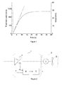
- Figure 1 illustrates an example of a change in the angular speed in response to an applied stepwise torque.
- a combined effect of a moment of inertia of a fan and the torque requirement for a fluid transferred at the angular speed is shown.
- the angular speed increases substantially linearly to a speed of 400 rpm.
- the torque required to transfer the fluid becomes more dominant, and the rate of change of the angular speed is no longer linear.
- Figure 2 illustrates an exemplary apparatus 1 for estimating a change in the mass of a fan impeller.
- the apparatus comprises a frequency converter 2 powering a fan 3.
- the frequency converter 2 supplies power to a fan motor 4 of the fan 3.
- the fan motor 4 rotates a fan impeller 5.
- the frequency converter 2 acts as a means for inducing a torque to the fan impeller 5.
- the apparatus 1 further comprises an estimator 6, which produces a value representing the mass of the fan impeller 5.
- the estimator 6 determines a change in the angular speed of the fan impeller induced by the torque by using the angular speed information provided by the frequency converter 2.
- the estimator 6 then calculates a value for a first parameter representing the present mass of the fan impeller on the basis of a change in the angular speed of the fan impeller and the torque.
- a reference sequence for determining a reference may be executed.
- a value for the second parameter may be set during this sequence.
- a value for a third parameter representing a maximum allowable change in the mass may also be set.
- the reference sequence may, for instance, take place during commissioning or after a fan impeller clean-up.
- a first value of the first parameter determined after a fan has been installed or cleaned may be used as the value of the second parameter.
- the first parameter representing the present mass of the fan impeller can be determined using the method disclosed above.
- a detection sequence is initiated.
- a change in the mass may be determined on the basis of a torque induced to the fan impeller and a change in the angular speed of the fan impeller induced by the torque as disclosed above.
- the difference between the values of the first parameter and the value of the second parameter may be calculated.
- the difference represents a change in the mass of the fan impeller.
- the difference may then be compared with the third parameter, and if the difference exceeds the third parameter, a notification may be issued.
- the first parameter may be compared with the second parameter indicating a maximum limit for the mass of the fan impeller, and, if the first parameter exceeds the second parameter, a notification may be issued.
- Figure 3 illustrates an exemplary flow chart for the operation of the apparatus of Figure 2 .
- the reference sequence and the detection sequence share some of the steps in Figure 3 .
- step 13 the value of the first parameter representing the present mass is determined.
- a time derivate of the angular speed may be calculated on the basis of the angular speed.
- the samples may be filtered in order to remove possible noise and clearly erroneous samples.
- the filtering may, for instance, be implemented using a 20-point median filter having a time period of 0.2 s.
- a new data set where the angular speed is between a lower limit and an upper limit may be formed out of the filtered samples.
- a slope k representing the time derivate of the angular speed can then be calculated from the data set by using, for instance, the method of the sum of least squares.
- the value for the first parameter may be determined on the basis of the slope k. Since the torque follows a known step pattern, the value of the slope k may itself be used as an indicator of the mass of the fan impeller. In other words, the first and second parameter may be represented in the form of the time derivate of the angular speed. Slope k is inversely proportional to the contamination build-up. As the amount of a contaminant starts to build up, the value of k decreases.
- the disclosed method may also be used to detect a decrease in the mass of the fan impeller.
- a contaminant may grind the fan impeller, causing the mass of the fan impeller to decrease. This can be seen as a reduction in the moment of inertia of the fan impeller.
- a loss in the mass may be seen as an increase in the value of the slope k , or as a decrease in the values of the moment of inertia J or the mass m.
- step 14 If the value of the first parameter is calculated for the first time, for instance, after a fan has been installed or cleaned, the value is set as the value of the second parameter in step 15. The reference sequence is now finished and the detection sequence begins.
- the watchdog of the apparatus may, for instance, send a warning message to the user that there is a contamination build-up in the fan, which causes the change in the mass of the fan impeller to exceed its maximum allowable limit.
- the mass increases were 0 g, 50 g, 104 g and 151 g.
- the moments of inertia caused by the added masses were 0 kgm 2 , 0.005 kgm 2 , 0.010 kgm 2 , and 0.015 kgm 2 , respectively.
- the inertia of the fan impeller used was 1.26 kgm 2 according to the manufacturer.
- increases of the moment of inertia of the fan impeller were 0%, 0.4%, 0.8%, and 1.2%, respectively.
- the tests were done using different valve positions and torque reference values.
- the results indicate that the torque reference used for the acceleration of the fan impeller did not have a significant effect on the analysis results for indicating a change ( ⁇ J / J 0g ) in the moment of inertia.
- the torque reference is not constrained to a certain level when using the disclosed method.
- the effect of the fan operating point may be minimized by using the same upper and lower angular speed limits in the reference sequence and the detection sequence.
- the estimation of the increase in the mass was quite accurate, as shown in Table 4.
- the relatively accurate result may, in part, be a consequence of the assumption that all of the mass is at a certain distance from the axis of rotation. In real applications, the situation may not be as simple.
Landscapes
- Engineering & Computer Science (AREA)
- Mechanical Engineering (AREA)
- General Engineering & Computer Science (AREA)
- Power Engineering (AREA)
- Control Of Positive-Displacement Air Blowers (AREA)
- Structures Of Non-Positive Displacement Pumps (AREA)
Priority Applications (3)
| Application Number | Priority Date | Filing Date | Title |
|---|---|---|---|
| EP20110179147 EP2565465B1 (de) | 2011-08-29 | 2011-08-29 | Verfahren und Vorrichtung zur Bestimmung der Massenänderung eines Lüfterrads |
| US13/590,708 US9021876B2 (en) | 2011-08-29 | 2012-08-21 | Method and apparatus for determining change in mass of fan impeller |
| CN201210311172.1A CN102966582B (zh) | 2011-08-29 | 2012-08-28 | 用于确定风机叶轮的质量变化的方法和设备 |
Applications Claiming Priority (1)
| Application Number | Priority Date | Filing Date | Title |
|---|---|---|---|
| EP20110179147 EP2565465B1 (de) | 2011-08-29 | 2011-08-29 | Verfahren und Vorrichtung zur Bestimmung der Massenänderung eines Lüfterrads |
Publications (3)
| Publication Number | Publication Date |
|---|---|
| EP2565465A1 true EP2565465A1 (de) | 2013-03-06 |
| EP2565465A9 EP2565465A9 (de) | 2013-06-05 |
| EP2565465B1 EP2565465B1 (de) | 2014-12-10 |
Family
ID=44653181
Family Applications (1)
| Application Number | Title | Priority Date | Filing Date |
|---|---|---|---|
| EP20110179147 Active EP2565465B1 (de) | 2011-08-29 | 2011-08-29 | Verfahren und Vorrichtung zur Bestimmung der Massenänderung eines Lüfterrads |
Country Status (3)
| Country | Link |
|---|---|
| US (1) | US9021876B2 (de) |
| EP (1) | EP2565465B1 (de) |
| CN (1) | CN102966582B (de) |
Cited By (2)
| Publication number | Priority date | Publication date | Assignee | Title |
|---|---|---|---|---|
| EP3199813A1 (de) * | 2016-01-28 | 2017-08-02 | ABB Technology Oy | Lade-/entladesteuerungsverfahren für verdichtersystem |
| CN111431454A (zh) * | 2020-04-28 | 2020-07-17 | 中山大洋电机股份有限公司 | 无位置传感器矢量控制永磁电机估算转速可靠性判断方法 |
Families Citing this family (4)
| Publication number | Priority date | Publication date | Assignee | Title |
|---|---|---|---|---|
| CN110568950B (zh) * | 2018-06-05 | 2023-08-01 | 鸿富锦精密工业(深圳)有限公司 | Tft基板及触控显示面板 |
| CN110735812B (zh) * | 2019-09-05 | 2021-01-15 | 宁波方太厨具有限公司 | 一种吸油烟机的叶轮免人工保养的控制方法 |
| DE102020133000A1 (de) * | 2020-12-10 | 2022-06-15 | Ebm-Papst Landshut Gmbh | Verfahren zur Bestimmung und Erkennung von Zuständen, Zustandsänderungen und Fehlern einer Strömungsmaschine |
| CN115441796B (zh) * | 2021-06-02 | 2025-11-14 | 台达电子工业股份有限公司 | 基于负载转矩-转动惯量自学习模型的速度控制方法 |
Citations (4)
| Publication number | Priority date | Publication date | Assignee | Title |
|---|---|---|---|---|
| EP0476588A1 (de) * | 1990-09-21 | 1992-03-25 | Hitachi, Ltd. | Verfahren und Vorrichtung zur Berechnung des Trägheitsmoments bei einem Motorgeschwindigkeitsregler und Verfahren und Vorrichtung zur Geschwindigkeitsregelung eines Motors |
| JP2002267249A (ja) * | 2001-03-09 | 2002-09-18 | Sharp Corp | 流体送り装置 |
| EP1388732A1 (de) * | 2002-08-08 | 2004-02-11 | Dr. Johannes Heidenhain GmbH | Verfahren zur Bestimmung des Massenträgheitsmomentes eines elektromotorischen Antriebssystems |
| EP2135660A1 (de) * | 2008-06-17 | 2009-12-23 | Atlantic Climatisation et Ventilation | Verfahren zur Bestimmung des Verschmutzungsniveaus von Luftfiltern |
Family Cites Families (9)
| Publication number | Priority date | Publication date | Assignee | Title |
|---|---|---|---|---|
| SU488143A1 (ru) * | 1973-06-22 | 1975-10-15 | Предприятие П/Я А-1891 | Датчик ускорений |
| GB2090340B (en) * | 1980-12-31 | 1984-07-18 | Sueddeutsche Kuehler Behr | Radial fan wheel |
| SU1059466A1 (ru) * | 1982-05-10 | 1983-12-07 | Институт Проблем Машиностроения Ан Усср | Устройство дл испытани лопаток осевых вентил торов |
| JPS6188780A (ja) * | 1984-10-08 | 1986-05-07 | Hitachi Ltd | 速度制御装置の制御定数設定方法 |
| CN1021928C (zh) * | 1987-04-10 | 1993-08-25 | 广东机械学院 | 异步电动机机械特性电脑测试仪 |
| JP3632748B2 (ja) * | 2000-03-21 | 2005-03-23 | 日立プラント建設株式会社 | 汚染物質の固体表面吸着評価方法 |
| DE102009022720B4 (de) * | 2009-05-26 | 2020-11-05 | Sew-Eurodrive Gmbh & Co Kg | Lüfteranordnung |
| CN101749256B (zh) * | 2010-01-08 | 2013-11-13 | 浙江大学 | 基于自相关的大型轴流风机不平衡量的识别方法 |
| JP5168342B2 (ja) * | 2010-11-05 | 2013-03-21 | パナソニック株式会社 | 天井扇風機の安全装置 |
-
2011
- 2011-08-29 EP EP20110179147 patent/EP2565465B1/de active Active
-
2012
- 2012-08-21 US US13/590,708 patent/US9021876B2/en active Active
- 2012-08-28 CN CN201210311172.1A patent/CN102966582B/zh active Active
Patent Citations (4)
| Publication number | Priority date | Publication date | Assignee | Title |
|---|---|---|---|---|
| EP0476588A1 (de) * | 1990-09-21 | 1992-03-25 | Hitachi, Ltd. | Verfahren und Vorrichtung zur Berechnung des Trägheitsmoments bei einem Motorgeschwindigkeitsregler und Verfahren und Vorrichtung zur Geschwindigkeitsregelung eines Motors |
| JP2002267249A (ja) * | 2001-03-09 | 2002-09-18 | Sharp Corp | 流体送り装置 |
| EP1388732A1 (de) * | 2002-08-08 | 2004-02-11 | Dr. Johannes Heidenhain GmbH | Verfahren zur Bestimmung des Massenträgheitsmomentes eines elektromotorischen Antriebssystems |
| EP2135660A1 (de) * | 2008-06-17 | 2009-12-23 | Atlantic Climatisation et Ventilation | Verfahren zur Bestimmung des Verschmutzungsniveaus von Luftfiltern |
Cited By (3)
| Publication number | Priority date | Publication date | Assignee | Title |
|---|---|---|---|---|
| EP3199813A1 (de) * | 2016-01-28 | 2017-08-02 | ABB Technology Oy | Lade-/entladesteuerungsverfahren für verdichtersystem |
| US10451052B2 (en) | 2016-01-28 | 2019-10-22 | Abb Schweiz Ag | Load/unload control method for compressor system |
| CN111431454A (zh) * | 2020-04-28 | 2020-07-17 | 中山大洋电机股份有限公司 | 无位置传感器矢量控制永磁电机估算转速可靠性判断方法 |
Also Published As
| Publication number | Publication date |
|---|---|
| CN102966582A (zh) | 2013-03-13 |
| CN102966582B (zh) | 2015-09-30 |
| US20130047724A1 (en) | 2013-02-28 |
| EP2565465B1 (de) | 2014-12-10 |
| EP2565465A9 (de) | 2013-06-05 |
| US9021876B2 (en) | 2015-05-05 |
Similar Documents
| Publication | Publication Date | Title |
|---|---|---|
| EP2620202B1 (de) | Verfahren und Vorrichtung zum Überwachen des Luftfilterzustands | |
| EP2565465B1 (de) | Verfahren und Vorrichtung zur Bestimmung der Massenänderung eines Lüfterrads | |
| JP6154600B2 (ja) | 旋回失速を検出する方法及び装置と圧縮機 | |
| JPH08503042A (ja) | 軸流圧縮機の励振を監視するための方法および装置 | |
| GB2455798A (en) | Monitoring a rotating shaft in a gas turbine | |
| CN106537164A (zh) | 用于检测转子故障的方法与系统 | |
| CN112761980B (zh) | 一种评估动车组用冷却风机性能的方法及系统 | |
| US20100068070A1 (en) | Flow control for fluid handling system | |
| US20150166186A1 (en) | Aircraft air-conditioning heat exchanger contamination detection | |
| CN114216144A (zh) | 一种吸油烟机及其风机系统的叶轮清洁判定方法 | |
| EP3055661B1 (de) | Verfahren zur bestimmung der aktuellen exzentrizität eines rotierenden rotors und verfahren zur diagnose der exzentrizität des rotierenden rotors | |
| CN103134948A (zh) | 用于检测离心机的正确旋转方向的方法及离心机组件 | |
| US7743658B2 (en) | Method and device for identifying a damaged bearing of a rotating shaft | |
| JP2014214642A (ja) | 空気調和装置 | |
| CN110382878A (zh) | 确定用于预测压缩机中不稳定性的指标的方法和装置及其用途 | |
| EP2469098A1 (de) | Verfahren und vorrichtung zur vorhersage der instabilität eines axialkompressors | |
| Tamminen et al. | Detection of mass increase in a fan impeller with a frequency converter | |
| CN102734195B (zh) | 利用变频器的风机中的失速检测 | |
| CN103206387B (zh) | 用于检测离心设备的正确旋转方向的方法及离心设备组件 | |
| CN105136394A (zh) | 快速处理锅炉风机振动故障的方法及装置 | |
| CN120120278A (zh) | 风机动平衡调整方法 | |
| WO2013169508A1 (en) | Exhaust-gas turbocharger | |
| WO2013159458A1 (zh) | 一种电机及空调风机系统的恒风量控制方法 | |
| JP7792320B2 (ja) | 回転体および軸受を含む装置の予兆診断方法および装置 | |
| CN111742146A (zh) | 参数稳定性 |
Legal Events
| Date | Code | Title | Description |
|---|---|---|---|
| PUAI | Public reference made under article 153(3) epc to a published international application that has entered the european phase |
Free format text: ORIGINAL CODE: 0009012 |
|
| AK | Designated contracting states |
Kind code of ref document: A1 Designated state(s): AL AT BE BG CH CY CZ DE DK EE ES FI FR GB GR HR HU IE IS IT LI LT LU LV MC MK MT NL NO PL PT RO RS SE SI SK SM TR |
|
| AX | Request for extension of the european patent |
Extension state: BA ME |
|
| 17P | Request for examination filed |
Effective date: 20130821 |
|
| RBV | Designated contracting states (corrected) |
Designated state(s): AL AT BE BG CH CY CZ DE DK EE ES FI FR GB GR HR HU IE IS IT LI LT LU LV MC MK MT NL NO PL PT RO RS SE SI SK SM TR |
|
| GRAP | Despatch of communication of intention to grant a patent |
Free format text: ORIGINAL CODE: EPIDOSNIGR1 |
|
| INTG | Intention to grant announced |
Effective date: 20140703 |
|
| GRAS | Grant fee paid |
Free format text: ORIGINAL CODE: EPIDOSNIGR3 |
|
| GRAA | (expected) grant |
Free format text: ORIGINAL CODE: 0009210 |
|
| AK | Designated contracting states |
Kind code of ref document: B1 Designated state(s): AL AT BE BG CH CY CZ DE DK EE ES FI FR GB GR HR HU IE IS IT LI LT LU LV MC MK MT NL NO PL PT RO RS SE SI SK SM TR |
|
| REG | Reference to a national code |
Ref country code: GB Ref legal event code: FG4D |
|
| REG | Reference to a national code |
Ref country code: CH Ref legal event code: EP |
|
| REG | Reference to a national code |
Ref country code: IE Ref legal event code: FG4D |
|
| REG | Reference to a national code |
Ref country code: AT Ref legal event code: REF Ref document number: 700808 Country of ref document: AT Kind code of ref document: T Effective date: 20150115 |
|
| REG | Reference to a national code |
Ref country code: DE Ref legal event code: R096 Ref document number: 602011012073 Country of ref document: DE Effective date: 20150122 |
|
| REG | Reference to a national code |
Ref country code: AT Ref legal event code: MK05 Ref document number: 700808 Country of ref document: AT Kind code of ref document: T Effective date: 20141210 Ref country code: NL Ref legal event code: VDEP Effective date: 20141210 |
|
| REG | Reference to a national code |
Ref country code: NL Ref legal event code: VDEP Effective date: 20141210 |
|
| PG25 | Lapsed in a contracting state [announced via postgrant information from national office to epo] |
Ref country code: NO Free format text: LAPSE BECAUSE OF FAILURE TO SUBMIT A TRANSLATION OF THE DESCRIPTION OR TO PAY THE FEE WITHIN THE PRESCRIBED TIME-LIMIT Effective date: 20150310 Ref country code: LT Free format text: LAPSE BECAUSE OF FAILURE TO SUBMIT A TRANSLATION OF THE DESCRIPTION OR TO PAY THE FEE WITHIN THE PRESCRIBED TIME-LIMIT Effective date: 20141210 Ref country code: ES Free format text: LAPSE BECAUSE OF FAILURE TO SUBMIT A TRANSLATION OF THE DESCRIPTION OR TO PAY THE FEE WITHIN THE PRESCRIBED TIME-LIMIT Effective date: 20141210 |
|
| REG | Reference to a national code |
Ref country code: LT Ref legal event code: MG4D |
|
| PG25 | Lapsed in a contracting state [announced via postgrant information from national office to epo] |
Ref country code: LV Free format text: LAPSE BECAUSE OF FAILURE TO SUBMIT A TRANSLATION OF THE DESCRIPTION OR TO PAY THE FEE WITHIN THE PRESCRIBED TIME-LIMIT Effective date: 20141210 Ref country code: HR Free format text: LAPSE BECAUSE OF FAILURE TO SUBMIT A TRANSLATION OF THE DESCRIPTION OR TO PAY THE FEE WITHIN THE PRESCRIBED TIME-LIMIT Effective date: 20141210 Ref country code: RS Free format text: LAPSE BECAUSE OF FAILURE TO SUBMIT A TRANSLATION OF THE DESCRIPTION OR TO PAY THE FEE WITHIN THE PRESCRIBED TIME-LIMIT Effective date: 20141210 Ref country code: AT Free format text: LAPSE BECAUSE OF FAILURE TO SUBMIT A TRANSLATION OF THE DESCRIPTION OR TO PAY THE FEE WITHIN THE PRESCRIBED TIME-LIMIT Effective date: 20141210 Ref country code: GR Free format text: LAPSE BECAUSE OF FAILURE TO SUBMIT A TRANSLATION OF THE DESCRIPTION OR TO PAY THE FEE WITHIN THE PRESCRIBED TIME-LIMIT Effective date: 20150311 Ref country code: SE Free format text: LAPSE BECAUSE OF FAILURE TO SUBMIT A TRANSLATION OF THE DESCRIPTION OR TO PAY THE FEE WITHIN THE PRESCRIBED TIME-LIMIT Effective date: 20141210 |
|
| PG25 | Lapsed in a contracting state [announced via postgrant information from national office to epo] |
Ref country code: NL Free format text: LAPSE BECAUSE OF FAILURE TO SUBMIT A TRANSLATION OF THE DESCRIPTION OR TO PAY THE FEE WITHIN THE PRESCRIBED TIME-LIMIT Effective date: 20141210 |
|
| PG25 | Lapsed in a contracting state [announced via postgrant information from national office to epo] |
Ref country code: RO Free format text: LAPSE BECAUSE OF FAILURE TO SUBMIT A TRANSLATION OF THE DESCRIPTION OR TO PAY THE FEE WITHIN THE PRESCRIBED TIME-LIMIT Effective date: 20141210 Ref country code: CZ Free format text: LAPSE BECAUSE OF FAILURE TO SUBMIT A TRANSLATION OF THE DESCRIPTION OR TO PAY THE FEE WITHIN THE PRESCRIBED TIME-LIMIT Effective date: 20141210 Ref country code: EE Free format text: LAPSE BECAUSE OF FAILURE TO SUBMIT A TRANSLATION OF THE DESCRIPTION OR TO PAY THE FEE WITHIN THE PRESCRIBED TIME-LIMIT Effective date: 20141210 Ref country code: PT Free format text: LAPSE BECAUSE OF FAILURE TO SUBMIT A TRANSLATION OF THE DESCRIPTION OR TO PAY THE FEE WITHIN THE PRESCRIBED TIME-LIMIT Effective date: 20150410 Ref country code: SK Free format text: LAPSE BECAUSE OF FAILURE TO SUBMIT A TRANSLATION OF THE DESCRIPTION OR TO PAY THE FEE WITHIN THE PRESCRIBED TIME-LIMIT Effective date: 20141210 |
|
| REG | Reference to a national code |
Ref country code: FR Ref legal event code: PLFP Year of fee payment: 5 |
|
| PG25 | Lapsed in a contracting state [announced via postgrant information from national office to epo] |
Ref country code: IS Free format text: LAPSE BECAUSE OF FAILURE TO SUBMIT A TRANSLATION OF THE DESCRIPTION OR TO PAY THE FEE WITHIN THE PRESCRIBED TIME-LIMIT Effective date: 20150410 Ref country code: PL Free format text: LAPSE BECAUSE OF FAILURE TO SUBMIT A TRANSLATION OF THE DESCRIPTION OR TO PAY THE FEE WITHIN THE PRESCRIBED TIME-LIMIT Effective date: 20141210 |
|
| REG | Reference to a national code |
Ref country code: DE Ref legal event code: R097 Ref document number: 602011012073 Country of ref document: DE |
|
| PLBE | No opposition filed within time limit |
Free format text: ORIGINAL CODE: 0009261 |
|
| STAA | Information on the status of an ep patent application or granted ep patent |
Free format text: STATUS: NO OPPOSITION FILED WITHIN TIME LIMIT |
|
| PG25 | Lapsed in a contracting state [announced via postgrant information from national office to epo] |
Ref country code: DK Free format text: LAPSE BECAUSE OF FAILURE TO SUBMIT A TRANSLATION OF THE DESCRIPTION OR TO PAY THE FEE WITHIN THE PRESCRIBED TIME-LIMIT Effective date: 20141210 |
|
| 26N | No opposition filed |
Effective date: 20150911 |
|
| PG25 | Lapsed in a contracting state [announced via postgrant information from national office to epo] |
Ref country code: SI Free format text: LAPSE BECAUSE OF FAILURE TO SUBMIT A TRANSLATION OF THE DESCRIPTION OR TO PAY THE FEE WITHIN THE PRESCRIBED TIME-LIMIT Effective date: 20141210 |
|
| PG25 | Lapsed in a contracting state [announced via postgrant information from national office to epo] |
Ref country code: MC Free format text: LAPSE BECAUSE OF FAILURE TO SUBMIT A TRANSLATION OF THE DESCRIPTION OR TO PAY THE FEE WITHIN THE PRESCRIBED TIME-LIMIT Effective date: 20141210 Ref country code: LU Free format text: LAPSE BECAUSE OF FAILURE TO SUBMIT A TRANSLATION OF THE DESCRIPTION OR TO PAY THE FEE WITHIN THE PRESCRIBED TIME-LIMIT Effective date: 20150829 |
|
| REG | Reference to a national code |
Ref country code: CH Ref legal event code: PL |
|
| PG25 | Lapsed in a contracting state [announced via postgrant information from national office to epo] |
Ref country code: LI Free format text: LAPSE BECAUSE OF NON-PAYMENT OF DUE FEES Effective date: 20150831 Ref country code: CH Free format text: LAPSE BECAUSE OF NON-PAYMENT OF DUE FEES Effective date: 20150831 |
|
| PG25 | Lapsed in a contracting state [announced via postgrant information from national office to epo] |
Ref country code: BE Free format text: LAPSE BECAUSE OF FAILURE TO SUBMIT A TRANSLATION OF THE DESCRIPTION OR TO PAY THE FEE WITHIN THE PRESCRIBED TIME-LIMIT Effective date: 20141210 |
|
| REG | Reference to a national code |
Ref country code: IE Ref legal event code: MM4A |
|
| PG25 | Lapsed in a contracting state [announced via postgrant information from national office to epo] |
Ref country code: IE Free format text: LAPSE BECAUSE OF NON-PAYMENT OF DUE FEES Effective date: 20150829 |
|
| REG | Reference to a national code |
Ref country code: FR Ref legal event code: PLFP Year of fee payment: 6 |
|
| PG25 | Lapsed in a contracting state [announced via postgrant information from national office to epo] |
Ref country code: MT Free format text: LAPSE BECAUSE OF FAILURE TO SUBMIT A TRANSLATION OF THE DESCRIPTION OR TO PAY THE FEE WITHIN THE PRESCRIBED TIME-LIMIT Effective date: 20141210 |
|
| PG25 | Lapsed in a contracting state [announced via postgrant information from national office to epo] |
Ref country code: HU Free format text: LAPSE BECAUSE OF FAILURE TO SUBMIT A TRANSLATION OF THE DESCRIPTION OR TO PAY THE FEE WITHIN THE PRESCRIBED TIME-LIMIT; INVALID AB INITIO Effective date: 20110829 Ref country code: SM Free format text: LAPSE BECAUSE OF FAILURE TO SUBMIT A TRANSLATION OF THE DESCRIPTION OR TO PAY THE FEE WITHIN THE PRESCRIBED TIME-LIMIT Effective date: 20141210 Ref country code: BG Free format text: LAPSE BECAUSE OF FAILURE TO SUBMIT A TRANSLATION OF THE DESCRIPTION OR TO PAY THE FEE WITHIN THE PRESCRIBED TIME-LIMIT Effective date: 20141210 |
|
| PG25 | Lapsed in a contracting state [announced via postgrant information from national office to epo] |
Ref country code: CY Free format text: LAPSE BECAUSE OF FAILURE TO SUBMIT A TRANSLATION OF THE DESCRIPTION OR TO PAY THE FEE WITHIN THE PRESCRIBED TIME-LIMIT Effective date: 20141210 |
|
| REG | Reference to a national code |
Ref country code: FR Ref legal event code: PLFP Year of fee payment: 7 |
|
| PG25 | Lapsed in a contracting state [announced via postgrant information from national office to epo] |
Ref country code: TR Free format text: LAPSE BECAUSE OF FAILURE TO SUBMIT A TRANSLATION OF THE DESCRIPTION OR TO PAY THE FEE WITHIN THE PRESCRIBED TIME-LIMIT Effective date: 20141210 |
|
| PG25 | Lapsed in a contracting state [announced via postgrant information from national office to epo] |
Ref country code: MK Free format text: LAPSE BECAUSE OF FAILURE TO SUBMIT A TRANSLATION OF THE DESCRIPTION OR TO PAY THE FEE WITHIN THE PRESCRIBED TIME-LIMIT Effective date: 20141210 |
|
| REG | Reference to a national code |
Ref country code: FR Ref legal event code: PLFP Year of fee payment: 8 |
|
| REG | Reference to a national code |
Ref country code: GB Ref legal event code: 732E Free format text: REGISTERED BETWEEN 20180823 AND 20180829 |
|
| REG | Reference to a national code |
Ref country code: DE Ref legal event code: R081 Ref document number: 602011012073 Country of ref document: DE Owner name: ABB SCHWEIZ AG, CH Free format text: FORMER OWNER: ABB OY, HELSINKI, FI |
|
| PG25 | Lapsed in a contracting state [announced via postgrant information from national office to epo] |
Ref country code: AL Free format text: LAPSE BECAUSE OF FAILURE TO SUBMIT A TRANSLATION OF THE DESCRIPTION OR TO PAY THE FEE WITHIN THE PRESCRIBED TIME-LIMIT Effective date: 20141210 |
|
| PGFP | Annual fee paid to national office [announced via postgrant information from national office to epo] |
Ref country code: FI Payment date: 20250822 Year of fee payment: 15 |
|
| PGFP | Annual fee paid to national office [announced via postgrant information from national office to epo] |
Ref country code: DE Payment date: 20250820 Year of fee payment: 15 |
|
| PGFP | Annual fee paid to national office [announced via postgrant information from national office to epo] |
Ref country code: IT Payment date: 20250825 Year of fee payment: 15 |
|
| PGFP | Annual fee paid to national office [announced via postgrant information from national office to epo] |
Ref country code: GB Payment date: 20250821 Year of fee payment: 15 |
|
| PGFP | Annual fee paid to national office [announced via postgrant information from national office to epo] |
Ref country code: FR Payment date: 20250829 Year of fee payment: 15 |