EP0476588A1 - Verfahren und Vorrichtung zur Berechnung des Trägheitsmoments bei einem Motorgeschwindigkeitsregler und Verfahren und Vorrichtung zur Geschwindigkeitsregelung eines Motors - Google Patents
Verfahren und Vorrichtung zur Berechnung des Trägheitsmoments bei einem Motorgeschwindigkeitsregler und Verfahren und Vorrichtung zur Geschwindigkeitsregelung eines Motors Download PDFInfo
- Publication number
- EP0476588A1 EP0476588A1 EP91115754A EP91115754A EP0476588A1 EP 0476588 A1 EP0476588 A1 EP 0476588A1 EP 91115754 A EP91115754 A EP 91115754A EP 91115754 A EP91115754 A EP 91115754A EP 0476588 A1 EP0476588 A1 EP 0476588A1
- Authority
- EP
- European Patent Office
- Prior art keywords
- motor
- detecting
- inertia
- speed
- moment
- Prior art date
- Legal status (The legal status is an assumption and is not a legal conclusion. Google has not performed a legal analysis and makes no representation as to the accuracy of the status listed.)
- Granted
Links
- 238000000034 method Methods 0.000 title claims description 17
- 230000005856 abnormality Effects 0.000 claims abstract description 7
- 230000001133 acceleration Effects 0.000 claims description 31
- 238000005070 sampling Methods 0.000 claims description 20
- 238000001514 detection method Methods 0.000 claims 12
- 238000010276 construction Methods 0.000 description 7
- 238000010586 diagram Methods 0.000 description 6
- 230000010354 integration Effects 0.000 description 4
- 230000002159 abnormal effect Effects 0.000 description 3
- 238000006243 chemical reaction Methods 0.000 description 2
- 239000003990 capacitor Substances 0.000 description 1
- 238000007796 conventional method Methods 0.000 description 1
- 230000003247 decreasing effect Effects 0.000 description 1
- 230000000694 effects Effects 0.000 description 1
- 230000004907 flux Effects 0.000 description 1
- 238000009499 grossing Methods 0.000 description 1
- 238000005259 measurement Methods 0.000 description 1
- 238000012986 modification Methods 0.000 description 1
- 230000004048 modification Effects 0.000 description 1
- 238000012545 processing Methods 0.000 description 1
Images




Classifications
-
- H—ELECTRICITY
- H02—GENERATION; CONVERSION OR DISTRIBUTION OF ELECTRIC POWER
- H02P—CONTROL OR REGULATION OF ELECTRIC MOTORS, ELECTRIC GENERATORS OR DYNAMO-ELECTRIC CONVERTERS; CONTROLLING TRANSFORMERS, REACTORS OR CHOKE COILS
- H02P21/00—Arrangements or methods for the control of electric machines by vector control, e.g. by control of field orientation
- H02P21/14—Estimation or adaptation of machine parameters, e.g. flux, current or voltage
- H02P21/143—Inertia or moment of inertia estimation
-
- H—ELECTRICITY
- H02—GENERATION; CONVERSION OR DISTRIBUTION OF ELECTRIC POWER
- H02P—CONTROL OR REGULATION OF ELECTRIC MOTORS, ELECTRIC GENERATORS OR DYNAMO-ELECTRIC CONVERTERS; CONTROLLING TRANSFORMERS, REACTORS OR CHOKE COILS
- H02P21/00—Arrangements or methods for the control of electric machines by vector control, e.g. by control of field orientation
- H02P21/13—Observer control, e.g. using Luenberger observers or Kalman filters
-
- H—ELECTRICITY
- H02—GENERATION; CONVERSION OR DISTRIBUTION OF ELECTRIC POWER
- H02P—CONTROL OR REGULATION OF ELECTRIC MOTORS, ELECTRIC GENERATORS OR DYNAMO-ELECTRIC CONVERTERS; CONTROLLING TRANSFORMERS, REACTORS OR CHOKE COILS
- H02P21/00—Arrangements or methods for the control of electric machines by vector control, e.g. by control of field orientation
- H02P21/14—Estimation or adaptation of machine parameters, e.g. flux, current or voltage
- H02P21/16—Estimation of constants, e.g. the rotor time constant
-
- H—ELECTRICITY
- H02—GENERATION; CONVERSION OR DISTRIBUTION OF ELECTRIC POWER
- H02P—CONTROL OR REGULATION OF ELECTRIC MOTORS, ELECTRIC GENERATORS OR DYNAMO-ELECTRIC CONVERTERS; CONTROLLING TRANSFORMERS, REACTORS OR CHOKE COILS
- H02P27/00—Arrangements or methods for the control of AC motors characterised by the kind of supply voltage
- H02P27/04—Arrangements or methods for the control of AC motors characterised by the kind of supply voltage using variable-frequency supply voltage, e.g. inverter or converter supply voltage
- H02P27/047—V/F converter, wherein the voltage is controlled proportionally with the frequency
-
- H—ELECTRICITY
- H02—GENERATION; CONVERSION OR DISTRIBUTION OF ELECTRIC POWER
- H02P—CONTROL OR REGULATION OF ELECTRIC MOTORS, ELECTRIC GENERATORS OR DYNAMO-ELECTRIC CONVERTERS; CONTROLLING TRANSFORMERS, REACTORS OR CHOKE COILS
- H02P21/00—Arrangements or methods for the control of electric machines by vector control, e.g. by control of field orientation
Definitions
- This invention relates to speed controllers for driving AC motors at variable speeds by the change of output frequency, and particularly to a moment-of-inertia detecting method and apparatus for automatically detecting a resultant moment of inertia of the AC motor and a load connected thereto, and a speed control method and apparatus for driving the AC motor at the optimum acceleration or deceleration on the basis of the measured moment of inertia.
- a conventional method of computing moment of inertia is described in Japanese Patent Laid-open Gazette 61-88780. This method computes the moment of inertia from the amount of integration of a torque proportional signal and the amount of change of revolution speed.
- a moment-of-inertia detecting apparatus in a motor speed controller for controlling an AC motor connected to a load to be driven at a variable speed in accordance with a speed command, comprising: current detecting means for detecting a primary current of the AC motor; and moment-of-inertia detecting means for detecting a total moment of inertia of the AC motor and the load connected thereto on the basis of the amounts of speed change of the AC motor at least in two respective operating conditions in which the rates of speed change are different, and the detected signals from the current detecting means in the respective operating conditions.
- a motor speed controller for controlling an AC motor connected to a load to be driven at a variable speed, comprising: current detecting means for detecting a primary current of the AC motor; first torque detecting means for detecting the torque of the AC motor at a constant speed on the basis of a current detected signal from the current detecting means; a second torque detecting means for detecting the torque of the AC motor at a changing speed on the basis of a current detected signal from the current detecting means; and moment-of-inertia detecting means for receiving the detected signals from the first and second torque detecting means and detecting a total moment of inertia of the AC motor and the load connected thereto on the basis of the amounts of speed change of the AC motor in the speed changing period.
- a moment-of-inertia detecting apparatus in the motor speed controller for controlling the AC motor connected to the load to be changed in the output frequency and driven at a variable speed in accordance with the speed command, comprising: current detecting means for detecting a primary current of the AC motor; means for changing the speed at least twice at different rates; and means for detecting a total moment of the AC motor and the load connected thereto from a mean value of the primary current of the AC motor and the rates of speed change during an accelerating period in which the speed is changed twice.
- the speed controller for the AC motor can be operated in the optimum condition without tripping. Moreover, the output of the inverter can be cut off when the moment of inertia is suddenly changed.
- the speed controller for the AC motor is simple in the construction, highly reliable, economical and highly safe.
- T0 is the torque which the motor causes during accelerating (or decelerating)
- K1 is the proportional constant
- T L is the torque of the load at a constant speed
- t2 is the time shown in Fig. 3
- ⁇ N is the amount of change of the revolution rate.
- an acceleration torque T a is generated during the acceleration.
- the output torque T0 is the sum of the load torque T L and the acceleration torque T a . (see Fig. 3).
- the numerator of the equation (1) can be found by integrating the output torque and the load torque from when the acceleration starts to time t2 when the output torque becomes constant, and subtracting the integration of the load torque from that of the output torque.
- the denominator of the equation (1) is found from the equation (2).
- the moment of inertia GD2 can be calculated.
- the moment of inertia upon deceleration can be calculated.
- the inverter is operated on the basis of the acceleration time calculated from the equation (3), the optimum operation can be made without trip.
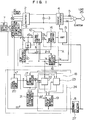
- Fig. 1 shows the construction of this embodiment.
- the current from a three-phase AC power supply 1 is converted by a rectifying circuit 2 into a DC current.
- the DC current is smoothed by a smoothing capacitor 3, and then converted by a reverse converter 4 into an arbitrary AC voltage of an arbitrary frequency.
- This AC voltage is supplied to a motor 6.
- a voltage type inverter is used for controlling the AC motor to change the revolution speed. That is, the reverse converter 4 is controlled by the logic section which is formed of a vector calculating portion A, a moment-of-inertia calculating portion B, a frequency acceleration or deceleration calculating portion 8 and a PWM waveform composer 14.
- a voltage controlling portion 12 outputs voltage commands Vd, Vq and an internal phase angle ⁇ on the basis of a frequency command f1* + f s , and currents id, iq. (For the operation of the vector calculating portion A, see Japanese Patent iaid-open Gazette No. 2-32788.)
- a coordinate converter 16 of the vector calculating portion A calculates a signal iq proportional to the output torque and a signal id proportional to the exciting current.
- the coordinate converter 16 makes d-q conversion from the following equation (4).
- the d-q coordinates are the rotating coordinates.
- ⁇ tan ⁇ 1 ⁇ -( ⁇ r ⁇ La ⁇ iq+r1 ⁇ id)/ (E1+r1 ⁇ iq+ ⁇ r ⁇ La ⁇ id) ⁇ (6)
- r1 is the primary resistor
- L a is the leakage reactance.
- the q-axis is in phase with the induced voltage E1
- iq is the signal proportional to the torque
- id is the signal proportional to the exciting current. Therefore, the output torque can be expressed by the value of iq.
- the primary voltage command V1 in Eq. (5) is supplied to the PWM waveform composer 14, and then fed through an amplifier 15 to a power switching element of the reverse converter 4.
- the frequency acceleration or deceleration calculating portion 8 functions to change the frequency command f1* at an arbitrary time and the rate of change of the frequency command f1* depending on the magnitude of the moment of inertia.
- the moment-of-inertia calculating portion B is formed of a torque current integrator 18, an accelerating end timing detector 17, a moment-of-inertia calculating portion 19, an accelerating signal generator 20 and a frequency change rate calculating portion 21.
- the moment-of-inertia calculator is operated at every certain time ⁇ t to execute the calculation.
- the accelerating signal generator 20 produces an accelerating signal a when the frequency is changed.
- the torque current integrator 18 starts operation when supplied with the accelerating signal a from the accelerating signal generator 20, and adds the torque proportional signal iq at every certain time ⁇ t.
- the accelerating end timing detector 17 monitors the torque proportional signal iq when supplied with the accelerating signal a from the accelerating signal generator 20. It detects the time when the torque proportional signal iq has decreased and reached a constant value, or when the motor has reached a constant speed. When the torque proportional signal iq becomes constant, the timing detector 17 supplies a signal b indicative of constant speed to the torque current integrator 18, thus stopping the adding operation.
- the moment-of-inertia calculating portion 19 calculates the equations (1) and (2) to find the moment of inertia GD2.
- a speed setting device 7 changes the frequency from f2 to f1
- the frequency/acceleration or deceleration calculating portion 8 increases the command frequency during the time t1.
- the motor starts to accelerate, and thus the load torque T L is added with the acceleration torque so that the output torque T0 is produced.
- the torque current integrator 18 integrates the current iq proportional to this output torque T0 relative to ⁇ t.
- the torque current detector 17 monitors the time when the torque current iq becomes constant (or only the load torque remains). This is because even if the output frequency of the inverter has reached f1, the motor does not reach the frequency.
- Fig. 4 shows the flowchart of the above operation. Use of software for this operation can be simply realized by the timer interruption of the flow shown in Fig. 4.
- step S1 When the timer interruption is started at intervals of ⁇ t, decision is made of whether the frequency command is changed or not (step S1).
- step S2 When the frequency command f1* is changed, the product of the torque current iq and ⁇ t is found (step S2).
- iq ⁇ t is found and added to the previous value to produce ⁇ iq ⁇ t (-S0-S1-S2-S0-).
- step S3 the torque current change is monitored (step S3, S4).
- step S3 the torque current change is monitored.
- step S4 the calculation of ⁇ iq ⁇ t at step S2 is continued (-S0-S1-S3-S4-S2-S0).
- step S5 When the torque current becomes constant, t2 is calculated (step S5) and the load torque iq cost ⁇ t2 is calculated (step S6).
- the moment of inertia is calculated from Eq. (10) by substituting ⁇ iq ⁇ t found at step S2 and iq cost ⁇ t2 found at step S6 into Eq. (10) (step S7).
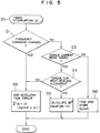
- Fig. 5 is a flowchart for this operation.
- ⁇ (iq ⁇ t - iq cost ⁇ t) is calculated. Therefore, in this embodiment, steps S5 and S6 in Fig. 4 can be omitted.
- the load torque proportional signal iq cost is found from the torque proportional signal at constant speed and stored at step S16.
- the frequency/acceleration or deceleration calculating portion 8 can decide the acceleration time for constant output torque T0 from Eq. (3) on the basis of the found GD2. This means that the motor can be accelerated or decelerated so that the primary current of the motor is a predetermined constant current value. If the output torque is not constant at this time, it is suggested that the moment of inertia of the load has changed. In this case, the acceleration or deceleration time is again set to a new value. Also, when the output torque is suddenly changed, it is decided that the load becomes abnormal, and the inverter can be stopped.
- An abnormality detecting circuit 27 shown in Fig. 1 detects a sudden change of the moment of inertia, and produces an abnormality signal AL. Moreover, the abnormality detecting circuit supplies the abnormality signal AL to the amplifying circuit 15, stopping the operation of the speed controller.
- the motor speed is supposed to become constant from the fact that the output torque proportional signal iq becomes constant
- the revolution speed of the motor can always be detected by use of a slip frequency calculating portion 10 shown in Fig. 1. Since the current iq proportional to the output torque is known, the slip frequency fs is calculated from the equation (11): where T2 is the secondary time constant, ⁇ 2 is the secondary magnetic flux, and M is the mutual inductance.
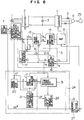
- Fig. 6 shows another embodiment. This embodiment is different from the embodiment of Fig. 1 in that a torque current integrator 31 and a moment-of-inertia calculating portion 26 have different constructions from those in the embodiment of Fig. 1.
- the torque current integrator 18 calculates the separate load torque component and output component and supplies them to the moment-of-inertia calculating portion 19, whereas in Fig. 6 the torque current integrator 31 calculates ⁇ (iq ⁇ t-iq cost ⁇ t) and supplies it to the moment-of-inertia calculating portion 26.
- the moment of inertia can be found without knowing the load torque T L .
- the moment-of-inertia calculating portion 30 calculates the moment of inertia GD2 from the equation (12) by substituting three pieces of information: the motor primary current i1 from the current detector 5, the amount of change of frequency ⁇ f from the frequency/acceleration or decelerating calculating portion 28 and the amount of change of time ⁇ t.
- the frequency is necessary to be changed twice as described above.
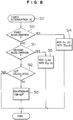
- Fig. 8 is a flowchart for the operation, and Fig.
- a voltage controlling portion 29 calculates and outputs an output voltage V on the basis of V/f ratio predetermined by a frequency command f*.
- the moment of inertia can be calculated.
- the speed or induced electromotive force feed-back is not necessary, and the moment of inertia can be calculated. That is, there is the effect that it can be realized to make the optimum accelerating and decelerating operation matched with the load.
- the control apparatus for the motor is simple in construction, highly reliable, economical, and very safe.
Landscapes
- Engineering & Computer Science (AREA)
- Power Engineering (AREA)
- Control Of Ac Motors In General (AREA)
- Control Of Electric Motors In General (AREA)
Applications Claiming Priority (2)
| Application Number | Priority Date | Filing Date | Title |
|---|---|---|---|
| JP250203/90 | 1990-09-21 | ||
| JP25020390A JP2892802B2 (ja) | 1990-09-21 | 1990-09-21 | 電動機の速度制御装置 |
Publications (2)
| Publication Number | Publication Date |
|---|---|
| EP0476588A1 true EP0476588A1 (de) | 1992-03-25 |
| EP0476588B1 EP0476588B1 (de) | 1996-06-26 |
Family
ID=17204357
Family Applications (1)
| Application Number | Title | Priority Date | Filing Date |
|---|---|---|---|
| EP91115754A Expired - Lifetime EP0476588B1 (de) | 1990-09-21 | 1991-09-17 | Verfahren und Vorrichtung zur Berechnung des Trägheitsmoments bei einem Motorgeschwindigkeitsregler und Verfahren und Vorrichtung zur Geschwindigkeitsregelung eines Motors |
Country Status (4)
| Country | Link |
|---|---|
| US (1) | US5175483A (de) |
| EP (1) | EP0476588B1 (de) |
| JP (1) | JP2892802B2 (de) |
| DE (1) | DE69120486T2 (de) |
Cited By (13)
| Publication number | Priority date | Publication date | Assignee | Title |
|---|---|---|---|---|
| EP0595560A1 (de) * | 1992-10-26 | 1994-05-04 | Plessey Semiconductors Limited | Geschwindigkeits-Steuereinrichtungen für Elektromotoren |
| EP0601432A3 (de) * | 1992-11-30 | 1994-12-28 | Meidensha Electric Mfg Co Ltd | Verfahren und System zur Abschätzung der Trägheitskräfte eines Zweimassensystems während der Geschwindigkeitsregelung. |
| EP0704689A2 (de) | 1994-09-30 | 1996-04-03 | AVL Gesellschaft für Verbrennungskraftmaschinen und Messtechnik mbH.Prof.Dr.Dr.h.c. Hans List | Verfahren zur Trägheitsmomentbestimmung |
| EP0791872A1 (de) * | 1996-02-27 | 1997-08-27 | Siemens Aktiengesellschaft | Einrichtung und Verfahren zur Überwachung von Kupplungen und/oder Riemengetrieben bei Achsen oder Spindeln an Werkzeugmaschinen, Robotern oder dergleichen |
| EP0798848A4 (de) * | 1995-09-22 | 1998-11-18 | Fanuc Ltd | Verfahren zur steuerung des stroms eines servomotor |
| EP0903845A3 (de) * | 1997-09-22 | 2001-07-11 | Matsushita Electric Industrial Co., Ltd. | Waschmaschine |
| EP2565465A1 (de) * | 2011-08-29 | 2013-03-06 | ABB Oy | Verfahren und Vorrichtung zur Bestimmung der Massenänderung eines Lüfterrads |
| CN104015631A (zh) * | 2014-06-02 | 2014-09-03 | 贾立进 | 一种电动汽车电驱动电子控制装置 |
| EP2852048A1 (de) * | 2013-09-19 | 2015-03-25 | Siemens Aktiengesellschaft | Elektrische Maschine mit adaptivem Regler |
| EP2690777A3 (de) * | 2012-07-25 | 2017-06-21 | Toshiba Schneider Inverter Corporation | Motorsteuervorrichtung |
| CN106986210A (zh) * | 2016-01-20 | 2017-07-28 | 佛克有限及两合公司 | 用于操作包装机的方法 |
| CN112919345A (zh) * | 2021-02-04 | 2021-06-08 | 三一汽车起重机械有限公司 | 一种起重机回转控制方法、装置、起重机及存储介质 |
| US11682993B1 (en) | 2022-05-06 | 2023-06-20 | Nxp Usa, Inc. | Apparatus and method for determining mechanical parameters of an electric motor and load |
Families Citing this family (19)
| Publication number | Priority date | Publication date | Assignee | Title |
|---|---|---|---|---|
| JP3084928B2 (ja) * | 1992-05-29 | 2000-09-04 | 三菱電機株式会社 | 電動機の位置制御装置 |
| JP3411310B2 (ja) * | 1992-09-09 | 2003-05-26 | 富士通株式会社 | モータ駆動回路及びその駆動方法 |
| US5440219A (en) * | 1993-05-21 | 1995-08-08 | Wilkerson; Alan W. | Induction motor speed control having improved sensing of motor operative conditions |
| DE69404927T2 (de) * | 1993-09-27 | 1998-03-19 | Matsushita Electric Works Ltd | Verfahren und Anordnung für Vektorsteuerung zum Steuern der Rotorgeschwindigkeit eines Induktionsmotor |
| KR100316280B1 (ko) * | 1995-03-10 | 2002-04-24 | 무라타 기카이 가부시키가이샤 | 스텝모터의제어방법 |
| GB2314427B (en) * | 1996-06-21 | 2000-10-18 | British Aerospace | Servomechanisms |
| JP3731060B2 (ja) * | 2000-11-14 | 2006-01-05 | 株式会社日立製作所 | イナーシャ演算方法及び電動機のドライブ装置 |
| DE10236847A1 (de) * | 2002-08-08 | 2004-02-26 | Dr. Johannes Heidenhain Gmbh | Verfahren zur Bestimmung des Massenträgheitsmomentes eines elektromotorischen Antriebssystems |
| US20040076498A1 (en) * | 2002-08-15 | 2004-04-22 | Thompson Patrick Kim | Device for towing a motorcycle using a tow truck and method therefor |
| US6920800B2 (en) * | 2003-08-15 | 2005-07-26 | Rockwell Automation Technologies, Inc. | Method for determining inertia of an electric motor and load |
| US7141946B2 (en) * | 2003-09-15 | 2006-11-28 | Rockwell Automation Technologies, Inc. | Method and apparatus for providing optimal acceleration feedback |
| US7622881B2 (en) * | 2007-02-28 | 2009-11-24 | Rockwell Automation Technologies, Inc. | Method and apparatus for estimating system inertia where number of motor rotations are restricted |
| CN102497151B (zh) * | 2011-12-30 | 2014-03-05 | 常州大学 | 一种智能重构柔性电机驱动控制器 |
| WO2014073053A1 (ja) * | 2012-11-07 | 2014-05-15 | パイオニア株式会社 | モータ制御装置及びモータ制御方法 |
| US8892291B2 (en) | 2013-03-12 | 2014-11-18 | Ford Global Technologies, Llc | Vehicle mass detection system |
| KR102103151B1 (ko) * | 2018-03-14 | 2020-04-22 | (주)아이티공간 | 구동부의 정밀 예지 보전방법 |
| KR102103146B1 (ko) * | 2018-03-14 | 2020-04-22 | (주)아이티공간 | 구동부의 정밀 예지 보전방법 |
| EP3891883B1 (de) | 2018-12-06 | 2025-03-19 | Sew-Eurodrive GmbH & Co. KG | Verfahren zum betreiben eines antriebsstranges und antriebsstrang |
| CN113979223B (zh) * | 2021-10-29 | 2023-04-07 | 广东韶钢松山股份有限公司 | 一种集卷托盘负载计算方法 |
Citations (1)
| Publication number | Priority date | Publication date | Assignee | Title |
|---|---|---|---|---|
| EP0262600A1 (de) * | 1986-09-29 | 1988-04-06 | Asea Ab | Verfahren und Vorrichtung zur optimalen Parameterregelung von Reglern, die rotierende und/oder lineare Bewegungen eines Industrieroboters steuern |
Family Cites Families (5)
| Publication number | Priority date | Publication date | Assignee | Title |
|---|---|---|---|---|
| CH503316A (de) * | 1969-02-06 | 1971-02-15 | Sulzer Ag | Stellantrieb |
| JPS59156191A (ja) * | 1983-02-23 | 1984-09-05 | Hitachi Ltd | 誘導電動機の制御方法 |
| JPS6188780A (ja) * | 1984-10-08 | 1986-05-07 | Hitachi Ltd | 速度制御装置の制御定数設定方法 |
| US4827197A (en) * | 1987-05-22 | 1989-05-02 | Beckman Instruments, Inc. | Method and apparatus for overspeed protection for high speed centrifuges |
| JP2585376B2 (ja) * | 1987-06-12 | 1997-02-26 | 株式会社日立製作所 | 誘導電動機の制御方法 |
-
1990
- 1990-09-21 JP JP25020390A patent/JP2892802B2/ja not_active Expired - Lifetime
-
1991
- 1991-09-17 DE DE69120486T patent/DE69120486T2/de not_active Expired - Lifetime
- 1991-09-17 EP EP91115754A patent/EP0476588B1/de not_active Expired - Lifetime
- 1991-09-20 US US07/763,144 patent/US5175483A/en not_active Expired - Lifetime
Patent Citations (1)
| Publication number | Priority date | Publication date | Assignee | Title |
|---|---|---|---|---|
| EP0262600A1 (de) * | 1986-09-29 | 1988-04-06 | Asea Ab | Verfahren und Vorrichtung zur optimalen Parameterregelung von Reglern, die rotierende und/oder lineare Bewegungen eines Industrieroboters steuern |
Non-Patent Citations (1)
| Title |
|---|
| PATENT ABSTRACTS OF JAPAN vol. 10, no. 263 (E-435)(2319) 9 September 1986 & JP-A-61 088 780 ( HITACHI LTD ) 7 May 1986 * |
Cited By (23)
| Publication number | Priority date | Publication date | Assignee | Title |
|---|---|---|---|---|
| EP0595560A1 (de) * | 1992-10-26 | 1994-05-04 | Plessey Semiconductors Limited | Geschwindigkeits-Steuereinrichtungen für Elektromotoren |
| GB2271893B (en) * | 1992-10-26 | 1996-10-30 | Plessey Semiconductors Ltd | Speed control arrangements for electric motors |
| EP0601432A3 (de) * | 1992-11-30 | 1994-12-28 | Meidensha Electric Mfg Co Ltd | Verfahren und System zur Abschätzung der Trägheitskräfte eines Zweimassensystems während der Geschwindigkeitsregelung. |
| US5477114A (en) * | 1992-11-30 | 1995-12-19 | Kabushiki Kaisha Meidensha | Method and system for estimating inertia of 2-mass system during speed control |
| EP0704689A2 (de) | 1994-09-30 | 1996-04-03 | AVL Gesellschaft für Verbrennungskraftmaschinen und Messtechnik mbH.Prof.Dr.Dr.h.c. Hans List | Verfahren zur Trägheitsmomentbestimmung |
| US5656768A (en) * | 1994-09-30 | 1997-08-12 | Avl Gesellschaft Fur Verbrennungskraftmaschinen Und Messtechnik M.B.H. Prof. Dr.H.C. Hans List | Method for determining the moment of inertia |
| EP0798848A4 (de) * | 1995-09-22 | 1998-11-18 | Fanuc Ltd | Verfahren zur steuerung des stroms eines servomotor |
| US5955863A (en) * | 1995-09-22 | 1999-09-21 | Fanuc Ltd. | Electric current control method for a servomotor |
| EP0791872A1 (de) * | 1996-02-27 | 1997-08-27 | Siemens Aktiengesellschaft | Einrichtung und Verfahren zur Überwachung von Kupplungen und/oder Riemengetrieben bei Achsen oder Spindeln an Werkzeugmaschinen, Robotern oder dergleichen |
| EP0903845A3 (de) * | 1997-09-22 | 2001-07-11 | Matsushita Electric Industrial Co., Ltd. | Waschmaschine |
| EP2565465A1 (de) * | 2011-08-29 | 2013-03-06 | ABB Oy | Verfahren und Vorrichtung zur Bestimmung der Massenänderung eines Lüfterrads |
| CN102966582A (zh) * | 2011-08-29 | 2013-03-13 | Abb公司 | 用于确定风机叶轮的质量变化的方法和设备 |
| US9021876B2 (en) | 2011-08-29 | 2015-05-05 | Abb Oy | Method and apparatus for determining change in mass of fan impeller |
| CN102966582B (zh) * | 2011-08-29 | 2015-09-30 | Abb技术有限公司 | 用于确定风机叶轮的质量变化的方法和设备 |
| EP2690777A3 (de) * | 2012-07-25 | 2017-06-21 | Toshiba Schneider Inverter Corporation | Motorsteuervorrichtung |
| EP2852048A1 (de) * | 2013-09-19 | 2015-03-25 | Siemens Aktiengesellschaft | Elektrische Maschine mit adaptivem Regler |
| CN104015631A (zh) * | 2014-06-02 | 2014-09-03 | 贾立进 | 一种电动汽车电驱动电子控制装置 |
| CN104015631B (zh) * | 2014-06-02 | 2019-04-16 | 贾立进 | 一种电动汽车电驱动电子控制装置 |
| CN106986210A (zh) * | 2016-01-20 | 2017-07-28 | 佛克有限及两合公司 | 用于操作包装机的方法 |
| EP3205612A3 (de) * | 2016-01-20 | 2017-12-20 | Focke & Co. (GmbH & Co. KG) | Verfahren zum betreiben einer verpackungsmaschine |
| CN112919345A (zh) * | 2021-02-04 | 2021-06-08 | 三一汽车起重机械有限公司 | 一种起重机回转控制方法、装置、起重机及存储介质 |
| CN112919345B (zh) * | 2021-02-04 | 2023-05-23 | 三一汽车起重机械有限公司 | 一种起重机回转控制方法、装置、起重机及存储介质 |
| US11682993B1 (en) | 2022-05-06 | 2023-06-20 | Nxp Usa, Inc. | Apparatus and method for determining mechanical parameters of an electric motor and load |
Also Published As
| Publication number | Publication date |
|---|---|
| JP2892802B2 (ja) | 1999-05-17 |
| EP0476588B1 (de) | 1996-06-26 |
| DE69120486D1 (de) | 1996-08-01 |
| DE69120486T2 (de) | 1996-10-31 |
| JPH04133689A (ja) | 1992-05-07 |
| US5175483A (en) | 1992-12-29 |
Similar Documents
| Publication | Publication Date | Title |
|---|---|---|
| EP0476588A1 (de) | Verfahren und Vorrichtung zur Berechnung des Trägheitsmoments bei einem Motorgeschwindigkeitsregler und Verfahren und Vorrichtung zur Geschwindigkeitsregelung eines Motors | |
| US6009003A (en) | Current/voltage control apparatus for elevator system | |
| US5583406A (en) | Control method and system for regeneration braking of an electric vehicle | |
| US4958117A (en) | Frequency control based on sensing voltage fed to an induction motor | |
| EP1796260B1 (de) | Vektorsteuerung eines asynchronmotors | |
| EP0330188B1 (de) | Flussvektorregelung für einen Asynchronmotor | |
| JP2708408B2 (ja) | 電圧制御形ベクトル制御インバータの制御装置 | |
| EP0165020B1 (de) | Leistungswandler für eine Wechselstromlast | |
| EP1729407A1 (de) | Steuerung eines permanentmagnet-synchronmotors | |
| EP0490024B1 (de) | Vektorsteuerung | |
| US4785225A (en) | Control apparatus for an induction motor | |
| US4625834A (en) | Speed control apparatus for elevator | |
| EP0536569A2 (de) | Steuergerät für Wechselstrommotor und Steuergerät für denselben verwendendes elektrisches rollendes Material | |
| US5270498A (en) | Elevator speed control apparatus with drive motor residual secondary magnetic flux control | |
| EP0526915B1 (de) | Regelsystem zur Geschwindigkeitsregelung eines elektrischen Motors | |
| US4671389A (en) | Speed control apparatus for an elevator | |
| EP0216373B1 (de) | Induktions-Motor/Generator-System | |
| JPH0410319B2 (de) | ||
| EP0616417B1 (de) | Regelungsverfahren für einen wechselstrommotor | |
| JP3817666B2 (ja) | 誘導電動機の駆動制御装置 | |
| JPH0197194A (ja) | 誘導電動機の速度制御装置 | |
| JP2847092B2 (ja) | ベクトル制御装置の自動調整方法 | |
| JPH01198292A (ja) | 誘導電動機の可変速制御装置 | |
| JP2528953B2 (ja) | 誘導電動機の速度制御装置 | |
| KR100339269B1 (ko) | 유도 전동기의 스톨 방지 장치 |
Legal Events
| Date | Code | Title | Description |
|---|---|---|---|
| PUAI | Public reference made under article 153(3) epc to a published international application that has entered the european phase |
Free format text: ORIGINAL CODE: 0009012 |
|
| AK | Designated contracting states |
Kind code of ref document: A1 Designated state(s): DE FR GB IT |
|
| 17P | Request for examination filed |
Effective date: 19920330 |
|
| 17Q | First examination report despatched |
Effective date: 19940112 |
|
| GRAH | Despatch of communication of intention to grant a patent |
Free format text: ORIGINAL CODE: EPIDOS IGRA |
|
| GRAH | Despatch of communication of intention to grant a patent |
Free format text: ORIGINAL CODE: EPIDOS IGRA |
|
| GRAA | (expected) grant |
Free format text: ORIGINAL CODE: 0009210 |
|
| AK | Designated contracting states |
Kind code of ref document: B1 Designated state(s): DE FR GB IT |
|
| REF | Corresponds to: |
Ref document number: 69120486 Country of ref document: DE Date of ref document: 19960801 |
|
| ET | Fr: translation filed | ||
| ITF | It: translation for a ep patent filed | ||
| PLBE | No opposition filed within time limit |
Free format text: ORIGINAL CODE: 0009261 |
|
| STAA | Information on the status of an ep patent application or granted ep patent |
Free format text: STATUS: NO OPPOSITION FILED WITHIN TIME LIMIT |
|
| 26N | No opposition filed | ||
| PGFP | Annual fee paid to national office [announced via postgrant information from national office to epo] |
Ref country code: FR Payment date: 20010717 Year of fee payment: 11 |
|
| REG | Reference to a national code |
Ref country code: GB Ref legal event code: IF02 |
|
| PG25 | Lapsed in a contracting state [announced via postgrant information from national office to epo] |
Ref country code: FR Free format text: LAPSE BECAUSE OF NON-PAYMENT OF DUE FEES Effective date: 20030603 |
|
| REG | Reference to a national code |
Ref country code: FR Ref legal event code: ST |
|
| PG25 | Lapsed in a contracting state [announced via postgrant information from national office to epo] |
Ref country code: IT Free format text: LAPSE BECAUSE OF NON-PAYMENT OF DUE FEES;WARNING: LAPSES OF ITALIAN PATENTS WITH EFFECTIVE DATE BEFORE 2007 MAY HAVE OCCURRED AT ANY TIME BEFORE 2007. THE CORRECT EFFECTIVE DATE MAY BE DIFFERENT FROM THE ONE RECORDED. Effective date: 20050917 |
|
| PGFP | Annual fee paid to national office [announced via postgrant information from national office to epo] |
Ref country code: GB Payment date: 20090824 Year of fee payment: 19 |
|
| PGFP | Annual fee paid to national office [announced via postgrant information from national office to epo] |
Ref country code: DE Payment date: 20090824 Year of fee payment: 19 |
|
| GBPC | Gb: european patent ceased through non-payment of renewal fee |
Effective date: 20100917 |
|
| REG | Reference to a national code |
Ref country code: DE Ref legal event code: R119 Ref document number: 69120486 Country of ref document: DE Effective date: 20110401 |
|
| PG25 | Lapsed in a contracting state [announced via postgrant information from national office to epo] |
Ref country code: DE Free format text: LAPSE BECAUSE OF NON-PAYMENT OF DUE FEES Effective date: 20110401 |
|
| PG25 | Lapsed in a contracting state [announced via postgrant information from national office to epo] |
Ref country code: GB Free format text: LAPSE BECAUSE OF NON-PAYMENT OF DUE FEES Effective date: 20100917 |