EP2565989A1 - Connecteur de dispositif et système de connecteur de dispositif - Google Patents
Connecteur de dispositif et système de connecteur de dispositif Download PDFInfo
- Publication number
- EP2565989A1 EP2565989A1 EP20120005039 EP12005039A EP2565989A1 EP 2565989 A1 EP2565989 A1 EP 2565989A1 EP 20120005039 EP20120005039 EP 20120005039 EP 12005039 A EP12005039 A EP 12005039A EP 2565989 A1 EP2565989 A1 EP 2565989A1
- Authority
- EP
- European Patent Office
- Prior art keywords
- bolt
- tightening
- connector
- mounting
- axial direction
- Prior art date
- Legal status (The legal status is an assumption and is not a legal conclusion. Google has not performed a legal analysis and makes no representation as to the accuracy of the status listed.)
- Withdrawn
Links
- 230000002093 peripheral effect Effects 0.000 claims abstract description 27
- 230000037431 insertion Effects 0.000 claims abstract description 23
- 238000003780 insertion Methods 0.000 claims abstract description 23
- 230000013011 mating Effects 0.000 claims description 8
- 238000007789 sealing Methods 0.000 claims description 5
- 239000004020 conductor Substances 0.000 claims description 4
- 229920005989 resin Polymers 0.000 claims description 3
- 239000011347 resin Substances 0.000 claims description 3
- 229910052751 metal Inorganic materials 0.000 description 7
- 239000002184 metal Substances 0.000 description 7
- 230000000717 retained effect Effects 0.000 description 4
- 239000012530 fluid Substances 0.000 description 3
- XLYOFNOQVPJJNP-UHFFFAOYSA-N water Substances O XLYOFNOQVPJJNP-UHFFFAOYSA-N 0.000 description 3
- 238000006073 displacement reaction Methods 0.000 description 2
- 229920003002 synthetic resin Polymers 0.000 description 2
- 239000000057 synthetic resin Substances 0.000 description 2
- 229910052782 aluminium Inorganic materials 0.000 description 1
- XAGFODPZIPBFFR-UHFFFAOYSA-N aluminium Chemical compound [Al] XAGFODPZIPBFFR-UHFFFAOYSA-N 0.000 description 1
- 238000002788 crimping Methods 0.000 description 1
- 230000001419 dependent effect Effects 0.000 description 1
Images


Classifications
-
- H—ELECTRICITY
- H01—ELECTRIC ELEMENTS
- H01R—ELECTRICALLY-CONDUCTIVE CONNECTIONS; STRUCTURAL ASSOCIATIONS OF A PLURALITY OF MUTUALLY-INSULATED ELECTRICAL CONNECTING ELEMENTS; COUPLING DEVICES; CURRENT COLLECTORS
- H01R13/00—Details of coupling devices of the kinds covered by groups H01R12/70 or H01R24/00 - H01R33/00
- H01R13/62—Means for facilitating engagement or disengagement of coupling parts or for holding them in engagement
- H01R13/621—Bolt, set screw or screw clamp
- H01R13/6215—Bolt, set screw or screw clamp using one or more bolts
-
- H—ELECTRICITY
- H01—ELECTRIC ELEMENTS
- H01R—ELECTRICALLY-CONDUCTIVE CONNECTIONS; STRUCTURAL ASSOCIATIONS OF A PLURALITY OF MUTUALLY-INSULATED ELECTRICAL CONNECTING ELEMENTS; COUPLING DEVICES; CURRENT COLLECTORS
- H01R13/00—Details of coupling devices of the kinds covered by groups H01R12/70 or H01R24/00 - H01R33/00
- H01R13/648—Protective earth or shield arrangements on coupling devices, e.g. anti-static shielding
- H01R13/658—High frequency shielding arrangements, e.g. against EMI [Electro-Magnetic Interference] or EMP [Electro-Magnetic Pulse]
- H01R13/6591—Specific features or arrangements of connection of shield to conductive members
- H01R13/6592—Specific features or arrangements of connection of shield to conductive members the conductive member being a shielded cable
-
- H—ELECTRICITY
- H01—ELECTRIC ELEMENTS
- H01R—ELECTRICALLY-CONDUCTIVE CONNECTIONS; STRUCTURAL ASSOCIATIONS OF A PLURALITY OF MUTUALLY-INSULATED ELECTRICAL CONNECTING ELEMENTS; COUPLING DEVICES; CURRENT COLLECTORS
- H01R13/00—Details of coupling devices of the kinds covered by groups H01R12/70 or H01R24/00 - H01R33/00
- H01R13/46—Bases; Cases
- H01R13/52—Dustproof, splashproof, drip-proof, waterproof, or flameproof cases
- H01R13/5219—Sealing means between coupling parts, e.g. interfacial seal
-
- H—ELECTRICITY
- H01—ELECTRIC ELEMENTS
- H01R—ELECTRICALLY-CONDUCTIVE CONNECTIONS; STRUCTURAL ASSOCIATIONS OF A PLURALITY OF MUTUALLY-INSULATED ELECTRICAL CONNECTING ELEMENTS; COUPLING DEVICES; CURRENT COLLECTORS
- H01R13/00—Details of coupling devices of the kinds covered by groups H01R12/70 or H01R24/00 - H01R33/00
- H01R13/648—Protective earth or shield arrangements on coupling devices, e.g. anti-static shielding
- H01R13/658—High frequency shielding arrangements, e.g. against EMI [Electro-Magnetic Interference] or EMP [Electro-Magnetic Pulse]
- H01R13/6598—Shield material
Definitions
- the present invention relates to a device connector to be mounted and fixed to a device and to a device connector system.
- a bolt cap for protecting a tightening portion of a bolt is known, for example, from Japanese Unexamined Patent Publication No. H08-111217 .
- This bolt cap is formed to collectively cover a stud bolt standing on a battery, a terminal fitting connected to this stud bolt and a fastening nut to be threadably engaged with the stud bolt and bolting the terminal fitting.
- the terminal fitting includes a connecting portion in the form of a circular hole into which the stud bolt is inserted and a crimping portion laterally extending from this connecting portion and to be crimped and connected to an end of a wire.
- the bolt cap laterally extends in conformity with the shape of the terminal fitting, it is formed to cover not only the bolted part, but the entire terminal fitting. As a result, the bolt cap and the terminal fitting come into contact in a turning direction about the tightening portion of the bolt, whereby the rotation of the bolt cap is prevented.
- the present invention was completed in view of the above situation and an object thereof is to enable a bolt cap to be held without increasing the number of parts.
- a device connector to be mounted and fixed to a device by means of a bolt including a tightening portion to be tightened using a tool in screwing the bolt into a bolt hole provided in the device in an axial direction of the bolt hole
- the device connector comprising: a connector main body including an insertion hole into which the bolt at least partly is insertable in the axial direction; a bolt cap to be mounted to at least partly cover the tightening portion of the bolt; a seating portion provided at a part of the connector main body adjacent to the insertion hole to be sandwiched by a hole edge part of the bolt hole and the tightening portion of the bolt in the axial direction; a mounting recess being formed between the seating portion and a bolt flange projecting from an outer peripheral side surface of the tightening portion of the bolt in a direction crossing the axial direction; and a mounting portion to be mounted in the mounting recess and engaged with the bolt cap in the axial direction, thereby holding the bolt cap in a state at
- the bolt cap is to be engaged with the mounting portion in the axial direction when the mounting portion is mounted into the mounting recess and the bolt cap can be mounted to at least partly cover the tightening portion of the bolt, whereby the bolt cap is held in the state covering the tightening portion of the bolt.
- This can prevent an operation of separating two connectors from being unduly performed by turning the tightening portion using a tool.
- the mounting recess is formed between the seating portion and the bolt flange, it is not necessary to form the mounting recess separately from the bolt and the bolt cap.
- the bolt cap can be held without increasing the number of parts.
- the bolt cap and the mounting portion are connected via at least one flexible hinge.
- the bolt is to be rotatably supported in the seating portion by mounting a holding member, particularly comprising a C-ring, on a shaft portion at least partly inserted through the insertion hole.
- the connector main body includes a housing made of resin and a shield shell made of a conductive material and substantially covering the housing, and the seating portion is provided on the shield shell.
- the mounting portion includes at least one engaging portion and the seating portion includes at least one engageable portion which is engaged with the engaging portion to prevent the rotation of the mounting portion.
- a resilient member is to be mounted on the outer peripheral surface of the connector main body to be held in close contact with the connector main body and a portion of a mating connector in a state where the device connector is properly connected to the mating connector in order to provide fluid-tight sealing is provided between the connector main body and a mating housing of the mating connector.
- a device connection system comprising: a device connector according to the above aspect of the invention or a particular embodiment thereof to be mounted and fixed to a device, and a bolt including a tightening portion to be tightened using a tool in screwing the bolt into a bolt hole provided in the device in an axial direction of the bolt hole.
- a device connector system comprising a bolt including a tightening portion to be tightened using a tool in screwing the bolt into a bolt hole provided in the device in an axial direction of the bolt hole; a connector main body including an insertion hole into which the bolt is insertable in the axial direction; a bolt cap to be mounted to cover the tightening portion of the bolt; a seating portion provided at a part of the connector main body around the insertion hole to be sandwiched by a hole edge part of the bolt hole and the tightening portion of the bolt in the axial direction; a bolt flange projecting from an outer peripheral side surface of the tightening portion of the bolt in a direction crossing the axial direction, a mounting recess being formed between the bolt flange and the seating portion; and a mounting portion to be mounted in the mounting recess and engaged with the bolt cap in the axial direction, thereby holding the bolt cap in a state covering the tightening portion of the bolt.
- the bolt cap is engaged with the mounting portion in the axial direction when the mounting portion is mounted into the mounting recess and the bolt cap is mounted to cover the tightening portion of the bolt, whereby the bolt cap is held in the state covering the tightening portion of the bolt.
- This can prevent an operation of separating two connectors from being unduly performed by turning the tightening portion using a tool.
- the mounting recess is formed between the seating portion and the bolt flange, it is not necessary to form the mounting recess separately from the bolt and the bolt cap.
- the bolt cap can be held without increasing the number of parts.
- the above aspect(s) of present invention may be preferably embodied to have the following configurations.
- the bolt cap and the mounting portion may be connected via at least one flexible hinge.
- the bolt may be rotatably supported in the seating portion by mounting a holding member such as C-ring on a shaft portion inserted through the insertion hole.
- the shaft portion of the bolt may be rotatably supported in the seating portion by inserting the shaft portion of the bolt into the insertion hole and mounting the holding member (particularly the C-ring) on the shaft portion of the bolt.
- the connector main body may include a housing made of resin and a shield shell made of a conductive material such as metal and at least partly covering the housing, and the seating portion may be provided on the shield shell.
- the shield shell can be shield-connected to the device by tightening the bolt with the shield shell held in contact with the device.
- the mounting portion may include an engaging portion and the seating portion may include an engageable portion which is engaged with the engaging portion to prevent the rotation of the mounting portion.
- the rotation of the mounting portion relative to the seating portion can be prevented by engaging the engaging portion of the mounting portion with the engageable portion of the seating portion.
- the tightening portion may comprise a head portion, a bolt flange connected at a shaft portion side of this head portion and a small diameter portion connected at the shaft portion side of this bolt flange, wherein the bolt flange particularly may have a diameter larger than the head portion and/or the small diameter portion.
- the head portion substantially may be in the form of a column having a substantially right hexagonal cross-section and/or the bolt flange and the small diameter portion may both have a right circular cross-sectional shape.
- a clearance may be set between a front surface of the bolt flange and a rear surface of the seating portion and the mounting recess may be formed by a wall surface forming this clearance.
- a particular embodiment of the present invention is described with reference to FIGS. 1 to 10 .
- a male connector 10 according to this embodiment is connectable to a female connector 50 fixed to a case C of a device by tightening a tightening bolt B into the case C of the device as shown in FIG. 3 .
- two-pole male connector 10 and female connector 50 are illustrated.
- the invention is also applicable to any other type of connector such as a one-pole connector, or a plural-pole connector, irrespective of whether it is a male or a female connector.
- forward and backward directions FBD are based on a connecting direction CD of the two connectors 10, 50 and sides of the two connectors 10, 50 to be connected are referred to as front sides.
- an "axial direction" AD of the present invention particularly corresponds to forward and backward directions FBD of this embodiment.
- the case C of the device particularly is made of an electrically conductive metal.
- a mounting hole C1 is provided in the case C of the device, and the female connector 50 is to be at least partly fitted into this mounting hole C1.
- One or more, particularly a pair of holes are provided at a peripheral edge part of the mounting hole C1 in the case C of the device.
- one hole is a fixing hole (not shown) into which a fixing bolt (not shown) for fixing the female connector 50 to the case C of the device is screwed, and/or one hole (particularly the other hole) is a bolt hole C2 into which the tightening bolt B is screwed to connect the male connector 10 and the female connector 50.
- the female connector 50 includes a female housing 51 made e.g. of synthetic resin and at least one female terminal 52 (particularly substantially in the form of a rectangular or polygonal tube) is to be at least partly accommodated in this female connector 51.
- the female terminal 52 is to be connected to an inner wiring (not shown) of the device.
- the female housing 51 is shaped to be long in a width direction and internally provided with a female cavity 53 for at least partly accommodating the female terminal 52.
- a fixing flange 54 laterally or radially projects from an outer peripheral side surface of the female housing 51 as shown in FIG. 4 .
- a conductive (particularly metal) collar 55 is integrally or unitarily formed to this fixing flange 54.
- a part of the female connector 50 behind the fixing flange 54 serves as a device-side fitting portion 50A to be at least partly fitted into the mounting hole C1 of the case C of the device.
- a part of the female connector 50 before the fixing flange 54 serves as a male-side fitting portion 50B projecting from the outer surface of the case C of the device to be at least partly fitted into the male connector 10.
- a first resilient (particularly rubber) ring or seal 56A is to be mounted on the outer peripheral surface of the device-side fitting portion 50A and this first resilient (rubber) ring or seal 56A is to be held in close contact with the outer peripheral surface of the device-side fitting portion 50A and the inner peripheral surface of the mounting hole C1. In this way, fluid- or liquid-tight sealing is provided between the case C of the device and the device-side fitting portion 50A, thereby preventing fluid (particularly water) entrance into the interior of the case C of the device.
- a second resilient (particularly rubber) ring or seal 56B is to be mounted on the outer peripheral surface of the male-side fitting portion 50B and to be held in close contact with the outer peripheral surface of the male-side fitting portion 50B and the inner peripheral surface of a shield shell 20 to be described later.
- fluid- or liquid-tight sealing is provided between the male-side fitting portion 508 and the shield shell 20, thereby preventing fluid (e.g. water) entrance into the interior of the shield shell 20.
- the male connector 10 includes a male housing 11 made e.g. of synthetic resin and at least one male terminal 12 is to be at least partly accommodated in this male housing 11.
- the male housing 11 particularly is shaped to be long in the width direction and internally provided with a terminal holding portion 13 in which the male terminal 12 at least partly is mounted, particularly press-fitted and held.
- the male terminal 12 is to be connected to an end of a (particularly shielded) wire W and electrically conductively connected to the female terminal 52 as the one or more, e.g. two connectors 10, 50 are connected.
- a third resilient (particularly rubber) ring 14 is to be mounted on the outer peripheral surface of the male housing 11. As shown in FIG. 3 , this third resilient (rubber) ring 14 is to be held in close contact with the outer peripheral surface of the male housing 11 and the inner peripheral surface of the male-side fitting portion 50B in a state where the two connectors 10, 50 are properly connected. In this way, fluid- or liquid-tight sealing is provided between the male housing 11 and the female housing 51, thereby preventing fluid (particularly water) entrance into the interior of the female housing 51.
- the male housing 11 is to be covered by the (particularly substantially tubular) shield shell 20.
- This shield shell 20 is made of an electrically conductive material such as metal and, specifically, made of aluminum die-cast.
- a seating portion 21 projecting radially outwardly is provided at the front end opening edge of the shield shell 20.
- An insertion hole 22 is formed to penetrate through the seating portion 21 in a plate thickness direction TD, and the tightening bolt B is to be at least partly inserted into this insertion hole 22.
- the tightening bolt B is provided with a groove in which a holding member, such as a C-ring 23, is to be mounted, and the tightening bolt B is retained and rotatably supported in the seating portion 21 by mounting the holding member (particularly the C-ring 23) on the tightening bolt B inserted into the insertion hole 22.
- a holding member such as a C-ring 23
- a mounting flange 15 is provided on the outer peripheral surface of the male housing 11. This mounting flange 15 is located at a fixed or specified (predetermined or predeterminable) depth position in the shield shell 20 of the male housing 11 particularly by coming into contact with at least one step 24 provided in the shield shell 20. Further, the mounting flange 15 includes one or more, particularly a pair of mounting pieces 16, 16 particularly substantially extending backward. Contrary to this, one or more, particularly a pair of mounting projections 25, 25 engageable with the (particularly both) mounting piece(s) 16, 16 are provided in or at the shield shell 20. By the engagement of the (particularly both) mounting piece(s) 16, 16 with the (particularly both) mounting projection(s) 25, 25, the male housing 11 is held and retained in or on or with respect to the shield shell 20.
- the tightening bolt B includes a tightening portion B1 arranged at one end side thereof and a substantially cylindrical shaft portion B2.
- the shaft portion B2 extends in the axial direction AD from an axial center part of the tightening portion B1.
- a part of the shaft portion B2 to be at least partly accommodated in the insertion hole 22 particularly is not formed with an external thread on the outer peripheral surface as shown in FIG. 2
- a leading end side of the shaft portion B2 before the C-ring 23 particularly is formed with an external thread on the outer peripheral surface.
- the tightening portion B1 is composed of or comprises a head portion B11 as a main portion, a bolt flange B12 connected at the shaft portion B2 side of this head portion B11 and a small diameter portion B13 connected at the shaft portion B2 side of this bolt flange B12.
- the bolt flange B12 particularly has a diameter larger than the head portion B11 and/or the small diameter portion B13.
- the head portion B11 particularly is in the form of a column having a substantially right hexagonal cross-section.
- the bolt flange B12 and the small diameter portion B13 particularly both have a right circular cross-sectional shape as shown in FIGS. 8 and 9 .
- a clearance S particularly is set between the outer peripheral surface of the bolt flange B12 and the inner peripheral surface of a mounting portion 42 to be described later as shown in FIG. 8 .
- the tightening portion B1 is arranged behind the seating portion 21.
- the front surface of the small diameter portion B13 pushes the rear surface of the seating portion 21 forward (i.e. in connecting direction CD) by tightening the tightening bolt B into the bolt hole C2, thereby bringing the two connectors 10, 20 into a properly connected state.
- a clearance particularly is set between the front surface of the bolt flange B12 and the rear surface of the seating portion 21 and a mounting recess D is formed by a wall surface forming this clearance. That is, the mounting recess D particularly is formed by the bolt flange B12, the small diameter portion B13 and a rear hole edge part of the insertion hole 22.
- a bolt cap 40 is mountable on the tightening portion B1.
- the bolt cap 40 particularly is connected to the mounting portion 42 via at least one flexible hinge 41.
- the mounting portion 42 is to be mounted in the mounting recess D.
- the mounting portion 42 includes a mounting projection 43 to be at least partly fitted into the mounting recess D and a dimension of this mounting projection 43 particularly is set to be shorter than a dimension of the mounting recess D in forward and backward directions FBD.
- the mounting projection 43 at least partly is to be fitted into the mounting recess D and engaged therewith in forward and backward directions FBD in this way, whereby the mounting portion 42 is held and retained in the mounting recess D.
- the mounting portion 42 is formed with one or more, particularly a plurality of engaging projections 44.
- one or more, particularly a plurality of engaging recesses 26 for preventing the displacement or rotation of the mounting portion 42 by being engaged with the respective engaging projection(s) 44 are provided in a part of the seating portion 21 substantially facing the mounting portion 42.
- Inner peripheral wall(s) of the engaging re-cesse(s) 26 come into contact with outer peripheral wall(s) of the engaging projection(s) 44 in a turning direction about an axis center of the insertion hole 22. In this way, the mounting portion 42 is held in the mounting recess D with the displacement or rotation thereof prevented.
- the one or more engaging projections 44 particularly substantially are in the form of columns having a circular cross-section and the one or more engaging recesses 26 particularly substantially are in the form of circular holes having a circular cross-section.
- a total of three engaging projections 44 and a total of three engaging recesses 26 substantially are arranged, both on a concentric circle centered on the axis center of the shaft portion B2.
- a pair of the engaging projection 44 and the engaging recess 26 are arranged at each of substantially opposite sides of the shaft portion B2 in a projecting direction of the mounting portion 42.
- the bolt cap 40 is or can be positioned in a normal mounting posture (posture in which the bolt cap 40 is arranged at the shown left side of the shaft portion B2 in FIG. 10 ).
- a normal mounting posture possibly in which the bolt cap 40 is arranged at the shown left side of the shaft portion B2 in FIG. 10 .
- the mounting of the bolt cap 40 in an opposite posture particularly is prevented and a space for bolt tightening using a tightening tool such as an impact wrench is secured at the shown right side of the shaft portion B2.
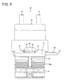
- the bolt cap 40 includes one or more, particularly a plurality of locking portions engageable with the mounting portion 42. Out of these locking portions, a pair of first locking portions 45, 45 arranged on the hinge 41 side are engageable with a first engaging portion 46 provided on the mounting portion 42 from a radially outer side as shown in FIG. 6 . Further, out of the plurality of locking portions, a second locking portion 47 arranged at a position facing the hinge 41 is composed of or comprises a pair of second locking pieces 47A, 47A as shown in FIG. 7 . These second locking pieces 47A, 47A are engageable with a pair of second engaging portions 48, 48 provided on the mounting portion 42 from an inner side in the turning direction.
- the respective locking portions 45, 47 are both resiliently deformably provided, are resiliently deformed to move onto the corresponding engaging portions 46, 48 while the bolt cap 40 is being mounted to cover the tightening portion B1, and are resiliently at least partly restored when the bolt cap 40 is properly mounted on the tightening portion B1.
- the both locking portions 45, 47 are locking pieces used to fix the bolt cap 40 to the mounting portion 42. If it is tried to fix the bolt cap 40 to the mounting portion 42 only by the second locking portion 47, a part of the mounting portion 42 near the hinge 41 may be lifted from the mounting portion 42 due to the rigidity (resilient restoring force) of the hinge 41.
- the both first locking portions 45, 45 are provided to prevent such a lifting movement.
- the male housing 11 is lightly fitted into the female housing 51 (e.g. by the hands) in connecting the male connector 10 to the female connector 50.
- the two connectors 10, 50 are gradually connected (or their connection is assisted) by tightening the tightening bolt B into the bolt hole C2. Since the mounting portion 42 is retained in the mounting recess D in the axial direction AD and the turning direction, the rotation of the mounting portion 42 together with the tightening bolt B can be prevented.
- the bolt cap 40 is mounted to at least partly cover the tightening portion B1. This can prevent the tightening portion B1 from being turned using a tool to separate the two connectors 10, 50.
- the bolt cap 40 can be held without increasing the number of parts.
- the bolt cap 40 particularly is locked in the axial direction AD with respect to the mounting portion 42 when the mounting portion 42 is mounted in the mounting recess D and the bolt cap 40 is mounted to at least partly cover the tightening portion B1 of the tightening bolt B, whereby the bolt cap 40 can be held in a state at least partly covering the tightening portion B1 of the tightening bolt b.
- the mounting recess D is formed between the seating portion 21 and the bolt flange B12, it is not necessary to form the mounting recess D separately from the tightening bolt B and the bolt cap 40.
- the bolt cap 40 can be held without increasing the number of parts.
- the bolt cap 40 and the mounting portion 42 particularly can be handled as an integral part by the presence of the at least one hinge 41 even if the bolt cap 40 is removed from the tightening portion B1 of the tightening bolt B, there is no possibility of losing the bolt cap 40.
- the shaft portion B2 of the tightening bolt B can be rotatably supported in the seating portion 21 by inserting the shaft portion B2 of the tightening bolt B into the insertion hole 22 and mounting the holding member (particularly the C-ring 23) on the shaft portion B2 of the tightening bolt B.
- the engaging projections 44 of the mounting portion 42 particularly are engaged with the engaging recesses 26 of the seating portion 21, whereby the rotation of the mounting portion 42 relative to the seating portion 21 can be prevented.
- the male connector 10 includes a tightening bolt B including a tightening portion B1 to be tightened using a tool in screwing the tightening bolt into a bolt hole C2 in an axial direction of the bolt hole C2, a shield shell 20 including an insertion hole 22 into which the tightening bolt B at least partly is insertable in the axial direction, a bolt cap 40 to be mounted to at least partly cover the tightening portion B1, a seating portion 21 provided at a part of the shield shell 20 adjacent or around or close to the insertion hole 22 to be sandwiched by a hole edge part of the bolt hole C2 and the tightening portion B1 in the axial direction AD, a bolt flange B12 projecting from an outer peripheral side surface of the tightening portion B1 in a direction crossing the axial direction AD, a mounting recess D being formed between the bolt f
Landscapes
- Connector Housings Or Holding Contact Members (AREA)
- Details Of Connecting Devices For Male And Female Coupling (AREA)
Applications Claiming Priority (1)
| Application Number | Priority Date | Filing Date | Title |
|---|---|---|---|
| JP2011192586A JP5733573B2 (ja) | 2011-09-05 | 2011-09-05 | 機器用コネクタ |
Publications (1)
| Publication Number | Publication Date |
|---|---|
| EP2565989A1 true EP2565989A1 (fr) | 2013-03-06 |
Family
ID=46796189
Family Applications (1)
| Application Number | Title | Priority Date | Filing Date |
|---|---|---|---|
| EP20120005039 Withdrawn EP2565989A1 (fr) | 2011-09-05 | 2012-07-06 | Connecteur de dispositif et système de connecteur de dispositif |
Country Status (4)
| Country | Link |
|---|---|
| US (1) | US8662920B2 (fr) |
| EP (1) | EP2565989A1 (fr) |
| JP (1) | JP5733573B2 (fr) |
| CN (1) | CN102983468B (fr) |
Cited By (2)
| Publication number | Priority date | Publication date | Assignee | Title |
|---|---|---|---|---|
| WO2018127512A1 (fr) * | 2017-01-06 | 2018-07-12 | Sibas Electronics (Xiamen) Co., Ltd | Dispositif de verrouillage et raccord |
| CN118572441A (zh) * | 2024-07-31 | 2024-08-30 | 深圳市华银兴业科技有限公司 | 一种耐用的连接线 |
Families Citing this family (22)
| Publication number | Priority date | Publication date | Assignee | Title |
|---|---|---|---|---|
| JP5751875B2 (ja) * | 2011-03-22 | 2015-07-22 | 矢崎総業株式会社 | シールドコネクタ |
| JP5733573B2 (ja) * | 2011-09-05 | 2015-06-10 | 住友電装株式会社 | 機器用コネクタ |
| JP5973957B2 (ja) * | 2013-06-07 | 2016-08-23 | 本田技研工業株式会社 | 接続ユニット |
| JP5847132B2 (ja) * | 2013-07-09 | 2016-01-20 | 古河電気工業株式会社 | 締結部材被覆構造 |
| JP6335075B2 (ja) * | 2014-09-05 | 2018-05-30 | タイコエレクトロニクスジャパン合同会社 | コネクタ |
| JP5922271B1 (ja) * | 2015-02-12 | 2016-05-24 | 住友電装株式会社 | 電線挿通部材 |
| JP6401736B2 (ja) * | 2016-05-20 | 2018-10-10 | 矢崎総業株式会社 | コネクタ |
| DE102016118163A1 (de) * | 2016-09-26 | 2018-03-29 | Rausch & Pausch Gmbh | Lösbare verbindungseinrichtung für hohe ströme |
| JP6744578B2 (ja) | 2017-01-26 | 2020-08-19 | 住友電装株式会社 | カバー部材及び機器用コネクタ |
| JP6709754B2 (ja) * | 2017-05-31 | 2020-06-17 | 矢崎総業株式会社 | コネクタハウジングの取付構造 |
| US10116078B1 (en) * | 2017-08-01 | 2018-10-30 | Delphi Technologies, Inc. | High current compression blade connection system |
| JP6907900B2 (ja) * | 2017-11-22 | 2021-07-21 | 住友電装株式会社 | 機器用コネクタ |
| JP6928994B2 (ja) * | 2017-11-30 | 2021-09-01 | タイコエレクトロニクスジャパン合同会社 | キャップ |
| JP6670817B2 (ja) * | 2017-12-20 | 2020-03-25 | 矢崎総業株式会社 | コネクタ及びコネクタ付き電線 |
| JP2020102307A (ja) * | 2018-12-20 | 2020-07-02 | 矢崎総業株式会社 | コネクタ |
| JP2020202036A (ja) * | 2019-06-06 | 2020-12-17 | 株式会社オートネットワーク技術研究所 | シールドコネクタ |
| JP7055783B2 (ja) * | 2019-10-17 | 2022-04-18 | 矢崎総業株式会社 | 嵌合コネクタ |
| JP1677818S (ja) * | 2020-08-27 | 2021-01-25 | 電気コネクタ用ハウジング | |
| JP1677817S (ja) * | 2020-08-27 | 2021-01-25 | 電気コネクタ | |
| JP7597768B2 (ja) * | 2022-09-14 | 2024-12-10 | 矢崎総業株式会社 | コネクタ |
| JP2025012873A (ja) * | 2023-07-14 | 2025-01-24 | 住友電装株式会社 | コネクタ |
| JP2025167156A (ja) * | 2024-04-25 | 2025-11-07 | 住友電装株式会社 | コネクタ及びコネクタアセンブリ |
Citations (6)
| Publication number | Priority date | Publication date | Assignee | Title |
|---|---|---|---|---|
| US3740981A (en) * | 1971-04-27 | 1973-06-26 | Hudson Lock Inc | Closure device for locks |
| JPH08111217A (ja) | 1994-10-11 | 1996-04-30 | Honda Motor Co Ltd | 自動車用電池の出力端子構造及びそれに接続する配線コードの接続構造 |
| GB2297000A (en) * | 1995-01-11 | 1996-07-17 | Gore & Ass | Clutching mechanism of connector or fastener |
| EP2190074A1 (fr) * | 2007-09-03 | 2010-05-26 | Sumitomo Wiring Systems, Ltd. | Dispositif de prévention contre l'extraction pour un connecteur |
| US20110053434A1 (en) * | 2008-02-13 | 2011-03-03 | Hans-Peter Seng | Retaining device for cable lugs |
| JP2011086461A (ja) * | 2009-10-14 | 2011-04-28 | Sumitomo Wiring Syst Ltd | シールドコネクタ |
Family Cites Families (38)
| Publication number | Priority date | Publication date | Assignee | Title |
|---|---|---|---|---|
| JP2967164B2 (ja) * | 1995-05-25 | 1999-10-25 | 品川商工株式会社 | ネジ頭部キャップ |
| JPH10184633A (ja) * | 1996-12-24 | 1998-07-14 | Aoyama Seisakusho Co Ltd | ボルト |
| JP3627209B2 (ja) * | 1999-04-07 | 2005-03-09 | 矢崎総業株式会社 | シールドコネクタ構造 |
| DE60133787T2 (de) * | 2000-03-07 | 2009-06-25 | AutoNetworks Technologies, Ltd., Nagoya | Abgeschirmter Verbinder und Anschlusskontaktanordnung für elektrisches abgeschirmtes Kabel |
| FR2807219B1 (fr) * | 2000-03-31 | 2004-04-02 | Labinal | Dispositif de connexion electrique et dispositif de distribution de puissance le comportant |
| JP2002075557A (ja) * | 2000-06-12 | 2002-03-15 | Auto Network Gijutsu Kenkyusho:Kk | シールドコネクタ |
| JP2002313453A (ja) * | 2001-04-18 | 2002-10-25 | Yazaki Corp | 機器直付け用シールドコネクタ |
| JP2002324627A (ja) * | 2001-04-25 | 2002-11-08 | Yazaki Corp | 電磁波シールド構造 |
| JP2003323932A (ja) * | 2002-05-01 | 2003-11-14 | Yazaki Corp | シールドコネクタ |
| TW549740U (en) * | 2002-07-26 | 2003-08-21 | Hon Hai Prec Ind Co Ltd | Electrical connector |
| US6921292B2 (en) * | 2002-11-21 | 2005-07-26 | Autonetworks Technologies, Ltd. | Connector having shielding shell |
| JP2005019188A (ja) * | 2003-06-26 | 2005-01-20 | Auto Network Gijutsu Kenkyusho:Kk | 機器用コネクタ |
| JP4007975B2 (ja) * | 2004-06-21 | 2007-11-14 | 日本航空電子工業株式会社 | コネクタ |
| JP4650691B2 (ja) * | 2006-03-03 | 2011-03-16 | 住友電装株式会社 | 電気接続構造 |
| US7494374B2 (en) * | 2007-02-01 | 2009-02-24 | Tyco Electronics Corporation | Panel mount electrical connector |
| DE112008000565T5 (de) * | 2007-03-02 | 2010-01-07 | AUTONETWORKS Technologies, LTD., Yokkaichi | Abschirmschale |
| US7393218B1 (en) * | 2007-03-19 | 2008-07-01 | Lear Corporation | Connector assembly with overmolded shielded housing |
| CA2684934A1 (fr) * | 2007-05-23 | 2008-11-27 | Tm4 Inc. | Connecteur electrique |
| JP4632320B2 (ja) * | 2007-11-09 | 2011-02-16 | 住友電装株式会社 | 機器用コネクタ |
| JP5095446B2 (ja) * | 2008-03-05 | 2012-12-12 | 矢崎総業株式会社 | コネクタ |
| JP5046043B2 (ja) * | 2008-07-10 | 2012-10-10 | 住友電装株式会社 | コネクタ |
| US7878844B2 (en) * | 2009-01-08 | 2011-02-01 | Tyco Electronics Corporation | Panel connector assembly |
| JP2010244975A (ja) * | 2009-04-09 | 2010-10-28 | Sumitomo Wiring Syst Ltd | コネクタ |
| JP5417954B2 (ja) * | 2009-04-09 | 2014-02-19 | 住友電装株式会社 | 防水コネクタ |
| JP5240522B2 (ja) * | 2009-04-13 | 2013-07-17 | 住友電装株式会社 | コネクタ |
| JP5338562B2 (ja) * | 2009-08-21 | 2013-11-13 | 住友電装株式会社 | シールドコネクタ及びワイヤハーネス |
| JP2011048949A (ja) * | 2009-08-25 | 2011-03-10 | Sumitomo Wiring Syst Ltd | シールドコネクタ装置 |
| JP2011048945A (ja) * | 2009-08-25 | 2011-03-10 | Sumitomo Wiring Syst Ltd | コネクタ |
| JP5375440B2 (ja) * | 2009-08-26 | 2013-12-25 | 住友電装株式会社 | 雄型コネクタ及びコネクタ装置 |
| JP5251840B2 (ja) * | 2009-11-17 | 2013-07-31 | 住友電装株式会社 | 機器用コネクタ |
| JP5467850B2 (ja) * | 2009-12-03 | 2014-04-09 | 矢崎総業株式会社 | L字型コネクタ |
| JP5485731B2 (ja) * | 2010-02-02 | 2014-05-07 | 矢崎総業株式会社 | 防水型シールドコネクタ |
| JP5531935B2 (ja) * | 2010-12-03 | 2014-06-25 | 住友電装株式会社 | コネクタ |
| JP5531940B2 (ja) * | 2010-12-13 | 2014-06-25 | 住友電装株式会社 | 防水コネクタ |
| JP5626047B2 (ja) * | 2011-03-15 | 2014-11-19 | 住友電装株式会社 | 機器用コネクタ |
| JP5640837B2 (ja) * | 2011-03-15 | 2014-12-17 | 住友電装株式会社 | 機器用コネクタ |
| JP5861289B2 (ja) * | 2011-07-13 | 2016-02-16 | 住友電装株式会社 | コネクタ |
| JP5733573B2 (ja) * | 2011-09-05 | 2015-06-10 | 住友電装株式会社 | 機器用コネクタ |
-
2011
- 2011-09-05 JP JP2011192586A patent/JP5733573B2/ja active Active
-
2012
- 2012-07-06 EP EP20120005039 patent/EP2565989A1/fr not_active Withdrawn
- 2012-08-10 US US13/571,436 patent/US8662920B2/en active Active
- 2012-08-28 CN CN201210310484.0A patent/CN102983468B/zh active Active
Patent Citations (6)
| Publication number | Priority date | Publication date | Assignee | Title |
|---|---|---|---|---|
| US3740981A (en) * | 1971-04-27 | 1973-06-26 | Hudson Lock Inc | Closure device for locks |
| JPH08111217A (ja) | 1994-10-11 | 1996-04-30 | Honda Motor Co Ltd | 自動車用電池の出力端子構造及びそれに接続する配線コードの接続構造 |
| GB2297000A (en) * | 1995-01-11 | 1996-07-17 | Gore & Ass | Clutching mechanism of connector or fastener |
| EP2190074A1 (fr) * | 2007-09-03 | 2010-05-26 | Sumitomo Wiring Systems, Ltd. | Dispositif de prévention contre l'extraction pour un connecteur |
| US20110053434A1 (en) * | 2008-02-13 | 2011-03-03 | Hans-Peter Seng | Retaining device for cable lugs |
| JP2011086461A (ja) * | 2009-10-14 | 2011-04-28 | Sumitomo Wiring Syst Ltd | シールドコネクタ |
Cited By (3)
| Publication number | Priority date | Publication date | Assignee | Title |
|---|---|---|---|---|
| WO2018127512A1 (fr) * | 2017-01-06 | 2018-07-12 | Sibas Electronics (Xiamen) Co., Ltd | Dispositif de verrouillage et raccord |
| US11549547B2 (en) | 2017-01-06 | 2023-01-10 | Sibas Electronics (Xiamen) Co., Ltd. | Locking device and connector |
| CN118572441A (zh) * | 2024-07-31 | 2024-08-30 | 深圳市华银兴业科技有限公司 | 一种耐用的连接线 |
Also Published As
| Publication number | Publication date |
|---|---|
| CN102983468B (zh) | 2015-10-28 |
| US20130059466A1 (en) | 2013-03-07 |
| JP2013054929A (ja) | 2013-03-21 |
| US8662920B2 (en) | 2014-03-04 |
| CN102983468A (zh) | 2013-03-20 |
| JP5733573B2 (ja) | 2015-06-10 |
Similar Documents
| Publication | Publication Date | Title |
|---|---|---|
| EP2565989A1 (fr) | Connecteur de dispositif et système de connecteur de dispositif | |
| EP2475049B1 (fr) | Connecteur | |
| US8491323B2 (en) | Waterproof connector | |
| US7572150B2 (en) | Device connector with mating terminals bolted together | |
| JP5534350B2 (ja) | コネクタ装置 | |
| US9407049B2 (en) | Device connector | |
| US8011977B2 (en) | Connector with retainer projections integral with connector housing | |
| EP2523258B1 (fr) | Dispositif de maintien du fil électrique | |
| JP5240522B2 (ja) | コネクタ | |
| JP5310010B2 (ja) | シールドコネクタ | |
| EP2610975B1 (fr) | Dispositif comprenant un élément de fixation de fils et son procédé d'assemblage | |
| EP2670005B1 (fr) | Connecteur et son procédé de fabrication | |
| EP2644910B1 (fr) | Boulon de connexion de connecteur, connecteur et ensemble connecteur | |
| EP2546935A2 (fr) | Appareil de gestion de billets de banque | |
| JP6434939B2 (ja) | コネクタ | |
| EP2500984A1 (fr) | Connecteur de chargement et son procédé d'assemblage | |
| EP2768088A1 (fr) | Connecteur blindé | |
| EP2839551B1 (fr) | Fiche de câble de pontage doté d'un joint d'étanchéité résistant à l'humidité | |
| CN105981234A (zh) | 连接器 | |
| JP5557069B2 (ja) | コネクタ | |
| JP5626107B2 (ja) | シールドコネクタ | |
| JP6048327B2 (ja) | コネクタ | |
| JP5840175B2 (ja) | コネクタ、及びコネクタユニット | |
| US9071024B2 (en) | Shield shell with first and second attachment pieces | |
| JP7283946B2 (ja) | コネクタハウジング、及び、コネクタハウジング付き電線 |
Legal Events
| Date | Code | Title | Description |
|---|---|---|---|
| PUAI | Public reference made under article 153(3) epc to a published international application that has entered the european phase |
Free format text: ORIGINAL CODE: 0009012 |
|
| AK | Designated contracting states |
Kind code of ref document: A1 Designated state(s): AL AT BE BG CH CY CZ DE DK EE ES FI FR GB GR HR HU IE IS IT LI LT LU LV MC MK MT NL NO PL PT RO RS SE SI SK SM TR |
|
| AX | Request for extension of the european patent |
Extension state: BA ME |
|
| 17P | Request for examination filed |
Effective date: 20130718 |
|
| RBV | Designated contracting states (corrected) |
Designated state(s): AL AT BE BG CH CY CZ DE DK EE ES FI FR GB GR HR HU IE IS IT LI LT LU LV MC MK MT NL NO PL PT RO RS SE SI SK SM TR |
|
| 17Q | First examination report despatched |
Effective date: 20150325 |
|
| GRAP | Despatch of communication of intention to grant a patent |
Free format text: ORIGINAL CODE: EPIDOSNIGR1 |
|
| RAP1 | Party data changed (applicant data changed or rights of an application transferred) |
Owner name: SUMITOMO WIRING SYSTEMS, LTD. |
|
| INTG | Intention to grant announced |
Effective date: 20160927 |
|
| STAA | Information on the status of an ep patent application or granted ep patent |
Free format text: STATUS: THE APPLICATION IS DEEMED TO BE WITHDRAWN |
|
| 18D | Application deemed to be withdrawn |
Effective date: 20170208 |