EP2567185B1 - Dispositif de détection de surface comportant un système de contrôle optique, tête de mesure et procédé de contrôle - Google Patents
Dispositif de détection de surface comportant un système de contrôle optique, tête de mesure et procédé de contrôle Download PDFInfo
- Publication number
- EP2567185B1 EP2567185B1 EP11716911.0A EP11716911A EP2567185B1 EP 2567185 B1 EP2567185 B1 EP 2567185B1 EP 11716911 A EP11716911 A EP 11716911A EP 2567185 B1 EP2567185 B1 EP 2567185B1
- Authority
- EP
- European Patent Office
- Prior art keywords
- stylus
- optical
- returned
- light
- returned beam
- Prior art date
- Legal status (The legal status is an assumption and is not a legal conclusion. Google has not performed a legal analysis and makes no representation as to the accuracy of the status listed.)
- Active
Links
Images










Classifications
-
- G—PHYSICS
- G01—MEASURING; TESTING
- G01B—MEASURING LENGTH, THICKNESS OR SIMILAR LINEAR DIMENSIONS; MEASURING ANGLES; MEASURING AREAS; MEASURING IRREGULARITIES OF SURFACES OR CONTOURS
- G01B5/00—Measuring arrangements characterised by the use of mechanical techniques
- G01B5/004—Measuring arrangements characterised by the use of mechanical techniques for measuring coordinates of points
- G01B5/008—Measuring arrangements characterised by the use of mechanical techniques for measuring coordinates of points using coordinate measuring machines
- G01B5/012—Contact-making feeler heads therefor
-
- G—PHYSICS
- G01—MEASURING; TESTING
- G01B—MEASURING LENGTH, THICKNESS OR SIMILAR LINEAR DIMENSIONS; MEASURING ANGLES; MEASURING AREAS; MEASURING IRREGULARITIES OF SURFACES OR CONTOURS
- G01B11/00—Measuring arrangements characterised by the use of optical techniques
- G01B11/002—Measuring arrangements characterised by the use of optical techniques for measuring two or more coordinates
- G01B11/005—Measuring arrangements characterised by the use of optical techniques for measuring two or more coordinates coordinate measuring machines
- G01B11/007—Measuring arrangements characterised by the use of optical techniques for measuring two or more coordinates coordinate measuring machines feeler heads therefor
-
- G—PHYSICS
- G01—MEASURING; TESTING
- G01B—MEASURING LENGTH, THICKNESS OR SIMILAR LINEAR DIMENSIONS; MEASURING ANGLES; MEASURING AREAS; MEASURING IRREGULARITIES OF SURFACES OR CONTOURS
- G01B11/00—Measuring arrangements characterised by the use of optical techniques
- G01B11/24—Measuring arrangements characterised by the use of optical techniques for measuring contours or curvatures
- G01B11/2441—Measuring arrangements characterised by the use of optical techniques for measuring contours or curvatures using interferometry
Definitions
- the invention relates to a surface sensing device dedicated for use in position determining apparatus, in particular in a coordinate measuring machine (CMM) or a scanning machine.
- the device comprises a basis and a probe head for establishing a contacting or contactless measurement connection to a surface to be measured.
- the probe head is moveably linked to the basis by at least one joint and comprises a hollow stylus with stylus length and a stylus tip.
- the surface sensing device further comprises an optical monitoring system for measuring a displacement of the stylus tip with respect to the stylus carrier.
- the optical monitoring system comprises light emitting means, i.e. at least one light source for generating a beam to be directed inside the stylus towards the stylus tip, where at least parts of the beam are reflected as a returned beam propagating along an optical return path.
- light emitting means i.e. at least one light source for generating a beam to be directed inside the stylus towards the stylus tip, where at least parts of the beam are reflected as a returned beam propagating along an optical return path.
- the optical monitoring system is provided with detector means for the returned beam being capable of generating an electrical output signal indicative of the displacement of the stylus tip.
- CMM Coordinate measuring machines
- X, Y, Z Three directions relative to a table supporting the object. Movement of the arm in any of these directions and thus the actual position of the arm with respect to the object is measured with suitable transducers.
- a probe head for use in coordinate measuring machines.
- the probe head comprises a stylus which is supported for axial and angular displacements.
- a transducer senses axial forces on the sensing end of the stylus due to engagement of the stylus end with a workpiece.
- a strain gauge system provided on the stylus senses transverse forces on the sensing end of the stylus. The axial and transversal forces are used to determine the orientation of the surface of the workpiece, and a control system is described which responds to those forces to maintain the stylus normal to the workpiece surface during a scanning operation.
- a prediction can be made about the position of the centre of the stylus tip.
- the stylus assembly is subject to bending due to contact with the workpiece surface and due to inertial forces while accelerating, and this bending makes the actual position of the centre of the stylus tip uncertain.
- a scanning probe tip which is provided with a sensor, such as a mirror, an optical fiber or a bi-refringent element which changes state by vibrating or undergoing strain when a stylus connected to the probe contacts a workpiece.
- the sensor is provided on the stylus (in the case of the mirror) or in the stylus (in the case of the optical fiber).
- the change of state of the sensor due to surface contact with a workpiece causes a change in the path length, polarization state, or intensity of light waves conveyed by the sensor.
- an interferometer for detection of such changes is disclosed.
- Probe beams directed to the object to be investigated and returned beams may be propagated in optical fibers from the light source to the object and be returned in optical fibers to a detector.
- Optical sensors are not used to detect deformations or vibrations of the stylus by itself. Moreover the optical sensors replace classical electrical transducers.
- this sensing configuration requires the recording of the variation of an interference pattern over a significant amount of time and / or the use of large-area, high-resolution position-sensitive detectors. Additionally a calibration of a change in interference patterns to the extent of stylus displacement and / or bending is difficult, as typically interference patterns are hardly exactly reproducible.
- German DE 4244 240 A1 discloses a sensing pin for a laser diode interferometer which may be applied for a coordinate measuring machine
- US Patent No. 5 103 572 A discloses a feeler pin having a contact element with a contact sensor, which is constructed as a laser feedback interferometer whose resonator quality is varied by changes in position of the contact element enabling measurement of radiation flux or the internal resistance of the laser is disclosed
- 5 390 424 A that discloses an analogue probe for use on a coordinate positioning machine
- the Japanese JP 2004 012244 A concerning a measuring instrument which can measure the shape or the like of an object
- the GB 2220748 A which discloses a probe for a position-determining apparatus and the like, where a significant movement of the stylus from a neutral axis can be measured without contact with the stylus.
- Scanning measurements based on tactile sensors are generally associated with a principle problem.
- the stylus is designed very inflexible / stiff, the sensing tip / sensor head has to follow the surface variations of an object very precisely in order to ensure even or equal and continuous contact with the object for an exact determination of the surface topography. Because of the relatively large inertia of the measuring head due to its mass, very smooth or even polished surfaces and/or low scanning velocities would be required for exact measurements. If, in contrast, the stylus is designed very flexible / easily deformable, scanning velocities could be increased, but the measurement head / sensor would deliver only a smoothened / approximated representation of the object surface as a measurement result.
- the optical monitoring system including laser diode, detector and driver electronics is mounted in the stylus carrier, thus enclosing several heat sources in the closed frame formed by the stylus and its carrier.
- An essential advantage of such coordinate measuring machines is their high flexibility of operation due to a fast, often even automated exchange of the measuring probes, i.e. exchange of stylus shape and length for optimum adaptation to the object to be scanned. Any exchange of the stylus leading to a change in the thermal equilibration conditions, the inclusion of any heat sources in the frame formed by the stylus and the stylus carrier has to be avoided.
- a hollow stylus of significant length such as a carbon stylus of 300 mm length and 5 mm diameter
- a static bending by about 80 ⁇ m upon horizontal orientation due to gravitational force.
- this static bending deviates slightly from rotational symmetry because of eccentricity of the internal bore and material inhomogeneities of the order of some micrometers.
- a dynamic bending of the stylus caused by additional acceleration forces does occur which can reach a similar amount as the static bending and which can add to or compensate the static bending.
- the stylus end can be subjected to vibrational cross-talk from actuation of the CMM.
- a surface sensing device which is provided with a basis and a probe head for establishing a contacting or contactless measurement of a surface to be measured.
- the probe head is moveably linked to the basis by at least one joint and comprises a hollow stylus with stylus length and a stylus tip.
- the surface sensing device further comprises an optical monitoring system for measuring a displacement of the stylus tip with respect to the stylus carrier.
- the optical monitoring system comprises light emitting means, i.e. at least one light source for generating a beam to be directed inside the stylus towards the stylus tip, where at least parts of the beam are reflected as a returned beam propagating along an optical return path. Additionally, the optical monitoring system is provided with detector means for the returned beam being capable of generating an electrical output signal indicative of the displacement of the stylus tip.
- the light emitting means can be a single light source such as a laser, laser diode or super-luminescent light-emitting diode (SLED), but may also be constituted by a multitude of such light sources.
- the "light emitting means" is built in such a way that an emitted light has at least two different, distinguishable light characteristics with a given characteristics distribution.
- Such different, distinguishable light characteristics which are combined to a probe beam that is directed inside the stylus towards the sensing stylus tip, may, for example, be light components of different discrete wavelengths emitted by different laser light sources, or light with an emission band separable into discrete spectral sub-ranges like light typically emitted by a super-luminescent light-emitting diode (SLED), with a bandwidth of the order of 10 nm.
- SLED super-luminescent light-emitting diode
- the returned beam contains information about any displacement of the stylus tip or bending of the stylus, this information being e.g. provided in a displacement of the optical path of the returned beam.
- an optically encoding component positioned in the stylus carrier in the optical return path, is provided as a further part of the optical monitoring system, typically placed in an optical path between the stylus carrier and the stylus tip.
- the optically encoding component is designed to transform the information about a displacement of the stylus tip, which will typically be a lateral displacement, or about a bending of the stylus, received at that optically decoding component e.g. in form of a displacement of optical path of the returned beam, into a change in the distribution between fractions of the distinguishable light components or light characteristics for a displaced returned beam compared with a corresponding distribution for a not displaced returned beam.
- the information of an impinging position of the returned beam upon the optically encoding component is transformed into a change of the characteristics distribution of the returned beam.
- the returned beam distributed in fractions of distinguishable light components is further directed to the detector means as part of the optical monitoring system.
- the detector means is sensitive for the at least two distinguishable light characteristics and built for generating the electrical output signal dependent on the changed characteristics distribution of the returned beam.
- the optically encoding component is designed in such a way that the characteristics distribution of the returned beam is modified dependant on the impinging position of the returned beam upon the optically encoding component, so that the returned beam with the modified characteristics distribution propagating from the optically encoding component to the detector means is indicative of the displacement of the stylus tip independent from an exact propagation pathway of the returned beam within the optical return path.
- optical waveguiding of the returned beam with the modified characteristics distribution to the detector means by an optical fiber is enabled, without loosing optical indication of the displacement of the stylus tip carried by the returned beam.
- the surface sensing device is provided as a coordinate measuring machine, in particular as a CMM with an articulated arm, one end thereof forming the basis and the other end thereof having attached the probe head.
- the light emitting means comprise one or more laser light sources and the detector means comprise one or more detectors.
- the light emitting means and the detector means are positioned outside the probe head, most preferably housed in the basis of the sensing device.
- the beam generated by the light emitting means as well as the returned beam propagating from the optically encoding component to the detector means are preferably waveguided in the articulated arm by optical fibers. It is preferred in particular that the beam is out-coupled out of and the returned beam is in-coupled into a transmission fiber by using a circulator as a beam-guiding device.
- the transmission optical fiber may be provided for directing the probe beam from the at least one light source to a beam-guiding device, such as a circulator or a fusion coupler in combination with optical insulators, operable to direct the probe beam into a first optical fiber ("probe beam fiber") provided with a first optical fiber collimator for out-coupling a collimated beam to be further propagated as an optical free beam towards the sensing tip of the stylus.
- a beam-guiding device such as a circulator or a fusion coupler in combination with optical insulators
- a second optical fiber collimator may be provided for coupling the returned beam into a second optical fiber ("returned beam fiber") and guiding the returned beam towards the beam-guiding device, where it is coupled into the optical transmission fiber for transmission to the detector.
- the optical transmission fiber and the first and second optical fibers are monomode optical fibers.
- an optical component is mounted adjacent to the sensing tip to return the beam substantially insensitive to tilting of the sensing tip, said optical component being preferably provided as a retro-reflector.
- the at least two distinguishable light characteristics are given by light components of the generated beam having different wavelengths or wavelength ranges and/or different polarization states, and the characteristics distribution is given by a proportion or fraction of each light component.
- the optical encoding component comprises a segmented optical filter with at least two segments of different, preferably spectrally non-overlapping, transmission characteristics.
- the filter may be located in the entrance pupil plane of the second optical fiber collimator in the returned light beam path.
- the segmented optical filter may have any shape of its cross-section perpendicular to the direction of propagation of the returned beam; however, a symmetric shape like a circular or a quadratic shape, for example with a cross-sectional surface area of 2 mm x 2 mm, is preferred.
- the different transmission characteristics of filter segments may concern different transmission for different light polarization states, but are preferably related to different spectral transmission, i.e. that the segmented optical filter is a chromatic filter, preferably provided with spectrally non-overlapping transmission windows with spectral distance of 100 or 200 GHz, i.e. 0.8 nm or 1.6 nm in the C- and L-band, corresponding to the ITU norm of telecommunication.
- the transmission characteristics of the filter segments have to be selected in accordance with the emission wavelengths of the light source(s) for generation of the probe beam (and vice versa).
- the optically encoding component may also comprise an optical component capable of a locally varying deflection of the returned beam in a direction perpendicular to the direction of propagation of the returned beam.
- the optically encoding component may also comprise a "channel" (segment) designed for signal transmission for an interferometric distance measurement for determining changes of the stylus length.
- the segmented optical filter may comprise four segments. However, any other kind of segmentation may be realized, the individual segments preferably being designed for equal relative transmission with regard to intensity for light components launched in the case of a not displaced returned beam.
- the segmented optical filter may be a segmented dielectric interference filter.
- Dielectric interference filters are known for their sharp separation between spectral rejection and transmission of an in-coming polychromatic light beam, in contrast for example to colored-glass filters with relatively shallow slopes.
- the segmented optical filter may be manufactured by conglutinating segments of different transmission together which may be advantageous for production in small series. Different glass plates would be provided with different coatings, sawed, and then pieces from different coating runs would be combined to a segmented filter, all manufacturing steps being standard processing steps.
- a further subject of the invention is a probe head for a surface sensing device according to claim 12, the probe head being formed for establishing and maintaining a contacting or contactless measurement connection to a surface to be measured, wherein the probe head comprises a stylus carrier and a hollow stylus with a stylus tip.
- the probe head comprises means for receiving a beam, the beam having at least two distinguishable light characteristics with a given characteristics distribution, from the surface sensing device waveguided by an optical fiber.
- the probe head further comprises means for coupling out the beam out of the optical fiber and directing the beam inside the stylus towards the stylus tip, where at least parts of the beam are reflected as a returned beam propagating along an optical return path.
- the probe head comprises an optically encoding component as part of an optical monitoring system for measuring a displacement of the stylus tip with respect to the stylus carrier.
- the optically encoding component is positioned in the stylus carrier in the optical return path and designed to transform the information of an impinging position of the returned beam upon the optically encoding component into a change in the characteristics distribution of the returned beam.
- the probe head also comprises means for coupling-in the returned beam, having a changed characteristics distribution, into an optical fiber, so as to enable for optical waveguiding of the returned beam in the surface sensing device.
- Preferred embodiments of the probe head according to the invention additionally include a beam distributor comprising a beam splitter and/or a circulator connected to a transmission fiber and to a first optical fiber and a second optical fiber.
- the circulator is used for injection of light, from at least one light source capable of emitting at least two distinguishable light components and received from the transmission fiber (119), into the first optical fiber connected to a first optical fiber collimator, and for injection of light returned from the sensing tip of the stylus and received from a second optical fiber connected to a second optical fiber collimator into the optical transmission fiber.
- Another subject of the invention is a monitoring method for a probe head of a surface sensing device according to claim 14, the probe head comprising a stylus carrier and a hollow stylus with a stylus tip.
- the monitoring method is designed for measuring a displacement of the stylus tip with respect to the stylus carrier. The method comprises
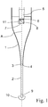
- Figure 1 shows an assembly of a stylus carrier 1 and a hollow stylus 2 dedicated for use in combination with a tactile sensing probe provided with an object-contacting tip 10 , according to the state-of-the-art ( U.S. Patent No. 6 633 051 ).
- the stylus carrier 1 has a trumpet-like shape.
- the stylus 2 is connected with the stylus carrier 1 by connection means 3 at the upper, open end 4 of the stylus, the longitudinal axis of the stylus 2 being aligned with the axis A of the stylus carrier 1.
- an optical monitoring system comprising a laser light source 5 at the output end of which is placed a convex lens 6 for generating a collimated laser beam which is propagated, after passing a beam splitter 7, as a free optical beam within the hollow stylus 2 towards a retro-reflector 9 provided close to the contacting tip 10.
- Light returned by the retro-reflector 9 hits a reflecting surface 8 of the beam splitter 7 under an angle of 45° with respect to the optical axis and the axis A and is reflected at right angles to the axis A towards a position-sensitive detector 11. Any displacements of the contacting tip 10 together with the retro-reflector 9 lead to a lateral displacement of the returned beam in the plane of the detector 11.
- the optical monitoring system including laser light source 5, detector 11 and driver electronics is mounted in the stylus carrier 1, thus enclosing several heat sources in the closed frame formed by the stylus and its carrier and leading to uncontrollable deformations of the measurement system as long as thermal equilibrium is not reached.
- Fig. 2a is illustrated a segmented chromatic filter 100 as an example for an optically encoding component.
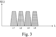
- the filter comprises four segments 101 - 104 corresponding to filters with maximum transmission at four different wavelengths ⁇ 1, ⁇ 2, ⁇ 3 and ⁇ 4, with preferably spectrally non-overlapping transmission ranges, as schematically shown in Fig. 3 (transmission T( ⁇ )).
- the filter transmissions may, for example, be adapted to the radiation channels according to the ITU norm for telecommunication, with a spectral separation of, e.g., 100 GHz or 200 GHz, corresponding to about 0.8 nm or 1.6 nm in the C and L-band.
- the filter may have any geometry, like circular, square-type or polygonal. For purposes of easiness of adjustment in an optical beam path and of system calibration, a point-symmetric shape is preferred.
- the segmented filter is positioned, in an exemplified, ideal case, in the optical path of the returned beam in such a way that in absence of a displacement of said returned beam (because of a displacement of the stylus tip or bending of the stylus), the cross-section 50 of the returned beam in the filter plane is centrally symmetric with respect to the segmented filter / filter segmentation.
- the transmission characteristics of the filter and the spectral composition of the probe beam and consequently also of the returned beam are selected (the latter e.g. by using laser light sources of selected emission wavelengths) in such a way that the transmitted fractions of returned light, after passing the segmented filter, are equal (equal distribution of the transmitted light fractions).
- Fig. 2b shows an alternative embodiment of a segmented chromatic filter as a second example for an optically decoding element.
- the segmented chromatic filter 200 comprises three segments 201, 202 and 203 corresponding to individual filters with maximum transmission at wavelengths ⁇ 1, ⁇ 2 and ⁇ 3, respectively. Concerning convenience of manufacturing, however, a segmented filter with four segments as shown in Fig. 2a is probably preferable.
- Fig. 4a and Fig. 4b illustrate the selection of laser light sources, their emission wavelength being correlated with the selection of a segmented chromatic filter to be used in combination therewith.
- Fig. 4a indicates the emission lines (intensities I( ⁇ )) of four selected individual lasers. The emission wavelengths may vary within the intervals indicated by arrows. A special stabilization of the laser wavelength is not necessary, in contrast to applications in telecommunications, the laser signal being only weakly modulated (in the MHz range) for more stable AC detectability.
- Fig. 4b shows a typical spectral distribution of the light (intensity I( ⁇ )) emitted by a super-luminescent light-emitting diode (SLED), with a bandwidth of typically about 10 nm.
- the SLED has to be chosen in such a way that its emission spans the transmission windows of the segmented chromatic filter (cf. Fig. 3 ), where the returned beam of light from the SLED would be separated into spectrally separated fractions.
- Fig. 5 illustrates a beam distributor 19, comprising beam splitter 17, which is placed in the optical path 55 of the probe beam for in-coupling (IN) and directing the probe beam towards the stylus tip, and out-coupling (OUT) and directing the returned beam towards the at least one detector, upon spatial separation of the probe beam from the returned beam, the latter to be analyzed by an optically encoding component like a segmented chromatic filter 100 as shown in Fig. 2a .
- the returned beam is directed to the optically encoding component, in particular a segmented chromatic filter 100, by passing the beam splitter 17 which may be a 50 % splitter.
- a lateral displacement of the returned beam in the filter plane leads to a change of the distribution of the fractions of transmitted light components, as explained above referring to Fig. 2a .
- the components of the beam distributor 19 may be conglutinated, for example using an optical cement, and form a micro-optical component together with the segmented optical filter 100.
- the filter may be built up on an absorbing black glass with, e.g., 50 % transmission. Upon dual pass through such an absorbing layer, disturbing reflections would then be suppressed by 6 dB, resulting in a 12 dB suppression in combination with the effect of the 50 % beam splitter 17.
- the main reflections are then directed into a light trap 20, for example constituted by an absorbing black glass conglutinated with the beam splitter 17.
- the beam distributor 19 is positioned with a slight tilt with respect to an orthogonal entrance direction 55 of the probe beam and provided with an absorptive aperture.
- Remaining effects of unwanted reflections may be compensated by a calibration of the optical monitoring system.
- Fig. 6a shows schematically a possible configuration for combining the emission from different light sources using a multiplexer 120 and for spectrally separating with a de-multiplexer 130 a combined signal into spectral fractions for their individual detection.
- DFB distributed feedback
- a spectrally combined light signal is guided from the circulator 150 by a second monomode fiber 118 to a de-multiplexer 130, where the light is spectrally separated and then directed to detectors 141 - 144 for individual detection.
- the laser light sources may be modulated.
- the laser diodes 111 - 114 may be modulated at different frequencies. Then, only the signal with the associated modulation frequency is accounted for upon detection.
- Some manufacturers of laser diodes integrate a monitor diode in the housing of a laser diode for the purpose of intensity control. Such an integrated monitor diode can also be used for RIN measurement, provided that the bandwidth of the monitor diode is large enough. Alternatively, a small fraction like 1 % of the emitted power of the laser diode may be supplied to an external monitor diode for RIN control, using an asymmetric optical coupler. In signal processing for controlled noise compensation, possible delay of the monitor diode signal has to be accounted for.
- the multiplexing and de-multiplexing configuration depicted in Fig. 6a can also be integrated into the configuration in combination with the optical sensor.
- the emitted signal guided by optical fiber 117 and the received signal guided by optical fiber 118 can be in-coupled into and out-coupled out of an optical transmission fiber 119 by means of circulator 150.
- Fig. 6b shows a variation of the configuration according to Fig. 6a which simplifies signal detection.
- Each of the four DFB lasers 111 to 114 has a different wavelength and is modulated at a different frequency, so that the different lasers may be identified spectrally and electrically. For signal detection, then only a single detector 145 is needed.
- the Fourier spectrum FT ( Fig. 6c ) of the detected electrical signal then shows four frequencies f1, f2, f3 and f4, the intensities or Fourier coefficients of which are dependent on the intensities of the individual spectral wavelengths.
- the four individual signals can be separated and analyzed.
- the signal strengths as shown in Fig. 6c are equivalent to the spectral intensity distribution.
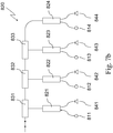
- Fig. 7a and Fig. 7b are illustrated possible embodiments of a multiplexer or a de-multiplexer that can be used in combination with a configuration according to Fig. 6a .
- Multiplexers are standard components in telecommunications and are typically manufactured as planar waveguides or by thin-film technology (TFF).
- TFF thin-film technology
- Fig. 7a shows a possible embodiment of a multiplexer / demultiplexer 720 using beam splitters 717a - 717d for combining a beam to be emitted as a probe beam, supplied from optical fiber collimators 711 - 714.
- the combined beam is directed to optical fiber collimator 719.
- a similar configuration can be used for de-multiplexing a combined beam into its spectral fractions of wavelengths ⁇ 1 - ⁇ 4.
- Fig. 7b illustrates an alternative embodiment of a multiplexer / de-multiplexer 820 comprising add/drop filters 831 - 833 for separating incoming light of combined wavelengths ⁇ 1 - ⁇ 4 into its spectral components for detection by detectors 841 - 844, or for combining light from the laser diodes 811 - 814 to a common probe beam, using optical fiber couplers 821 - 824. Also such a configuration can be manufactured using standard telecommunication components.
- Fig. 7c shows a configuration of a de-multiplexer 830 similar to the one depicted in Fig. 7b , but with a single super-luminescent light emitting diode 825 used as a light source instead of four DFB lasers.
- the polychromatic light coming from circulator 150 is separated into its spectral components ⁇ 1 - ⁇ 4 by the de-multiplexer 830 comprising add/drop filters 831 - 833, for detection by detectors 841 - 844.
- a segmented optical filter 300 as an optically decoding component.
- the filter 300 comprises two different chromatic filter segments 301 and 302, and is provided with a component or functionality to generate a locally in the filter plane varying deflection of the returned beam in a direction perpendicular to its direction of propagation.
- this effect is achieved by a varying thickness 303 of the filter, in this example concerning both segments of different spectral transmission, as shown in a cross-sectional side view of the segmented filter 300.
- the returned beam is deviated and transmitted, when passing through the filter, in a different way depending on its position of impingement on the filter.
- Such a locally varying deflection of the returned beam may also be achieved by separate optical components additional to a segmented filter positioned in the beam path, which additional separate components will then be regarded as parts of the optically encoding component.
- Optically encoding components as shown in Fig. 2a, Fig. 2b and Fig. 8 can also be combined with an additional optical "channel" or segment for transmission of signals from a distance measurement, such as an interferometric distance measurement, for determination of changes in the stylus length.
- a segmented optical filter e.g. with four segments as shown in Fig. 2a , in combination with a beam distributor as depicted in Fig. 5 , for providing four segments for distinction of spectral light components ( ⁇ 1, ⁇ 2, ⁇ 3, ⁇ 4; measurement of the intensities of the transmitted spectral fractions) and one of the four channels also for the determination of a phase change by an interferometric measurement.
- a segmented polarization filter 500 as another possible embodiment of an optically decoding component.
- polarization-maintaining monomode fibers are required for light-guiding. It is preferred that the returned beam impinges in the plane of the segmented polarization filter 500 with 45° polarization.
- Segment 501 of filter 500 is designed for transmission of vertical polarization, segment 502 for horizontal polarization.
- Segment 503 is constituted by a quarter-wave plate.
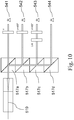
- Fig. 10 is illustrated a possible embodiment of a de-multiplexer having the functionality of a polarimeter setup for determining the polarization state of the returned beam.
- the returned beam is distributed by beam splitters 517a - 517c for detection of the polarization states and the radiation phase by detectors 541 - 543.
- FIG. 11 An assembly comprising a stylus carrier 61, a stylus 62 and an optical monitoring system for a measurement configuration using a segmented chromatic filter as shown in Fig. 2a and a beam distributor as shown in Fig. 5 , for use in combination with a tactile sensor, is illustrated in Fig. 11 .
- the main components of the optical monitoring system not consuming electrical power and producing heat, are housed in the stylus carrier 61 connected with a stylus 62.
- Spectrally distinguishable optical light components from one or more light sources are injected from a circulator 150 into a first optical fiber 117 preferably provided as a monomode fiber, which is connected to a first optical fiber collimator 71.
- the probe beam is directed as a free optical beam towards the stylus tip provided with a retro-reflector 79 and a tactile sensor 80 designed to contact an object (not shown).
- At least parts of the probe beam are reflected by the retro-reflector as a returned beam, the returned beam being subject to a displacement in case of displacement of the stylus tip or bending of the stylus.
- the returned beam then enters the beam distributor 19 comprising at least one beam splitter 17 provided with a light trap 20, e.g. absorbing black glass.
- the light analyzed for the different spectral fractions of the returned beam is collected by optical fiber collimator 72 and launched into the second, preferably monomode fiber 118, from where it is guided to the circulator 150 and further directed to the optical transmission fiber 119, which may be coupled to an opto-mechanical interface.
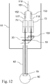
- Fig. 12 shows a configuration similar to the one depicted in Fig. 11 except for replacement of the circulator 150 by a fusion coupler 151 and two insulators 152, 153.
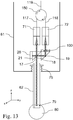
- FIG. 13 An assembly essentially similar to the one depicted in Fig. 11 , comprising a stylus carrier 61, a stylus 62 and an optical monitoring system tailor-made for such a measurement configuration with, in combination, a beam distributor as depicted in Fig. 5 , for providing four segments for distinction of spectral light components ( ⁇ 1, ⁇ 2, ⁇ 3, ⁇ 4; measurement of the intensities of the transmitted spectral fractions), and one of the four channels also for the determination of a phase change by an interferometric measurement, is illustrated in Fig. 13 .
- the main components of the optical monitoring system are housed in the stylus carrier 61 flexibly connected by a spring system 75 with a stylus 62.
- the spring system 75 is designed to allow for vertical displacement of the stylus 62 with its tactile sensor tip, the vertical direction being understood as a Z axis perpendicular to a horizontal plane spanned by an X and a Y axis.
- Spectrally distinguishable optical light components from one or more light sources are injected from a circulator 150 into a first optical fiber 117 preferably provided as a monomode fiber, which is connected to a first optical fiber collimator 71.
- the probe beam is directed as a free optical beam towards the stylus tip provided with a retro-reflector 79 and a tactile sensor 80 designed to contact an object (not shown).
- At least parts of the probe beam are reflected by the retro-reflector as a returned beam, the returned beam being subject to a displacement and a change of the beam path in z-direction upon tactile contact with an object.
- the returned beam then enters the beam distributor 19 comprising at least one beam splitter 17 provided with a light trap 20, e.g. absorbing black glass.
- the reflecting surface 21 of the beam splitter 17 and the light trap 20 are designed in such a way that, in this example, reflections from a segmented filter 100 are directed, concerning light components of three wavelengths, into the light trap where they are absorbed, whereas a light component associated with a fourth wavelength (e.g. ⁇ 1) is reflected by the reflecting surface 21 (e.g. provided with a spectrally selectively reflecting coating) and is brought into interference with the light component of this wavelength ⁇ 1 transmitted by the segmented filter 100.
- a fourth wavelength e.g. ⁇ 1
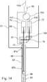
- Fig. 14 illustrates a configuration using an optical sensor instead of a tactile sensor for the distance measurement.
- the setup is similar to the one of Fig. 11 or Fig. 13 , also concerning the design of the beam distributor 19 and the segmented chromatic filter 100.
- an optical probe 85 is used instead of a tactile sensor tip for providing a signal representing an optical distance measurement.
- This signal is transmitted from the optical probe 85 comprising an optical fiber collimator 86 by an optical fiber 88 to a wavelength division multiplexer (WDM)89, e.g. designed for wavelengths around 1300 nm and around 1500 nm.
- WDM wavelength division multiplexer
- the de-multiplexed signal is directed from the WDM into the optical transmission fiber 119, to be further guided, for example, to an opto-mechanical interface.
- optical fiber 88 blocks or shadows the optical path of probe beam and returned beam of the monitoring system. Therefore, optical fiber 88, being directed at the inside of the stylus 62 from the wavelength demultiplexer (WDM) 89 to the optical probe 85 is attached by fixations 87a, 87b at an inside wall of the stylus 62.
- WDM wavelength demultiplexer
- a stylus 62' provided as a double tubus 84 with a double inner wall for receiving optical fiber 88 may be used ( Fig. 15 ).
- Fig. 16 illustrates a surface sensing device with an optical sensor, the sensing device being provided with a rotary actuator (C axis), which is particular versatile for measuring internal bores, e.g. cylinders.
- the base design is similar to the setup shown in Fig. 14 . In contrast, however, an optical probe 85' with rectangular beam deflection is provided.
- the stylus 62 is connected to the stylus carrier 61 conveyed by the rotary actuator comprising a motor 90, decoders 91 for the motor rotation and a bearing 92.
- the latter In order to allow rotation of the distance measuring optical fiber 88', the latter one is provided with a fiber coil 88'a.
- a potential issue of this configuration is the axial impact, depending on angular position, rotational speed and orientation of the measuring head (horizontal or vertical, etc.).
- a direct contacting of the probe tip is possible.
- Fig. 17a shows a variation of the configuration according to Fig. 16 .
- This embodiment based on use of an optical rotary coupler 93 for the optical fiber 88, is designed for allowing unlimited rotation of the stylus 62.
- the lower part of the rotary coupler 93 is connected and is rotatable together with stylus 62, whereas the upper part of rotary coupler 93 is stationary.
- a stationary prism-like beam deviator 95 is connected to the stylus 62.
- optical fiber 88 connected with the rotatable upper part of rotary coupler 93 must be directed free to move across the location of beam deviator 95.
- Such fiber lead-through 94 may be placed slightly aside of beam deviator 95 and the optical beam path of probe und returned beam.
- optical fiber 88 will cross the beam path.
- a thin optical fiber preferably with a diameter below 125 ⁇ m at least in the region of beam crossing, should be chosen in order to minimize shadowing of the beam. A satisfying precision for a determination of the beam position also in this region is possible upon a rotating calibration measurement.
- the probe head - that is the stylus carrier 161 with the attached stylus 162 - may be connected to a socket of the end of an arm of an articulated arm measuring machine or to of the Z-column of a bridge-type coordinate measuring machine, the socket acting as a holding means, conveyed by rotation axes 926, 927 providing rotary degree of freedom of the stylus carrier 161 with respect to the holding means.
- Fig. 17b an example is illustrated with two rotation axes providing freedom of rotation of the stylus carrier around two perpendicular axes. Such a configuration is particularly advantageous for scanning applications in order to follow precisely the surface of an object.
- Fig. 18 shows a segmented chromatic filter with two segments dedicated for a combination, e.g., with a segmented chromatic filter as shown in Fig. 2a for a surface sensing device provided with 3-axes measurement capability.
- the position of the stylus with respect to the Z direction is determined using a 90°-deviating beam splitter, perpendicular to the z-direction of motion (see Fig. 22 ).
- the returned beam is directed onto a 2-segments filter 600 as part of an optically decoding component, the filter comprising two segments 105 and 106 of different, preferably non-overlapping spectral transmission.
- the filter is preferably placed in the beam path of the returned beam in such a way that, without displacement upon interaction with an object, the returned beam has a mirror-symmetrical cross section 50 on the two filter segments.
- the returned beam Upon displacement of the stylus in Z direction, the returned beam impinges on the 2-segmented filter with a lateral displaced beam cross section 50".
- the segments 105 and 106 of 2-segment filter 600 are selected in such a way that their spectral transmission windows accomplish the spectral range covered by the transmissions of a segmented chromatic filter as illustrated in Fig. 2a (see Fig. 19 : spectral ranges around ⁇ 1 to ⁇ 4 covered by segments of segmented chromatic filter 100(X,Y), adjacent to spectral range ( ⁇ 5, ⁇ 6) covered by the two segments of 2-segments filter 600(Z)).
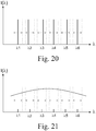
- each laser light source may be used, with their emission wavelengths falling into the spectral ranges of the segmented chromatic filters as shown in Fig. 20 .
- the emission wavelengths may vary within the intervals indicated by arrows.
- a super-luminescent light-emitting diode with a spectral emission band spanning the transmission windows of all six filter segments may be used ( FIG. 21).
- Fig. 21 shows a typical spectral distribution of the light emitted by a super-luminescent light-emitting diode (SLED), with a bandwidth of typically about 10 nm.
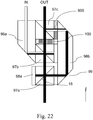
- Fig. 22 shows a possible configuration of a beam distributor 99 with beam splitters for use with a combination of segmented chromatic filters 100 and 600.
- the beam distributor 99 comprises beam-deviating prisms 96a, 96b, beam splitters 97a, 97b, 97c, and segmented chromatic filters 100, 600, the lower beam splitter 97a with an absorbing back side 98a, e.g. of black glass being attached to the upper stylus end movable in Z direction, whereas the other parts of beam distributor 99 are housed fixed in the stylus carrier 61.
- the returned beam is split by e.g. 50% beam splitter 97a into two parts, one part propagating towards beam splitter 97b, also provided with an absorbing back side 98b and carrying segmented chromatic filter 100, the other part being directed over prism 96b to segmented chromatic filter 600.
- Both beams after spectral separation into light components, are combined by a chromatic beam splitter 97c to a common beam to be further guided together in one optical fiber ("OUT").
- Fig. 23 illustrates a de-multiplexing configuration for use in combination with super-luminescent light-emitting diode 825', as shown in Fig. 7c , but now accomplished by two further spectral separation channels, using additional add/drop filters 834 and 835 for separating light components of wavelengths ⁇ 5 and ⁇ 6 to be detected by detectors 845 and 846.
- FIG. 24 An assembly comprising a stylus carrier 61, a stylus 62 and an optical monitoring system designed for optical measurement with respect to X, Y and Z direction is illustrated in Fig. 24 .
- the configuration comprises a spring system 75 for allowing vertical displacement of the stylus 62 with its sensor tip 80, the vertical direction being understood as a Z axis perpendicular to a horizontal plane spanned by an X and a Y axis.
- the configuration is largely similar to the one shown in Fig. 13 , with the difference of beam distributor 69 being replaced by beam distributor 99, which has been described in detail with reference to Fig. 22 .
- the main components of the optical monitoring system are housed in the stylus carrier 61 flexibly connected by a spring system 75 with a stylus 62.
- Spectrally distinguishable optical light components from one or more light sources are injected from a circulator 150 into a first optical fiber 117 preferably provided as a monomode fiber, which is connected to a first optical fiber collimator 71.
- the probe beam is directed as a free optical beam towards the stylus tip provided with a retro-reflector 79 and a tactile sensor 80 designed to contact an object (not shown).
- At least parts of the probe beam are reflected by the retro-reflector as a returned beam, the returned beam being subject to a displacement and a change of the beam path in z-direction upon tactile contact with an object.
- the returned beam then enters the beam distributor 99, the functionality of which having been described with reference to Fig. 22 .
- the different embodiments of surface sensing devices may also comprise, instead of a tactile sensor 80 as shown in Fig. 11 to Fig. 13 or an optical sensor 85 or 85' as shown in Fig. 14 to Fig. 17 or in Fig. 24 , a combined optical-tactile sensor.
- a tactile sensor 80 as shown in Fig. 11 to Fig. 13
- an optical sensor 85 or 85' as shown in Fig. 14 to Fig. 17 or in Fig. 24
- Such an optical-tactile sensor may be provided like a spherical sensor tip of a typical tactile sensor, but the sphere being light-transmissive or having a perforation for light transmission.
- Fig. 25 illustrates an articulated arm coordinate measuring machine (CMM) 900 equipped with a stylus 162 attached to a stylus carrier 161.
- the articulated arm CMM 900 comprises a base 920 which forms the support of the CMM and houses light sources 911 and detectors 941, as schematically indicated. Connected to the base 900 several arm-components are linked by joints, the arm-components being thus movable relative against each other.
- the optical components provided in the stylus carrier 161 and/or the stylus 162, as described above, are connected with the light sources 911 and the detectors 941 housed in the base 920 by optical fibers 917 and 918, as schematically shown.
- a bridge-type CMM is shown in Fig. 26 .
- the bridge-type CMM comprises two portal legs 921, 922 supporting a bridge 923 and an X-carriage 924 which can be driven along the bridge (X-direction).
- a Z-column 925 movable in Z-direction, holds a stylus carrier 161 with an attached stylus 162.
- the portal formed by the portal legs 921, 922 and the bridge 923 can be moved in Y-direction.
- Light sources and detectors housed e.g. in a CMM controller are again connected by optical fibers with the components of the optical monitoring system provided in the stylus carrier 161 or the stylus 162, as shown above.
- the probe beam has a diameter of 1.2 mm.
- the Rayleigh length of about 70 cm is larger than twice the measurement distance using a stylus of 30 cm length. Consequently, the beam can be presumed to be collimated over the whole length of free beam propagation.
- the measured intensity distribution of the light components of the returned beam, after passing a segmented chromatic filter as described with reference to Fig. 2a is displayed in Fig. 27a - 27d .
- the total area covered by the segmented filter (image size) is (4 mm) 2 .
- the returned beam is displaced by 100 ⁇ m towards the bottom ( Fig. 27c, Fig. 27d ).
- the launched optical power in the probe beam had been 1 mW in each of the four spectral light components.
- the transmission of the two lower channels is higher the one of the upper channels, due to the beam displacement.
- the four beam parts propagate independent on one another towards the lens of the optical fiber collimator (Grin lens) and further to the optical fiber:
- Fig. 28 shows in its upper part the mode of the optical fiber, in a cross-sectional view.
- the two lower parts of Fig. 28 show intensity profiles in X and Y direction for one of the four free propagating partial beams.
- the segmented chromatic filter being located in the Fourier plane (entrance pupil plane of the optical fiber collimator), shadowing of the pupil does not lead to a beam displacement, but effects only the beam diameter and the phase.
- the beams are made symmetrical in the optical fiber plane.
- C r : ⁇ i ⁇ j E r i , j ⁇ E Fiber i , j ⁇ 2 ⁇ i ⁇ j E r i , j ⁇ E r i , j ⁇ ⁇ ⁇ i ⁇ j E Fiber i , j ⁇ E Fiber i , j ⁇ fiber coupling efficiency
- C 27.173 27.173 26.82 26.82 ⁇ %
- the position of the returned beam is decoded in the intensity spectrum of the four optical channels as can be seen in Fig. 30 for the example of a beam displacement by 100 ⁇ m.
- the returned beam is displaced in an oblique direction.
- the position for x and y can be determined from the intensities ( Fig. 31 ).
- the calibration is only linear in a first approximation, and for achieving a higher precision, two or three parameters should be used for calibration.
Landscapes
- Physics & Mathematics (AREA)
- General Physics & Mathematics (AREA)
- Length Measuring Devices By Optical Means (AREA)
- Length Measuring Devices With Unspecified Measuring Means (AREA)
- A Measuring Device Byusing Mechanical Method (AREA)
- Testing Or Calibration Of Command Recording Devices (AREA)
Claims (15)
- Dispositif de détection de surface comprenant :• une base,• une tête de sonde pour établir et maintenir une connexion de mesure par contact ou sans contact avec une surface à mesurer, la tête de sonde étant liée de manière mobile à la base par au moins une articulation, cependant que la tête de sonde comprend un porteur de stylet (61, 161) et un stylet creux (62, 62', 162) avec une pointe de stylet et• un système de surveillance optique pour mesurer un déplacement de la pointe du stylet par rapport au porteur de stylet, le système de surveillance optique comprenant :• des moyens d'émission de lumière (111, 112, 113, 114, 811, 812, 813, 814, 825, 825', 911) pour générer un faisceau à diriger à l'intérieur du stylet (62, 62', 162) vers la pointe de stylet où au moins des parties du faisceau sont réfléchies comme un faisceau réfléchi qui se propage le long d'un trajet optique de retour et• des moyens détecteurs (141, 142, 143, 144, 145, 541, 542, 543, 544, 841, 842, 843, 844, 845, 846, 941) pour le faisceau réfléchi qui sont capables de générer un signal électrique de sortie qui indique le déplacement de la pointe du stylet, cependant que• les moyens d'émission de lumière sont construits de telle manière que le faisceau a au moins deux caractéristiques de lumière distinctes avec une répartition des caractéristiques donnée, caractérisée en ce que• le système de surveillance optique comprend de plus un composant de codage optique (100, 200, 300, 500, 600) positionné dans le porteur de stylet (61, 161) dans le trajet optique de retour et conçu pour transformer les informations sur une position d'impact (50, 50') du faisceau réfléchi sur le composant de codage optique (100, 200, 300, 500, 600) en un changement de la répartition des caractéristiques du faisceau réfléchi et• les moyens détecteurs (141, 142, 143, 144, 145, 541, 542, 543, 544, 841, 842, 843, 844, 845, 846, 941) sont sensibles aux au moins deux caractéristiques de lumière distinctes et construits pour générer le signal électrique de sortie en fonction de la répartition modifiée des caractéristiques du faisceau réfléchi.
- Dispositif de détection de surface selon la revendication 1, caractérisé en ce que le composant de codage optique (100, 200, 300, 500, 600) est conçu de telle manière que la répartition des caractéristiques du faisceau réfléchi est modifiée en fonction de la position d'impact du faisceau réfléchi sur le composant de codage optique (100, 200, 300, 500, 600) si bien que le faisceau réfléchi avec la répartition modifiée des caractéristiques qui se propage à partir du composant de codage optique (100, 200, 300, 500, 600) vers les moyens détecteurs (141, 142, 143, 144, 145, 541, 542, 543, 544, 841, 842, 843, 844, 845, 846, 941) est révélateur du déplacement de la pointe du stylet indépendamment d'un parcours exact de propagation du faisceau réfléchi à l'intérieur du trajet optique de retour de manière à activer le guidage d'ondes optique du faisceau réfléchi avec la répartition modifiée des caractéristiques vers les moyens détecteurs par une fibre optique sans perdre l'indication optique du déplacement de la pointe du stylet portée par le faisceau réfléchi.
- Dispositif de détection de surface selon la revendication 1 ou 2, caractérisé en ce que• le dispositif de détection de surface est prévu comme machine de mesure de coordonnées avec un bras articulé dont l'une des extrémités forme la base et l'autre extrémité comprend un connecteur pour fixer la tête de la sonde de manière amovible,• les moyens d'émission de lumière (111, 112, 113, 114, 811, 812, 813, 814, 825, 825', 911), qui comprennent en particulier une ou plusieurs sources de lumière laser, et les moyens détecteurs (141, 142, 143, 144, 145, 541, 542, 543, 544, 841, 842, 843, 844, 845, 846, 941), qui comprennent en particulier un ou plusieurs détecteurs de lumière, sont positionnés à l'extérieur de la tête de la sonde, en particulier cependant que les moyens d'émission de lumière (111, 112, 113, 114, 811, 812, 813, 814, 825, 825', 911) et les moyens détecteurs (141, 142, 143, 144, 145, 541, 542, 543, 544, 841, 842, 843, 844, 845, 846, 941) sont logés dans la base et• le faisceau généré par les moyens d'émission de lumière (111, 112, 113, 114, 811, 812, 813, 814, 825, 825', 911) aussi bien que le faisceau réfléchi qui se propage à partir du composant de codage optique (100, 200, 300, 500, 600) vers les moyens détecteurs (141, 142, 143, 144, 145, 541, 542, 543, 544, 841, 842, 843, 844, 845, 846, 941) dont les ondes sont guidées dans le bras articulé par les fibres optiques, en particulier cependant que le faisceau est découplé d'une fibre de transmission (119) et le faisceau réfléchi y est couplé en utilisant un circulateur (150) comme dispositif de guidage de faisceau ou• le dispositif de détection de surface est prévu comme machine de mesure de coordonnées de type pont qui comprend :▪ deux montants de portique (921, 922), les montants de portique (921, 922) étant reliés de manière mobile à la base et supportant un pont (923),▪ un chariot mobile en X (924) le long du pont et▪ une colonne (925) qui est reliée de manière mobile en Z au chariot (924) et qui comprend un connecteur pour fixer la tête de la sonde de manière amovible,en particulier cependant que le connecteur procure un degré de liberté de rotation de la tête de la sonde respectivement par rapport à la colonne mobile en Z (925) ou à l'autre extrémité du bras articulé.
- Dispositif de détection de surface selon l'une quelconque des revendications 1 à 3, caractérisé en ce que les au moins deux caractéristiques de lumière distinctes sont données par des composants de lumière du faisceau généré qui ont• différentes longueurs d'ondes ou plages de longueurs d'ondes et/ou• différents états de polarisation etla répartition des caractéristiques est donnée par une proportion ou une fraction de chaque composant de lumière.
- Dispositif de détection de surface selon l'une quelconque des revendications 1 à 4, caractérisé en ce que le composant de codage optique (100, 200, 300, 500, 600) comprend un filtre optique segmenté (100, 200, 300, 500, 600) situé dans un plan de pupille d'entrée d'un second collimateur pour fibres optiques (72) dans le trajet optique de retour, le filtre (100, 200, 300, 500, 600) comprenant au moins deux segments (101, 102, 103, 104, 105, 106, 201, 202, 203, 301, 302, 501, 502, 503) de différentes caractéristiques de transmission, de préférence qui ne se chevauchent pas, en particulier cependant que le filtre optique segmenté (100, 200, 300, 500, 600) est un filtre chromatique (100, 200, 300, 600) pourvu de fenêtres de transmission dont les spectres ne se chevauchent pas avec une distance spectrale de 100 ou 200 GHz, c'est-à-dire de 0,8 nm ou 1,6 nm dans la bande C et la bande L selon la norme UIT de télécommunication.
- Dispositif de détection de surface selon l'une quelconque des revendications 1 à 5, caractérisé en ce que le composant de codage optique (100, 200, 300, 500, 600) comprend un composant de réfraction optique (303) pour le faisceau réfléchi capable d'une déflexion variante localement du faisceau réfléchi dans le plan de réception dans une direction perpendiculaire à la direction de propagation du faisceau réfléchi.
- Dispositif de détection de surface selon l'une quelconque des revendications 1 à 6, le stylet creux (62, 62', 162) ayant une longueur de stylet, caractérisé en ce que le composant de codage optique (100, 200, 300, 500, 600)▪ comprend un segment conçu pour la transmission de signal pour une mesure interférométrique de la distance pour déterminer des changements dans la longueur du stylet et/ou▪ est un filtre optique segmenté (500) et est pourvu de segments (501, 502) avec une transmission à polarisation sélective, en particulier comprenant de manière additionnelle une lame quart d'onde (503) permettant la détermination d'une relation de phase entre les trajets du faisceau réfléchi de différente polarisation en utilisant un polarimètre.
- Dispositif de détection de surface selon l'une quelconque des revendications 1 à 7, caractérisé en ce que le faisceau réfléchi est dirigé sur le composant de codage optique (100, 200, 300, 500, 600) après être passé par au moins un séparateur de faisceau (17, 97a, 97b) qui forme un répartiteur de faisceau (19, 99), en particulier cependant que le répartiteur de faisceau (19, 69) est prévu avec le composant de codage optique (100, 200, 300) comme composant micro-optique qui est collé ensemble, ledit composant micro-optique étant en particulier pourvu d'un piège à lumière (20), en particulier d'un dos en verre noir absorbant pour réduire les réflexions de la lumière non transmise.
- Dispositif de détection de surface selon l'une quelconque des revendications 1 à 8, caractérisé en ce que• les moyens d'émission de lumière (111, 112, 113, 114, 811, 812, 813, 814, 825, 825', 911) sont une multitude de sources de lumière laser (111, 112, 113, 114, 811, 812, 813, 814, 911) qui émettent à différentes longueurs d'ondes▪ en particulier cependant que le système de surveillance optique est en plus pourvu d'un multiplexeur (120, 720, 820) conçu pour combiner le spectre de la lumière des différentes longueurs d'ondes de la multitude des sources de lumière laser (111, 112, 113, 114, 811, 812, 813, 814, 911) et pour coupler la lumière combinée dans une première fibre optique (117) qui quitte le multiplexeur
et les moyens détecteurs (141, 142, 143, 144, 145, 541, 542, 543, 544, 841, 842, 843, 844, 845, 846, 941) sont formés par une multitude de détecteurs (141, 142, 143, 144, 145, 541, 542, 543, 544, 841, 842, 843, 844, 845, 846, 941) sensibles aux différentes longueurs d'ondes,▪ en particulier cependant que le système de surveillance optique est de plus pourvu d'un démultiplexeur (130, 720, 820, 830, 830') conçu pour séparer le spectre de la lumière du faisceau réfléchi en fractions de faisceau des différentes longueurs d'ondes pour la détection par la multitude de détecteurs (141, 142, 143, 144, 145, 541, 542, 543, 544, 841, 842, 843, 844, 845, 846, 941) ou les moyens d'émission de lumière sont une diode émettrice de lumière supra-luminescente (825, 825'), en particulier avec une bande d'émission d'environ 10 nm de largeur de bande, dont l'émission spectrale est séparée dans le faisceau réfléchi par le composant de codage optique (100, 200, 300, 600) en une pluralité de faisceaux partiels de différentes longueurs d'ondes qui doit être fournie aux moyens détecteurs (141, 142, 143, 144, 145, 541, 542, 543, 544, 841, 842, 843, 844, 845, 846, 941) ou▪ les moyens d'émission de lumière (111, 112, 113, 114, 811, 812, 813, 814, 825, 825', 911) sont une multitude de sources de lumière laser (111, 112, 113, 114, 811, 812, 813, 814, 911) qui émettent à différentes longueurs d'ondes et qui sont modulées à différentes fréquences qui correspondent aux fréquences multiples (f1, f2, f3, f4) dans un spectre de Fourier et les moyens détecteurs (145) sont sensibles aux caractéristiques de lumière distinctes, les signaux individuels étant séparables par démodulation analogique ou numérique. - Dispositif de détection de surface selon l'une quelconque des revendications 1 à 9, caractérisé en ce que• la tête de la sonde comprend un capteur tactile (80) pour établir et maintenir une connexion de mesure par contact avec la surface à mesurer, le capteur tactile (80) étant de préférence pourvu d'un rétroréflecteur (79), ou• la tête de la sonde comprend un capteur optique et tactile pour établir et maintenir une connexion de mesure par contact avec la surface à mesurer, le capteur optique et tactile comprenant une pointe de capteur qui transmet la lumière ou une pointe de capteur perforée pour la transmission de la lumière ou• la tête de la sonde comprend un capteur optique (85, 85') pour établir et maintenir une connexion de mesure sans contact avec la surface à mesurer, le capteur optique (85, 85') étant de préférence pourvu d'une fibre monomode (88) qui s'étend d'un multiplexeur de division de longueur d'ondes (89) jusqu'à la pointe du stylet, en particulier cependant▪ qu'un actionneur rotatif est prévu, le stylet (62, 62', 162) étant relié au porteur de stylet (61, 161) transporté par l'actionneur rotatif et comprenant une fibre qui mesure la distance (88'), de préférence avec une bobine de fibre (88'a) ou▪ il est pourvu d'un coupleur rotatif optique (93) pour la fibre monomode (88) conçu pour permettre une rotation illimitée du stylet (62, 62', 162), une partie du coupleur rotatif optique (93) étant reliée et rotative avec le stylet (62, 62', 162) tandis qu'une autre partie du coupleur rotatif (93) est stationnaire.
- Dispositif de détection de surface selon l'une quelconque des revendications 1 à 10, caractérisé en ce qu'il est pourvu d'une aptitude à mesurer selon 3 axes (X, Y, Z) comprenant :• un filtre chromatique segmenté supplémentaire (600) pourvu d'au moins deux segments (105, 106) de caractéristiques de transmission de préférence dont les spectres ne se chevauchent pas et• un répartiteur de faisceau (99) avec des séparateurs de faisceaux à utiliser avec une combinaison de filtres optiques segmentés (100, 200, 300, 600), le répartiteur de faisceau (99) comprenant des prismes de déviation de faisceau (96a, 96b), des séparateurs de faisceaux (971, 97b, 97c) et des filtres chromatiques segmentés (100, 200, 300, 600), un séparateur de faisceau inférieur (97a) étant fixé à un stylet supérieur et mobile dans la direction Z, tandis que les autres parties du répartiteur de faisceau (99) sont logées de manière fixe dans le porteur de stylet (61), cependant que le faisceau réfléchi est divisé par le séparateur de faisceau inférieur (97a) en deux parties, une partie qui se propage vers un séparateur de faisceau (97b) qui porte un filtre chromatique segmenté (100, 200, 300), l'autre partie étant dirigée vers le filtre chromatique segmenté supplémentaire (600) en passant par un prisme (96b).
- Tête de sonde pour un dispositif de détection de surface selon l'une quelconque des revendications 1 à 11, la tête de sonde étant formée pour établir et maintenir une connexion de mesure par contact ou sans contact avec la surface à mesurer, cependant que la tête de sonde comprend un porteur de stylet (61, 161) et un stylet creux (62, 62', 162) avec une pointe de stylet, cependant que• la tête de sonde comprend des moyens pour recevoir un faisceau - qui a au moins deux caractéristiques de lumière distinctes avec une répartition des caractéristiques donnée - du dispositif de détection de surface dont les ondes sont guidées par une fibre optique et des moyens pour découpler le faisceau de la fibre optique et le diriger à l'intérieur du stylet (62, 62', 162) vers la pointe de stylet où au moins des parties du faisceau sont réfléchies en tant que faisceau réfléchi qui se propage le long d'un trajet optique de retour, caractérisée en ce que la tête de sonde comprend de plus :• un composant de codage optique (100, 200, 300, 500, 600) en tant que partie d'un système de surveillance optique pour mesurer un déplacement de la pointe du stylet par rapport au porteur de stylet, le composant de codage optique (100, 200, 300, 500, 600) étant positionné dans le porteur de stylet (61, 161) dans le trajet optique de retour et conçu pour transformer les informations sur une position d'impact du faisceau réfléchi sur le composant de codage optique (100, 200, 300, 500, 600) en un changement de la répartition des caractéristiques du faisceau réfléchi et• des moyens pour coupler le faisceau réfléchi - qui a la répartition de caractéristiques modifiée - dans une fibre optique de manière à permettre le guidage d'ondes optique du faisceau réfléchi dans le dispositif de détection de surface.
- Tête de sonde selon la revendication 12, caractérisé en ce que le porteur de stylet (61, 161) comprend au moins l'un des éléments suivants :• un circulateur (150) relié à une fibre de transmission (119) et à une première fibre optique (117) et à une seconde fibre optique (118) pour▪ injection du faisceau reçu par la fibre de transmission (119) dans la première fibre optique (117) reliée à un collimateur de première fibre optique (71) et▪ injection du faisceau réfléchi - qui a été couplé dans la seconde fibre optique (118) par un collimateur de seconde fibre optique (72) - dans la fibre de transmission optique (119),• un répartiteur de faisceau (19, 99) qui comprend un séparateur de faisceau (18, 971, 97b).
- Procédé de surveillance pour une tête de sonde d'un dispositif de détection de surface, la tête de sonde comprenant un porteur de stylet (61, 161) et un stylet creux (62, 62', 162) avec une pointe de stylet, le procédé de surveillance étant conçu pour mesurer un déplacement de la pointe du stylet par rapport au porteur de stylet, le procédé de surveillance comprenant :• la direction d'un faisceau - qui a au moins deux caractéristiques de lumière distinctes avec une répartition des caractéristiques donnée - à l'intérieur du stylet (62, 62', 162) vers la pointe de stylet où au moins des parties du faisceau sont réfléchies comme un faisceau réfléchi qui se propage le long d'un trajet optique de retour,• la transformation▪ des informations d'une position d'impact (50, 50') du faisceau réfléchi sur le composant de codage optique (100, 200, 300, 500, 600) positionné dans le porteur de stylet (61, 161) dans le trajet optique de retour▪ en un changement de la répartition des caractéristiques du faisceau réfléchi,• la détection des au moins deux caractéristiques de lumière distinctes du faisceau réfléchi et• la détermination du déplacement de la pointe du stylet par rapport au porteur de stylet en fonction de la répartition modifiée des caractéristiques du faisceau réfléchi,• en particulier cependant que - après l'étape de transformation - une fibre optique guide les ondes du faisceau réfléchi.
- Procédé de surveillance selon la revendication 14, caractérisé en ce que le déplacement de la pointe du stylet est déterminé dans une direction X et/ou Y par rapport au porteur de stylet (61, 161), en particulier cependant que le déplacement de la pointe du stylet est déterminé de plus dans une direction Z par• la déflexion du faisceau réfléchi en fonction du déplacement dans la direction Z avant d'exécuter l'étape de transformation et ensuite détermination du déplacement de la pointe du stylet aussi dans la direction Z en fonction de la répartition modifiée des caractéristiques du faisceau réfléchi ou• l'utilisation d'un système de mesure électronique de distance, en particulier avec un capteur inductif.
Priority Applications (1)
| Application Number | Priority Date | Filing Date | Title |
|---|---|---|---|
| EP11716911.0A EP2567185B1 (fr) | 2010-05-05 | 2011-04-27 | Dispositif de détection de surface comportant un système de contrôle optique, tête de mesure et procédé de contrôle |
Applications Claiming Priority (3)
| Application Number | Priority Date | Filing Date | Title |
|---|---|---|---|
| EP10162017A EP2385339A1 (fr) | 2010-05-05 | 2010-05-05 | Dispositif de détection de surface doté d'un système de surveillance optique |
| PCT/EP2011/056689 WO2011138206A1 (fr) | 2010-05-05 | 2011-04-27 | Dispositif de détection de surface comportant un système de contrôle optique |
| EP11716911.0A EP2567185B1 (fr) | 2010-05-05 | 2011-04-27 | Dispositif de détection de surface comportant un système de contrôle optique, tête de mesure et procédé de contrôle |
Publications (2)
| Publication Number | Publication Date |
|---|---|
| EP2567185A1 EP2567185A1 (fr) | 2013-03-13 |
| EP2567185B1 true EP2567185B1 (fr) | 2021-06-09 |
Family
ID=42316037
Family Applications (2)
| Application Number | Title | Priority Date | Filing Date |
|---|---|---|---|
| EP10162017A Withdrawn EP2385339A1 (fr) | 2010-05-05 | 2010-05-05 | Dispositif de détection de surface doté d'un système de surveillance optique |
| EP11716911.0A Active EP2567185B1 (fr) | 2010-05-05 | 2011-04-27 | Dispositif de détection de surface comportant un système de contrôle optique, tête de mesure et procédé de contrôle |
Family Applications Before (1)
| Application Number | Title | Priority Date | Filing Date |
|---|---|---|---|
| EP10162017A Withdrawn EP2385339A1 (fr) | 2010-05-05 | 2010-05-05 | Dispositif de détection de surface doté d'un système de surveillance optique |
Country Status (9)
| Country | Link |
|---|---|
| US (1) | US9316473B2 (fr) |
| EP (2) | EP2385339A1 (fr) |
| JP (1) | JP5629818B2 (fr) |
| KR (1) | KR101495670B1 (fr) |
| CN (1) | CN102869949B (fr) |
| AU (1) | AU2011250101B2 (fr) |
| BR (1) | BR112012028084B1 (fr) |
| CA (1) | CA2798370C (fr) |
| WO (1) | WO2011138206A1 (fr) |
Families Citing this family (29)
| Publication number | Priority date | Publication date | Assignee | Title |
|---|---|---|---|---|
| EP2194357A1 (fr) * | 2008-12-03 | 2010-06-09 | Leica Geosystems AG | Elément de capteur optique pour une machine de mesure et élément de couplage du côté de la machine de mesure correspondant |
| JP4748287B2 (ja) * | 2009-03-24 | 2011-08-17 | コニカミノルタオプト株式会社 | 形状測定装置 |
| DE102012003223A1 (de) * | 2012-02-20 | 2013-08-22 | Carl Zeiss 3D Automation Gmbh | Kugel-Schaft-Verbindung |
| US8786866B2 (en) * | 2012-03-02 | 2014-07-22 | Baker Hughes Incorporated | Apparatus and method for determining inner profiles of hollow devices |
| US8910391B2 (en) * | 2013-01-24 | 2014-12-16 | Faro Technologies, Inc. | Non-articulated portable CMM |
| US10156488B2 (en) * | 2013-08-29 | 2018-12-18 | Corning Incorporated | Prism-coupling systems and methods for characterizing curved parts |
| DE102013015237A1 (de) * | 2013-09-13 | 2015-03-19 | Blum-Novotest Gmbh | Rauheits-Messinstrument zum Einsatz in einer Werkzeugmaschine und Verfahren zur Rauheitsmessung in einer Werkzeugmaschine |
| JP6065875B2 (ja) * | 2014-06-02 | 2017-01-25 | 横河電機株式会社 | 偏光検査装置 |
| US9919958B2 (en) | 2014-07-17 | 2018-03-20 | Corning Incorporated | Glass sheet and system and method for making glass sheet |
| JP6717805B2 (ja) * | 2014-09-08 | 2020-07-08 | コーニンクレッカ フィリップス エヌ ヴェKoninklijke Philips N.V. | 光学形状検知による表面接触の検出 |
| US9791262B2 (en) * | 2015-12-17 | 2017-10-17 | Mitutoyo Corporation | Measurement device with multiplexed position signals |
| US9803972B2 (en) | 2015-12-17 | 2017-10-31 | Mitutoyo Corporation | Optical configuration for measurement device |
| US10281320B2 (en) * | 2015-12-29 | 2019-05-07 | Bio-Rad Laboratories, Inc. | Optical detection system with light sampling |
| FR3048077B1 (fr) * | 2016-02-23 | 2020-05-22 | Mesure-Systems3D | Dispositif de controle tridimensionnel sans contact d'une piece creuse a surface interne de revolution, procede, produit programme d'ordinateur et medium de stockage correspondants |
| ITUB20161099A1 (it) * | 2016-02-26 | 2017-08-26 | Marposs Spa | Dispositivo inseguitore per la misura del profilo di un pezzo meccanico |
| CN105783772B (zh) * | 2016-03-07 | 2018-06-26 | 合肥工业大学 | 单传感器式三维微纳米接触触发测量探头 |
| CN109313018B (zh) * | 2016-06-08 | 2021-12-10 | 索尼公司 | 成像控制装置和方法、以及车辆 |
| US10101141B2 (en) | 2016-12-07 | 2018-10-16 | Mitutoyo Corporation | Trigger counter for measurement device with count values stored in flash memory |
| US10006757B1 (en) * | 2017-06-16 | 2018-06-26 | Mitutoyo Corporation | Optical configuration for measurement device using emitter material configuration with quadrant photodetectors |
| US10473451B2 (en) * | 2017-08-07 | 2019-11-12 | Apre Instruments, Inc. | Measuring the position of objects in space |
| CN109637064B (zh) * | 2019-01-29 | 2021-06-11 | 深圳市汉明电子有限公司 | 物体变形预警监测系统和方法 |
| KR102143388B1 (ko) * | 2019-05-29 | 2020-08-11 | 한국산업기술시험원 | 레일 하부에 지지대가 구성된 측정 장치 및 방법 |
| KR102175321B1 (ko) * | 2020-05-25 | 2020-11-06 | 주식회사 대연 | 측정기용 탐침 |
| EP3954966A1 (fr) * | 2020-08-14 | 2022-02-16 | Hexagon Technology Center GmbH | Compensation de table rotative |
| JP7695354B2 (ja) * | 2020-11-05 | 2025-06-18 | ヴァイナート インダストリーズ アー・ゲー | センシング装置 |
| JP7530272B2 (ja) * | 2020-11-06 | 2024-08-07 | 株式会社ミツトヨ | 形状測定装置および異常検出方法 |
| KR102446916B1 (ko) * | 2022-06-03 | 2022-09-23 | 주식회사 보나 | 광융착 광파이버를 이용한 광 산란 기반의 광학식 전자펜 |
| KR102486202B1 (ko) * | 2022-09-15 | 2023-01-10 | 주식회사 보나 | 광 산란제 펜팁을 구비한 광학식 전자펜 |
| JP2024140995A (ja) * | 2023-03-28 | 2024-10-10 | 株式会社東京精密 | プローブ及び形状測定装置 |
Family Cites Families (22)
| Publication number | Priority date | Publication date | Assignee | Title |
|---|---|---|---|---|
| US3164663A (en) * | 1960-10-27 | 1965-01-05 | Beckman Instruments Inc | Probe for colorimetric measurement |
| US3448277A (en) * | 1967-01-16 | 1969-06-03 | Crete Charles A | Photoelectric absorption measurer having plunger for enclosing variable beam path lengths |
| EP0478007A3 (en) * | 1987-11-18 | 1992-07-08 | Vax Appliances (Australia) Pty Limited | Suction cleaning head |
| GB8803847D0 (en) | 1988-02-18 | 1988-03-16 | Renishaw Plc | Mounting for surface-sensing device |
| GB8815984D0 (en) | 1988-07-05 | 1988-08-10 | Univ Brunel | Probes |
| JPH0224075A (ja) | 1988-07-13 | 1990-01-26 | Mitsubishi Electric Corp | 産業用ロボット |
| DE3920716C1 (fr) * | 1989-06-24 | 1990-11-29 | Wild Leitz Gmbh, 6330 Wetzlar, De | |
| EP0415579A1 (fr) * | 1989-08-30 | 1991-03-06 | Renishaw plc | Palpeur à contact |
| US5390424A (en) * | 1990-01-25 | 1995-02-21 | Renishaw Metrology Limited | Analogue probe |
| JPH0587548A (ja) * | 1991-05-01 | 1993-04-06 | Hitachi Electron Eng Co Ltd | 姿勢角検出装置 |
| US5327657A (en) * | 1991-07-11 | 1994-07-12 | Renishaw Metrology Ltd. | Touch probe |
| DE4244240B4 (de) * | 1992-12-24 | 2005-07-07 | Carl Zeiss Industrielle Messtechnik Gmbh | Taststift |
| US6112423A (en) * | 1999-01-15 | 2000-09-05 | Brown & Sharpe Manufacturing Co. | Apparatus and method for calibrating a probe assembly of a measuring machine |
| GB9907644D0 (en) | 1999-04-06 | 1999-05-26 | Renishaw Plc | Surface sensing device with optical sensor |
| JP4660779B2 (ja) * | 2000-08-18 | 2011-03-30 | 学校法人 中央大学 | 移動装置の位置誤差評価方法およびその評価結果に基づく移動精度向上方法 |
| DE10108774A1 (de) * | 2001-02-23 | 2002-09-05 | Zeiss Carl | Koordinatenmessgerät zum Antasten eines Werkstücks, Tastkopf für ein Koordinatenmessgerät und Verfahren zum Betrieb eines Koordinatenmessgerätes |
| JP4117600B2 (ja) * | 2002-06-05 | 2008-07-16 | 財団法人大阪産業振興機構 | 光放射圧によりトラップした微粒子プローブを用いた測定装置及び方法 |
| FR2884910B1 (fr) * | 2005-04-20 | 2007-07-13 | Romer Sa | Appareil de mesure tridimensionnelle a bras articules comportant une pluralite d'axes d'articulation |
| GB0508395D0 (en) * | 2005-04-26 | 2005-06-01 | Renishaw Plc | Method for scanning the surface of a workpiece |
| GB0508388D0 (en) | 2005-04-26 | 2005-06-01 | Renishaw Plc | Surface sensing device with optical sensor |
| EP1983297B1 (fr) * | 2007-04-18 | 2010-04-07 | Hexagon Metrology AB | Sonde de lecture à vitesse de balayage constante |
| US20110080588A1 (en) * | 2009-10-02 | 2011-04-07 | Industrial Optical Measurement Systems | Non-contact laser inspection system |
-
2010
- 2010-05-05 EP EP10162017A patent/EP2385339A1/fr not_active Withdrawn
-
2011
- 2011-04-27 BR BR112012028084A patent/BR112012028084B1/pt not_active IP Right Cessation
- 2011-04-27 KR KR1020127031904A patent/KR101495670B1/ko not_active Expired - Fee Related
- 2011-04-27 US US13/643,463 patent/US9316473B2/en active Active
- 2011-04-27 CN CN201180022447.3A patent/CN102869949B/zh active Active
- 2011-04-27 CA CA2798370A patent/CA2798370C/fr not_active Expired - Fee Related
- 2011-04-27 AU AU2011250101A patent/AU2011250101B2/en not_active Ceased
- 2011-04-27 WO PCT/EP2011/056689 patent/WO2011138206A1/fr not_active Ceased
- 2011-04-27 JP JP2013508436A patent/JP5629818B2/ja not_active Expired - Fee Related
- 2011-04-27 EP EP11716911.0A patent/EP2567185B1/fr active Active
Non-Patent Citations (1)
| Title |
|---|
| None * |
Also Published As
| Publication number | Publication date |
|---|---|
| EP2567185A1 (fr) | 2013-03-13 |
| CN102869949A (zh) | 2013-01-09 |
| JP5629818B2 (ja) | 2014-11-26 |
| US9316473B2 (en) | 2016-04-19 |
| AU2011250101B2 (en) | 2013-08-15 |
| CA2798370C (fr) | 2015-06-16 |
| CA2798370A1 (fr) | 2011-11-10 |
| BR112012028084B1 (pt) | 2020-02-04 |
| KR20130016358A (ko) | 2013-02-14 |
| EP2385339A1 (fr) | 2011-11-09 |
| BR112012028084A2 (pt) | 2016-08-02 |
| CN102869949B (zh) | 2017-02-15 |
| US20130050701A1 (en) | 2013-02-28 |
| AU2011250101A1 (en) | 2012-10-25 |
| WO2011138206A1 (fr) | 2011-11-10 |
| JP2013528794A (ja) | 2013-07-11 |
| KR101495670B1 (ko) | 2015-02-25 |
Similar Documents
| Publication | Publication Date | Title |
|---|---|---|
| EP2567185B1 (fr) | Dispositif de détection de surface comportant un système de contrôle optique, tête de mesure et procédé de contrôle | |
| US9500471B2 (en) | Optical measuring device and method for acquiring in situ a stage height between a support and an edge region of an object | |
| Fender et al. | Two-axis temperature-insensitive accelerometer based on multicore fiber Bragg gratings | |
| KR101842291B1 (ko) | 광학 장치 및 구조화된 물체들을 조사하는 방법 | |
| US7068377B2 (en) | System and method for surface profiling a target object | |
| JP4131666B2 (ja) | 干渉測定装置 | |
| US6781699B2 (en) | Two-wavelength confocal interferometer for measuring multiple surfaces | |
| JP2012047743A (ja) | 2光束アッセンブリ及びクロマティックポイントセンサ装置の動作方法 | |
| CN107209356A (zh) | 用于高度和厚度的非接触式测量的集成光学器件 | |
| KR101959341B1 (ko) | 위치 측정 장치와 복수의 위치 측정 장치를 구비하는 시스템 | |
| JP2010043954A (ja) | 寸法測定装置 | |
| JP2006504095A5 (fr) | ||
| CN103644848A (zh) | 一种使用双频激光的三维光栅位移测量系统 | |
| US6710881B1 (en) | Heterodyne interferometry for small spacing measurement | |
| KR101733298B1 (ko) | 대형 유리기판의 물리적 두께 프로파일 및 굴절률 분포 측정을 위한 광간섭계 시스템 | |
| JP2006514747A (ja) | 表面のジオメトリーデータを捕捉検出するための光学的な測定システム | |
| JP2022145717A (ja) | 多軸レーザ干渉測長器、及び、変位検出方法 | |
| JP2006084370A (ja) | 光ファイバプローブ装置 | |
| JPH11344313A (ja) | 媒質の測定装置および測定方法 | |
| JP3532347B2 (ja) | 形状測定装置 | |
| Kumar et al. | Towards the development of a hybrid-integrated chip interferometer for online surface profile measurements | |
| JP2005283387A (ja) | 厚さ測定装置ならびに厚さ測定方法 | |
| KR101198910B1 (ko) | 레이저 간섭계 및 광신호 정렬 장치를 결합한 레이저 간섭계 | |
| JP2001183125A (ja) | 対向平面平行度測定装置 | |
| Schott et al. | B8. 3-Multifunctional, Laserinterferometric Measurement Systems |
Legal Events
| Date | Code | Title | Description |
|---|---|---|---|
| PUAI | Public reference made under article 153(3) epc to a published international application that has entered the european phase |
Free format text: ORIGINAL CODE: 0009012 |
|
| 17P | Request for examination filed |
Effective date: 20120921 |
|
| AK | Designated contracting states |
Kind code of ref document: A1 Designated state(s): AL AT BE BG CH CY CZ DE DK EE ES FI FR GB GR HR HU IE IS IT LI LT LU LV MC MK MT NL NO PL PT RO RS SE SI SK SM TR |
|
| DAX | Request for extension of the european patent (deleted) | ||
| STAA | Information on the status of an ep patent application or granted ep patent |
Free format text: STATUS: EXAMINATION IS IN PROGRESS |
|
| 17Q | First examination report despatched |
Effective date: 20171128 |
|
| GRAP | Despatch of communication of intention to grant a patent |
Free format text: ORIGINAL CODE: EPIDOSNIGR1 |
|
| STAA | Information on the status of an ep patent application or granted ep patent |
Free format text: STATUS: GRANT OF PATENT IS INTENDED |
|
| INTG | Intention to grant announced |
Effective date: 20201216 |
|
| RIN1 | Information on inventor provided before grant (corrected) |
Inventor name: JENSEN, THOMAS Inventor name: SIERCKS, KNUT |
|
| GRAS | Grant fee paid |
Free format text: ORIGINAL CODE: EPIDOSNIGR3 |
|
| GRAA | (expected) grant |
Free format text: ORIGINAL CODE: 0009210 |
|
| STAA | Information on the status of an ep patent application or granted ep patent |
Free format text: STATUS: THE PATENT HAS BEEN GRANTED |
|
| AK | Designated contracting states |
Kind code of ref document: B1 Designated state(s): AL AT BE BG CH CY CZ DE DK EE ES FI FR GB GR HR HU IE IS IT LI LT LU LV MC MK MT NL NO PL PT RO RS SE SI SK SM TR |
|
| REG | Reference to a national code |
Ref country code: GB Ref legal event code: FG4D |
|
| REG | Reference to a national code |
Ref country code: CH Ref legal event code: EP Ref country code: AT Ref legal event code: REF Ref document number: 1400873 Country of ref document: AT Kind code of ref document: T Effective date: 20210615 |
|
| REG | Reference to a national code |
Ref country code: DE Ref legal event code: R096 Ref document number: 602011071133 Country of ref document: DE |
|
| REG | Reference to a national code |
Ref country code: IE Ref legal event code: FG4D |
|
| REG | Reference to a national code |
Ref country code: LT Ref legal event code: MG9D |
|
| PG25 | Lapsed in a contracting state [announced via postgrant information from national office to epo] |
Ref country code: HR Free format text: LAPSE BECAUSE OF FAILURE TO SUBMIT A TRANSLATION OF THE DESCRIPTION OR TO PAY THE FEE WITHIN THE PRESCRIBED TIME-LIMIT Effective date: 20210609 Ref country code: BG Free format text: LAPSE BECAUSE OF FAILURE TO SUBMIT A TRANSLATION OF THE DESCRIPTION OR TO PAY THE FEE WITHIN THE PRESCRIBED TIME-LIMIT Effective date: 20210909 Ref country code: LT Free format text: LAPSE BECAUSE OF FAILURE TO SUBMIT A TRANSLATION OF THE DESCRIPTION OR TO PAY THE FEE WITHIN THE PRESCRIBED TIME-LIMIT Effective date: 20210609 Ref country code: FI Free format text: LAPSE BECAUSE OF FAILURE TO SUBMIT A TRANSLATION OF THE DESCRIPTION OR TO PAY THE FEE WITHIN THE PRESCRIBED TIME-LIMIT Effective date: 20210609 |
|
| REG | Reference to a national code |
Ref country code: AT Ref legal event code: MK05 Ref document number: 1400873 Country of ref document: AT Kind code of ref document: T Effective date: 20210609 |
|
| REG | Reference to a national code |
Ref country code: NL Ref legal event code: MP Effective date: 20210609 |
|
| PG25 | Lapsed in a contracting state [announced via postgrant information from national office to epo] |
Ref country code: NO Free format text: LAPSE BECAUSE OF FAILURE TO SUBMIT A TRANSLATION OF THE DESCRIPTION OR TO PAY THE FEE WITHIN THE PRESCRIBED TIME-LIMIT Effective date: 20210909 Ref country code: LV Free format text: LAPSE BECAUSE OF FAILURE TO SUBMIT A TRANSLATION OF THE DESCRIPTION OR TO PAY THE FEE WITHIN THE PRESCRIBED TIME-LIMIT Effective date: 20210609 Ref country code: GR Free format text: LAPSE BECAUSE OF FAILURE TO SUBMIT A TRANSLATION OF THE DESCRIPTION OR TO PAY THE FEE WITHIN THE PRESCRIBED TIME-LIMIT Effective date: 20210910 Ref country code: RS Free format text: LAPSE BECAUSE OF FAILURE TO SUBMIT A TRANSLATION OF THE DESCRIPTION OR TO PAY THE FEE WITHIN THE PRESCRIBED TIME-LIMIT Effective date: 20210609 Ref country code: SE Free format text: LAPSE BECAUSE OF FAILURE TO SUBMIT A TRANSLATION OF THE DESCRIPTION OR TO PAY THE FEE WITHIN THE PRESCRIBED TIME-LIMIT Effective date: 20210609 |
|
| PG25 | Lapsed in a contracting state [announced via postgrant information from national office to epo] |
Ref country code: CZ Free format text: LAPSE BECAUSE OF FAILURE TO SUBMIT A TRANSLATION OF THE DESCRIPTION OR TO PAY THE FEE WITHIN THE PRESCRIBED TIME-LIMIT Effective date: 20210609 Ref country code: EE Free format text: LAPSE BECAUSE OF FAILURE TO SUBMIT A TRANSLATION OF THE DESCRIPTION OR TO PAY THE FEE WITHIN THE PRESCRIBED TIME-LIMIT Effective date: 20210609 Ref country code: SK Free format text: LAPSE BECAUSE OF FAILURE TO SUBMIT A TRANSLATION OF THE DESCRIPTION OR TO PAY THE FEE WITHIN THE PRESCRIBED TIME-LIMIT Effective date: 20210609 Ref country code: SM Free format text: LAPSE BECAUSE OF FAILURE TO SUBMIT A TRANSLATION OF THE DESCRIPTION OR TO PAY THE FEE WITHIN THE PRESCRIBED TIME-LIMIT Effective date: 20210609 Ref country code: ES Free format text: LAPSE BECAUSE OF FAILURE TO SUBMIT A TRANSLATION OF THE DESCRIPTION OR TO PAY THE FEE WITHIN THE PRESCRIBED TIME-LIMIT Effective date: 20210609 Ref country code: NL Free format text: LAPSE BECAUSE OF FAILURE TO SUBMIT A TRANSLATION OF THE DESCRIPTION OR TO PAY THE FEE WITHIN THE PRESCRIBED TIME-LIMIT Effective date: 20210609 Ref country code: PT Free format text: LAPSE BECAUSE OF FAILURE TO SUBMIT A TRANSLATION OF THE DESCRIPTION OR TO PAY THE FEE WITHIN THE PRESCRIBED TIME-LIMIT Effective date: 20211011 Ref country code: RO Free format text: LAPSE BECAUSE OF FAILURE TO SUBMIT A TRANSLATION OF THE DESCRIPTION OR TO PAY THE FEE WITHIN THE PRESCRIBED TIME-LIMIT Effective date: 20210609 Ref country code: AT Free format text: LAPSE BECAUSE OF FAILURE TO SUBMIT A TRANSLATION OF THE DESCRIPTION OR TO PAY THE FEE WITHIN THE PRESCRIBED TIME-LIMIT Effective date: 20210609 |
|
| PG25 | Lapsed in a contracting state [announced via postgrant information from national office to epo] |
Ref country code: PL Free format text: LAPSE BECAUSE OF FAILURE TO SUBMIT A TRANSLATION OF THE DESCRIPTION OR TO PAY THE FEE WITHIN THE PRESCRIBED TIME-LIMIT Effective date: 20210609 |
|
| REG | Reference to a national code |
Ref country code: DE Ref legal event code: R097 Ref document number: 602011071133 Country of ref document: DE |
|
| PLBE | No opposition filed within time limit |
Free format text: ORIGINAL CODE: 0009261 |
|
| STAA | Information on the status of an ep patent application or granted ep patent |
Free format text: STATUS: NO OPPOSITION FILED WITHIN TIME LIMIT |
|
| PG25 | Lapsed in a contracting state [announced via postgrant information from national office to epo] |
Ref country code: DK Free format text: LAPSE BECAUSE OF FAILURE TO SUBMIT A TRANSLATION OF THE DESCRIPTION OR TO PAY THE FEE WITHIN THE PRESCRIBED TIME-LIMIT Effective date: 20210609 |
|
| 26N | No opposition filed |
Effective date: 20220310 |
|
| PG25 | Lapsed in a contracting state [announced via postgrant information from national office to epo] |
Ref country code: AL Free format text: LAPSE BECAUSE OF FAILURE TO SUBMIT A TRANSLATION OF THE DESCRIPTION OR TO PAY THE FEE WITHIN THE PRESCRIBED TIME-LIMIT Effective date: 20210609 |
|
| PG25 | Lapsed in a contracting state [announced via postgrant information from national office to epo] |
Ref country code: IT Free format text: LAPSE BECAUSE OF FAILURE TO SUBMIT A TRANSLATION OF THE DESCRIPTION OR TO PAY THE FEE WITHIN THE PRESCRIBED TIME-LIMIT Effective date: 20210609 |
|
| REG | Reference to a national code |
Ref country code: CH Ref legal event code: PL |
|
| REG | Reference to a national code |
Ref country code: BE Ref legal event code: MM Effective date: 20220430 |
|
| PG25 | Lapsed in a contracting state [announced via postgrant information from national office to epo] |
Ref country code: MC Free format text: LAPSE BECAUSE OF FAILURE TO SUBMIT A TRANSLATION OF THE DESCRIPTION OR TO PAY THE FEE WITHIN THE PRESCRIBED TIME-LIMIT Effective date: 20210609 Ref country code: LU Free format text: LAPSE BECAUSE OF NON-PAYMENT OF DUE FEES Effective date: 20220427 Ref country code: LI Free format text: LAPSE BECAUSE OF NON-PAYMENT OF DUE FEES Effective date: 20220430 Ref country code: CH Free format text: LAPSE BECAUSE OF NON-PAYMENT OF DUE FEES Effective date: 20220430 |
|
| PG25 | Lapsed in a contracting state [announced via postgrant information from national office to epo] |
Ref country code: BE Free format text: LAPSE BECAUSE OF NON-PAYMENT OF DUE FEES Effective date: 20220430 |
|
| PG25 | Lapsed in a contracting state [announced via postgrant information from national office to epo] |
Ref country code: IE Free format text: LAPSE BECAUSE OF NON-PAYMENT OF DUE FEES Effective date: 20220427 |
|
| PG25 | Lapsed in a contracting state [announced via postgrant information from national office to epo] |
Ref country code: HU Free format text: LAPSE BECAUSE OF FAILURE TO SUBMIT A TRANSLATION OF THE DESCRIPTION OR TO PAY THE FEE WITHIN THE PRESCRIBED TIME-LIMIT; INVALID AB INITIO Effective date: 20110427 |
|
| PG25 | Lapsed in a contracting state [announced via postgrant information from national office to epo] |
Ref country code: MK Free format text: LAPSE BECAUSE OF FAILURE TO SUBMIT A TRANSLATION OF THE DESCRIPTION OR TO PAY THE FEE WITHIN THE PRESCRIBED TIME-LIMIT Effective date: 20210609 Ref country code: CY Free format text: LAPSE BECAUSE OF FAILURE TO SUBMIT A TRANSLATION OF THE DESCRIPTION OR TO PAY THE FEE WITHIN THE PRESCRIBED TIME-LIMIT Effective date: 20210609 |
|
| PG25 | Lapsed in a contracting state [announced via postgrant information from national office to epo] |
Ref country code: TR Free format text: LAPSE BECAUSE OF FAILURE TO SUBMIT A TRANSLATION OF THE DESCRIPTION OR TO PAY THE FEE WITHIN THE PRESCRIBED TIME-LIMIT Effective date: 20210609 |
|
| PG25 | Lapsed in a contracting state [announced via postgrant information from national office to epo] |
Ref country code: MT Free format text: LAPSE BECAUSE OF FAILURE TO SUBMIT A TRANSLATION OF THE DESCRIPTION OR TO PAY THE FEE WITHIN THE PRESCRIBED TIME-LIMIT Effective date: 20210609 |
|
| PGFP | Annual fee paid to national office [announced via postgrant information from national office to epo] |
Ref country code: DE Payment date: 20250422 Year of fee payment: 15 |
|
| PGFP | Annual fee paid to national office [announced via postgrant information from national office to epo] |
Ref country code: FR Payment date: 20250425 Year of fee payment: 15 |
|
| PGFP | Annual fee paid to national office [announced via postgrant information from national office to epo] |
Ref country code: GB Payment date: 20260306 Year of fee payment: 16 |