EP2567762A1 - Dispositif d'ondulation d'un tuyau métallique - Google Patents
Dispositif d'ondulation d'un tuyau métallique Download PDFInfo
- Publication number
- EP2567762A1 EP2567762A1 EP11290404A EP11290404A EP2567762A1 EP 2567762 A1 EP2567762 A1 EP 2567762A1 EP 11290404 A EP11290404 A EP 11290404A EP 11290404 A EP11290404 A EP 11290404A EP 2567762 A1 EP2567762 A1 EP 2567762A1
- Authority
- EP
- European Patent Office
- Prior art keywords
- holder
- head
- wellerscheibe
- electric motor
- hollow shaft
- Prior art date
- Legal status (The legal status is an assumption and is not a legal conclusion. Google has not performed a legal analysis and makes no representation as to the accuracy of the status listed.)
- Withdrawn
Links
- 229910052751 metal Inorganic materials 0.000 title claims abstract description 6
- 239000002184 metal Substances 0.000 title claims abstract description 6
- 230000001419 dependent effect Effects 0.000 claims description 2
- 244000089486 Phragmites australis subsp australis Species 0.000 description 3
- 238000004519 manufacturing process Methods 0.000 description 3
- RYGMFSIKBFXOCR-UHFFFAOYSA-N Copper Chemical compound [Cu] RYGMFSIKBFXOCR-UHFFFAOYSA-N 0.000 description 2
- 229910000831 Steel Inorganic materials 0.000 description 2
- 239000004020 conductor Substances 0.000 description 2
- 238000010276 construction Methods 0.000 description 2
- 230000001276 controlling effect Effects 0.000 description 2
- 229910052802 copper Inorganic materials 0.000 description 2
- 239000010949 copper Substances 0.000 description 2
- 238000000034 method Methods 0.000 description 2
- 230000003287 optical effect Effects 0.000 description 2
- 229910001220 stainless steel Inorganic materials 0.000 description 2
- 239000010935 stainless steel Substances 0.000 description 2
- 239000010959 steel Substances 0.000 description 2
- 229910052782 aluminium Inorganic materials 0.000 description 1
- XAGFODPZIPBFFR-UHFFFAOYSA-N aluminium Chemical compound [Al] XAGFODPZIPBFFR-UHFFFAOYSA-N 0.000 description 1
- 238000010924 continuous production Methods 0.000 description 1
- 230000003247 decreasing effect Effects 0.000 description 1
- 239000012530 fluid Substances 0.000 description 1
- 238000012544 monitoring process Methods 0.000 description 1
- 230000001105 regulatory effect Effects 0.000 description 1
Images

Classifications
-
- B—PERFORMING OPERATIONS; TRANSPORTING
- B21—MECHANICAL METAL-WORKING WITHOUT ESSENTIALLY REMOVING MATERIAL; PUNCHING METAL
- B21D—WORKING OR PROCESSING OF SHEET METAL OR METAL TUBES, RODS OR PROFILES WITHOUT ESSENTIALLY REMOVING MATERIAL; PUNCHING METAL
- B21D15/00—Corrugating tubes
-
- B—PERFORMING OPERATIONS; TRANSPORTING
- B21—MECHANICAL METAL-WORKING WITHOUT ESSENTIALLY REMOVING MATERIAL; PUNCHING METAL
- B21D—WORKING OR PROCESSING OF SHEET METAL OR METAL TUBES, RODS OR PROFILES WITHOUT ESSENTIALLY REMOVING MATERIAL; PUNCHING METAL
- B21D15/00—Corrugating tubes
- B21D15/04—Corrugating tubes transversely, e.g. helically
-
- B—PERFORMING OPERATIONS; TRANSPORTING
- B21—MECHANICAL METAL-WORKING WITHOUT ESSENTIALLY REMOVING MATERIAL; PUNCHING METAL
- B21D—WORKING OR PROCESSING OF SHEET METAL OR METAL TUBES, RODS OR PROFILES WITHOUT ESSENTIALLY REMOVING MATERIAL; PUNCHING METAL
- B21D15/00—Corrugating tubes
- B21D15/04—Corrugating tubes transversely, e.g. helically
- B21D15/06—Corrugating tubes transversely, e.g. helically annularly
-
- B—PERFORMING OPERATIONS; TRANSPORTING
- B21—MECHANICAL METAL-WORKING WITHOUT ESSENTIALLY REMOVING MATERIAL; PUNCHING METAL
- B21D—WORKING OR PROCESSING OF SHEET METAL OR METAL TUBES, RODS OR PROFILES WITHOUT ESSENTIALLY REMOVING MATERIAL; PUNCHING METAL
- B21D15/00—Corrugating tubes
- B21D15/12—Bending tubes into wave form
Definitions
- the invention relates to a device for corrugating a pipe made of metal, which has as a finished product extending transversely to its longitudinal direction corrugation, which has a drivable by a first electric motor and rotatable in working position about its axis, annular corrugated head, with a radially is coupled inwardly of the same projecting, annular Wellerusion which is mounted adjustably in the shaft head in the radial direction ( EP 1 084 774 B1 ).
- Such tubes are on the one hand well bendable because of the corrugation and on the other hand stable against radial forces acting on them. They can be used to transport fluid media, but also as coats or conductors for electrical and / or optical cables.
- a corresponding pipe may for example consist of steel.
- As a conductor it is used with advantage in high-frequency cables. It then preferably consists of copper.
- the known device has a shaft head rotatable about an initially smooth tube with a Weller disc mounted off-center to the tube, which during operation of the device pushes a corrugation extending transversely to the longitudinal direction of the tube into the same.
- a in the withdrawal direction of the same protruding hollow shaft is fixed, through which the tube is pulled after the Wellvorgang and which is rotatable together with the shaft head by an electric motor about its axis.
- the hollow shaft takes with it firmly connected with its corrugated head, the Wellerusion presses the corrugation in the continuously moving in its axial direction through the corrugated head tube.
- the corrugated head with connected Hollow shaft and mounted on the same rotor of the electric motor are combined in this known device into a unit which is movably mounted in the axial direction.
- tolerances influencing the corrugating process can be compensated, which can occur during continuous production.
- the shape of the corrugation, in particular the corrugation depth are measured, for example, when starting the device. If this form deviates from the specified dimensions, the Weller disk must be readjusted. For this purpose, the device must be stopped and restarted after the adjustment.
- the invention has for its object to make the above-described device so that the shape of the corrugation of the tube can be changed even during production.
- the Wellertial can be adjusted radially during production. It is therefore possible to accurately adjust the undulation depth of the pipe to be corrugated without having to stop the apparatus. This is particularly noticeable when starting the device advantageous, because the desired wave depth can be set very quickly without interrupting the operation. As a jumble starting lengths can be kept short.
- the corrugation can also be carried out variably with this device.
- the corrugation depth can be changed during production. It is also possible to produce tubes having portions without corrugation, which are connected by corrugated portions in which the tube is well bendable.
- a differential gear which is connected to an electric servomotor.
- the servomotor may preferably be turned on and off by a signal generated by a corrugator controlling unit.
- the adjusting mechanism is activated, which advantageously has a bevel gear which can be adjusted by means of the holder and which is connected to the shaft plate via a threaded rod. If necessary, the servomotor can also be switched on and off manually.
- a second electric motor can be used, which then rotates the holder at the same speed with which the shaft head is rotated when nothing is to be adjusted to the Welleremia. If necessary, the speed of the second electric motor is changed at short notice, whereby the speed of the holder is changed. As a result, the Welleremia is adjusted in the desired direction in the radial direction.
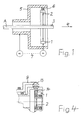
- the device according to the invention is in Fig. 1 only reproduced purely schematically.
- Fig. 1 serves only to explain the principle of construction and operation of the device. More details go from the Fig. 2 to 4 out.
- annular shaft head 1 which is rotatable about its axis and to a first electric motor M 1 - hereinafter "motor M 1" - driven becomes.
- a radially inwardly projecting from the same, also annular Wellerlude 2 is mounted, which preferably consists of stainless steel. It is adjustable within the corrugated head 1 in the radial direction and is used for impressing troughs in an existing metal pipe 3, which is pulled for example in the direction of arrow 4 through the corrugated head 1.
- the Welleremia 2 is arranged eccentrically in the corrugated head 1. It rolls in the circumferential direction around the tube 3 or on the same during operation of the device.
- the tube 3 may for example consist of copper, aluminum or steel, in particular stainless steel.
- the Wellerront 2 may be designed to produce a helical corrugation in the tube 3 as a smooth annular disc. But it can also extend along a screw thread to produce an annular corrugation.
- a holder 5 In the region of the corrugated head 1, a holder 5 is arranged, which is rotatable together with the corrugated head 1 about the axis A. It can be done accordingly Fig. 1 from a second electric motor M2 - in the following "motor 2" - are driven. On the holder 5, an adjusting mechanism 6 is mounted, which acts on the Welleremia 2 and optionally adjusted the same in the radial direction within the corrugated head 1. For such an adjustment, the rotational speed of the second motor M2 is changed briefly, whereby the rotational speed of the holder 5 is changed. The thus changed position of Verstellmechanismusses 6 is thus dependent, for example, on the speed of the holder 5.
- the relative to the tube 3 and the axis A eccentrically arranged Wellerlitis 2 is moved up to the tube 3 until it rests against the surface at one point of its circumference.
- the motors M1 and M2 and the discharge device for the pipe 3 are turned on.
- the motor M 1 rotates the shaft head 1 with the washer plate 2 around the tube 3, which is moved by the trigger mechanism in the direction of the arrow 4 (or opposite).
- the Wellerstrom 2 is now adjusted for example by hand by an operator in the radial direction. As a result, it generates a corrugation extending, for example, helically and transversely to the axial direction of the tube 3 in the same.
- the depth of the corrugation or troughs is measured by a controlling unit or by hand.
- the second motor M2 is turned on, through which the holder 5 is rotated around the axis A at the same speed as the wave head 1.
- the two motors M1 and M2 can be connected to each other in the manner of an electric shaft. This is indicated by the dashed line 7.
- the depth of the corrugation is measured immediately after the start of operation of the device. This can be done with an example optical and / or electrical unit, through which in a connected to the adjusting mechanism 6 control loop, the Weller disk 2 is automatically adjusted in the sense of compensation.
- the adjustment of the Welleremia 2 but can also be done by hand.
- the speed of the second motor M2 is briefly increased or decreased by a signal of the monitoring unit.
- the speed of the second motor M2 can also be adjusted by hand.
- the rotational speed of the holder 5 is then changed by the second motor M2.
- the coupled with the same adjusting mechanism 6 adjusts the Welleremia 2 until the depth of the corrugation corresponds to the predetermined value.
- a preferred embodiment of the device is in Fig. 2 shown.
- the shaft head 1 with Welleremia 2 is here connected to a hollow shaft 8, which is rotated during operation of the device by the first motor M 1 about the axis A.
- the hollow shaft 8 has for receiving the corrugated head 1 at one end of a Fig. 2 apparent Extension.
- the holder 5 is here also designed as a hollow shaft 9 with an extension of the hollow shaft 8 encompassing extension. It is rotatably mounted within the device in a schematically indicated bearing 10 and on the hollow shaft 8 via bearings 1 1 and 12.
- the adjusting mechanism 6 is in the in Fig. 2 illustrated embodiment equipped with a bevel gear 13, with which the hollow shaft 9 is engaged at its enlarged end.
- the bevel gear 13 sits in accordance Fig. 4 on a threaded rod 14 which is rotatably mounted in the corrugated head 1 and connected to the Welleremia 2.
- the bevel gear 13 is advantageously a gear, with which the corresponding equipped with teeth holder 5 meshes.
- the adjustment mechanism 6 may also have a deviating from the illustrated embodiment construction, as long as it is ensured that a change in the rotational speed of the holder 5 and the hollow shaft 9 leads to a radial adjustment of the Wellersay 2.
- the holder 5 or the hollow shaft 9 for actuating the Verstellmechanismusses 6, for example be moved in the axial direction, with unchanged speed of the holder. 5
- a differential gear 15 Between the first motor M1 and the hollow shaft 9 is in the device according to Fig. 2 arranged a differential gear 15, the structure is basically known. Its different gears are stored in a basket 16. By the differential gear 15 ensures that the hollow shaft 9 rotates during operation at the same speed as the hollow shaft 8.
- the basket 16 of the differential gear 15 engages in the illustrated embodiment, an electric servomotor 17 at. If the same is temporarily turned on, for example due to a deviation of the depth of the corrugation in the tube 3 of the predetermined value, the rotational speed of the gear 18 of the differential gear 15 and thus the rotational speed of the hollow shaft 9 is changed. This leads in the above-mentioned sense to the actuation of the bevel gear 13 and thus to the radial adjustment of the Welleractivity 2. Die in Fig. 2 between the individual drive elements and the driven components drawn gears are not provided with reference numerals as known per se machine elements. Instead of the gears also known belts or chains can be used.
- the servomotor 17 can as well as for the second motor M2 after Fig. 1 described, by signals of the Welltiefe supervising or regulating unit or manually switched on and off.
- the basket 16 of the differential gear 15 can be operated in principle without the use of a servomotor by hand, for example by means of a handwheel.
- a second motor M2 is used instead of the differential gear 15, a second motor M2, as it is already in principle Fig. 1 evident.
- the other structure of the device according to Fig. 3 is opposite Fig. 2 unchanged.
- the adjustment of the Welleremia 2 via the bevel gear 13 is effected here by the second motor M2, as for the device according to Fig. 1 is described.
Landscapes
- Engineering & Computer Science (AREA)
- Mechanical Engineering (AREA)
- Shaping Metal By Deep-Drawing, Or The Like (AREA)
- Bending Of Plates, Rods, And Pipes (AREA)
- Investigating Materials By The Use Of Optical Means Adapted For Particular Applications (AREA)
Priority Applications (4)
| Application Number | Priority Date | Filing Date | Title |
|---|---|---|---|
| EP11290404A EP2567762A1 (fr) | 2011-09-12 | 2011-09-12 | Dispositif d'ondulation d'un tuyau métallique |
| US13/586,315 US9283607B2 (en) | 2011-09-12 | 2012-08-15 | Device for corrugating a pipe consisting of metal |
| CN201210332503.XA CN102989853B (zh) | 2011-09-12 | 2012-09-10 | 将金属管制成波形的设备 |
| KR1020120100939A KR20130028885A (ko) | 2011-09-12 | 2012-09-12 | 금속 튜브의 주름 형성 장치 |
Applications Claiming Priority (1)
| Application Number | Priority Date | Filing Date | Title |
|---|---|---|---|
| EP11290404A EP2567762A1 (fr) | 2011-09-12 | 2011-09-12 | Dispositif d'ondulation d'un tuyau métallique |
Publications (1)
| Publication Number | Publication Date |
|---|---|
| EP2567762A1 true EP2567762A1 (fr) | 2013-03-13 |
Family
ID=45033887
Family Applications (1)
| Application Number | Title | Priority Date | Filing Date |
|---|---|---|---|
| EP11290404A Withdrawn EP2567762A1 (fr) | 2011-09-12 | 2011-09-12 | Dispositif d'ondulation d'un tuyau métallique |
Country Status (4)
| Country | Link |
|---|---|
| US (1) | US9283607B2 (fr) |
| EP (1) | EP2567762A1 (fr) |
| KR (1) | KR20130028885A (fr) |
| CN (1) | CN102989853B (fr) |
Cited By (1)
| Publication number | Priority date | Publication date | Assignee | Title |
|---|---|---|---|---|
| ITBO20130313A1 (it) * | 2013-06-20 | 2014-12-21 | Senni Marco | Metodo ed impianto per la produzione di tubi profilati |
Families Citing this family (1)
| Publication number | Priority date | Publication date | Assignee | Title |
|---|---|---|---|---|
| CN117680507A (zh) * | 2023-12-11 | 2024-03-12 | 无锡维思德自动化设备有限公司 | 一种具有智能同步功能的金属软管成型设备 |
Citations (3)
| Publication number | Priority date | Publication date | Assignee | Title |
|---|---|---|---|---|
| JPS60133931A (ja) * | 1983-12-23 | 1985-07-17 | Fujikura Ltd | コルゲ−ト装置 |
| JPH06134527A (ja) * | 1992-10-26 | 1994-05-17 | Fujikura Ltd | コルゲータにおける波高調節方法および装置 |
| EP1084774B1 (fr) | 2000-01-28 | 2003-04-02 | Nexans | Procédé de fabrication continue d'un tube de métal soudé longitudinalement et ondulé er dispositif pour la mise en oeuvre de ce procédé |
Family Cites Families (6)
| Publication number | Priority date | Publication date | Assignee | Title |
|---|---|---|---|---|
| JPS5143825B2 (fr) * | 1973-03-02 | 1976-11-25 | ||
| US4061008A (en) * | 1976-11-10 | 1977-12-06 | Jury Lukich Semenenko | Rolls of a skewed-roll machine for trueing cylindrical metal articles |
| DE3680261D1 (de) * | 1985-08-30 | 1991-08-22 | Hegenscheidt Gmbh Wilhelm | Einrichtung zum fest- bzw. glattwalzen. |
| DE4137275A1 (de) * | 1991-11-13 | 1993-05-19 | Kabelmetal Electro Gmbh | Verfahren zur kontinuierlichen herstellung schraubenlinien- oder ringfoermig gewellter metallrohre |
| WO2007091935A1 (fr) * | 2006-02-06 | 2007-08-16 | Abb Research Ltd | Systeme de pilotage de presse mecanique |
| CN101367100A (zh) * | 2008-08-15 | 2009-02-18 | 芜湖浩达金属制品有限公司 | 铜波纹管螺旋波纹成形设备及其成形工艺 |
-
2011
- 2011-09-12 EP EP11290404A patent/EP2567762A1/fr not_active Withdrawn
-
2012
- 2012-08-15 US US13/586,315 patent/US9283607B2/en not_active Expired - Fee Related
- 2012-09-10 CN CN201210332503.XA patent/CN102989853B/zh not_active Expired - Fee Related
- 2012-09-12 KR KR1020120100939A patent/KR20130028885A/ko not_active Abandoned
Patent Citations (3)
| Publication number | Priority date | Publication date | Assignee | Title |
|---|---|---|---|---|
| JPS60133931A (ja) * | 1983-12-23 | 1985-07-17 | Fujikura Ltd | コルゲ−ト装置 |
| JPH06134527A (ja) * | 1992-10-26 | 1994-05-17 | Fujikura Ltd | コルゲータにおける波高調節方法および装置 |
| EP1084774B1 (fr) | 2000-01-28 | 2003-04-02 | Nexans | Procédé de fabrication continue d'un tube de métal soudé longitudinalement et ondulé er dispositif pour la mise en oeuvre de ce procédé |
Cited By (2)
| Publication number | Priority date | Publication date | Assignee | Title |
|---|---|---|---|---|
| ITBO20130313A1 (it) * | 2013-06-20 | 2014-12-21 | Senni Marco | Metodo ed impianto per la produzione di tubi profilati |
| WO2014203223A1 (fr) * | 2013-06-20 | 2014-12-24 | SENNI, Marco | Procédé et installation pour la production de tubes profilés |
Also Published As
| Publication number | Publication date |
|---|---|
| CN102989853A (zh) | 2013-03-27 |
| KR20130028885A (ko) | 2013-03-20 |
| US9283607B2 (en) | 2016-03-15 |
| US20130205858A1 (en) | 2013-08-15 |
| CN102989853B (zh) | 2016-08-10 |
Similar Documents
| Publication | Publication Date | Title |
|---|---|---|
| EP2524608B2 (fr) | Dispositif de coupe pour une machine de fabrication de tiges de l'industrie de traitement du tabac et procédé de réglage de la position d'une meule ou de chaque meule d'un dispositif de ponçage dans un dispositif de coupe pour une machine de fabrication de tiges de l'industrie de traitement du tabac | |
| DE69811732T2 (de) | Verfahren und vorrichtung zur herstellung einer schnecke | |
| WO2007137561A1 (fr) | Dispositif pour usiner des pièces en forme de barre ou de tuyau par enlèvement de copeaux | |
| DE2937664A1 (de) | Verfahren und vorrichtung zur verlaengerung der lebensdauer einer elastischen verkleidung einer gegenwalze einer drehbaren messerwalze | |
| EP1084774B1 (fr) | Procédé de fabrication continue d'un tube de métal soudé longitudinalement et ondulé er dispositif pour la mise en oeuvre de ce procédé | |
| DE2257981C2 (de) | Vorrichtung zum Durchziehen von Metallrohren mit kreisförmigem Querschnitt durch eine querschnittsverringernde Ziehvorrichtung | |
| DE2458721C3 (de) | Vorrichtung zur Herstellung von Glühlampenwendeln | |
| DE3726239A1 (de) | Falzapparat | |
| EP2500122A1 (fr) | Ebavurage de tuyau, notamment pour tuyaux de systèmes press-fit, ainsi que dispositif d'ébavurage doté d'un tel ébavurage de tuyaux | |
| DE2043983A1 (de) | Verfahren und Vorrichtung zur Her stellung eines unbegrenzt langen Bandes | |
| DE102018131041A1 (de) | Verfahren zur Verzahnbearbeitung eines Werkstücks und Verzahnmaschine | |
| WO2012130361A1 (fr) | Machine pour enlever de la matière sur la périphérie d'un tuyau | |
| WO2013079276A1 (fr) | Dispositif de refendage de bandes continues de matériau en mouvement, en particulier de films plastiques | |
| EP2329896B1 (fr) | Dispositif d'enroulement continu d'un tuyau métallique | |
| AT11798U1 (de) | Rotorrichteinheit zum richten von baustahldraht | |
| CH649013A5 (de) | Vorrichtung zum wellen von rohren. | |
| DE3447183A1 (de) | Trennmaschine fuer kreisbogenfoermige profilstuecke oder profilringe | |
| DE1519897C3 (fr) | ||
| DE3410369A1 (de) | Nachfuehreinrichtung fuer ausfahrbare, in ein werkstueck eingreifende teile | |
| DE19908342C1 (de) | Vorrichtung zum Abschneiden eines Glasstranges | |
| DE1477003B1 (de) | Vorrichtung zum herstellen von drahtschrauben aus steifem draht insbesondere von mänteln für biegsame wellen | |
| DE3033148A1 (de) | Maschine zum zerschneiden von textilmaterialrollen | |
| AT525287B1 (de) | Vorrichtung zum zerlegen von drahtseilen | |
| DE2629571B2 (de) | Verfahren zum Herstellen von Halbtonisschalen, Vorrichtung zum Durchführen des Verfahrens, sowie Halbtonisschale und deren Verwendung | |
| DE1807313A1 (de) | Vorrichtung zum Reinigen von Abwasserleitungen |
Legal Events
| Date | Code | Title | Description |
|---|---|---|---|
| PUAI | Public reference made under article 153(3) epc to a published international application that has entered the european phase |
Free format text: ORIGINAL CODE: 0009012 |
|
| 17P | Request for examination filed |
Effective date: 20120717 |
|
| AK | Designated contracting states |
Kind code of ref document: A1 Designated state(s): AL AT BE BG CH CY CZ DE DK EE ES FI FR GB GR HR HU IE IS IT LI LT LU LV MC MK MT NL NO PL PT RO RS SE SI SK SM TR |
|
| AX | Request for extension of the european patent |
Extension state: BA ME |
|
| RAP1 | Party data changed (applicant data changed or rights of an application transferred) |
Owner name: NEXANS |
|
| 17Q | First examination report despatched |
Effective date: 20171011 |
|
| GRAP | Despatch of communication of intention to grant a patent |
Free format text: ORIGINAL CODE: EPIDOSNIGR1 |
|
| INTG | Intention to grant announced |
Effective date: 20180809 |
|
| STAA | Information on the status of an ep patent application or granted ep patent |
Free format text: STATUS: THE APPLICATION IS DEEMED TO BE WITHDRAWN |
|
| 18D | Application deemed to be withdrawn |
Effective date: 20181220 |