EP2568082A1 - Procédé d'installation d'une structure offshore - Google Patents
Procédé d'installation d'une structure offshore Download PDFInfo
- Publication number
- EP2568082A1 EP2568082A1 EP12006219A EP12006219A EP2568082A1 EP 2568082 A1 EP2568082 A1 EP 2568082A1 EP 12006219 A EP12006219 A EP 12006219A EP 12006219 A EP12006219 A EP 12006219A EP 2568082 A1 EP2568082 A1 EP 2568082A1
- Authority
- EP
- European Patent Office
- Prior art keywords
- buoyancy
- offshore structure
- elements
- floating
- rotation
- Prior art date
- Legal status (The legal status is an assumption and is not a legal conclusion. Google has not performed a legal analysis and makes no representation as to the accuracy of the status listed.)
- Withdrawn
Links
Images


Classifications
-
- E—FIXED CONSTRUCTIONS
- E02—HYDRAULIC ENGINEERING; FOUNDATIONS; SOIL SHIFTING
- E02B—HYDRAULIC ENGINEERING
- E02B17/00—Artificial islands mounted on piles or like supports, e.g. platforms on raisable legs or offshore constructions; Construction methods therefor
- E02B17/02—Artificial islands mounted on piles or like supports, e.g. platforms on raisable legs or offshore constructions; Construction methods therefor placed by lowering the supporting construction to the bottom, e.g. with subsequent fixing thereto
- E02B17/027—Artificial islands mounted on piles or like supports, e.g. platforms on raisable legs or offshore constructions; Construction methods therefor placed by lowering the supporting construction to the bottom, e.g. with subsequent fixing thereto steel structures
-
- B—PERFORMING OPERATIONS; TRANSPORTING
- B63—SHIPS OR OTHER WATERBORNE VESSELS; RELATED EQUIPMENT
- B63B—SHIPS OR OTHER WATERBORNE VESSELS; EQUIPMENT FOR SHIPPING
- B63B35/00—Vessels or similar floating structures specially adapted for specific purposes and not otherwise provided for
- B63B35/003—Vessels or similar floating structures specially adapted for specific purposes and not otherwise provided for for transporting very large loads, e.g. offshore structure modules
-
- E—FIXED CONSTRUCTIONS
- E02—HYDRAULIC ENGINEERING; FOUNDATIONS; SOIL SHIFTING
- E02B—HYDRAULIC ENGINEERING
- E02B17/00—Artificial islands mounted on piles or like supports, e.g. platforms on raisable legs or offshore constructions; Construction methods therefor
- E02B2017/0039—Methods for placing the offshore structure
-
- E—FIXED CONSTRUCTIONS
- E02—HYDRAULIC ENGINEERING; FOUNDATIONS; SOIL SHIFTING
- E02B—HYDRAULIC ENGINEERING
- E02B17/00—Artificial islands mounted on piles or like supports, e.g. platforms on raisable legs or offshore constructions; Construction methods therefor
- E02B2017/0056—Platforms with supporting legs
- E02B2017/0073—Details of sea bottom engaging footing
-
- E—FIXED CONSTRUCTIONS
- E02—HYDRAULIC ENGINEERING; FOUNDATIONS; SOIL SHIFTING
- E02B—HYDRAULIC ENGINEERING
- E02B17/00—Artificial islands mounted on piles or like supports, e.g. platforms on raisable legs or offshore constructions; Construction methods therefor
- E02B2017/0091—Offshore structures for wind turbines
-
- Y—GENERAL TAGGING OF NEW TECHNOLOGICAL DEVELOPMENTS; GENERAL TAGGING OF CROSS-SECTIONAL TECHNOLOGIES SPANNING OVER SEVERAL SECTIONS OF THE IPC; TECHNICAL SUBJECTS COVERED BY FORMER USPC CROSS-REFERENCE ART COLLECTIONS [XRACs] AND DIGESTS
- Y02—TECHNOLOGIES OR APPLICATIONS FOR MITIGATION OR ADAPTATION AGAINST CLIMATE CHANGE
- Y02E—REDUCTION OF GREENHOUSE GAS [GHG] EMISSIONS, RELATED TO ENERGY GENERATION, TRANSMISSION OR DISTRIBUTION
- Y02E10/00—Energy generation through renewable energy sources
- Y02E10/70—Wind energy
- Y02E10/727—Offshore wind turbines
Definitions
- the invention relates to a method for installing an offshore structure according to the preamble of claim 1.
- offshore structures in particular foundation structures for wind turbines
- the transport of offshore structures is usually carried out by means of ships or pontoons on which the offshore structures are transported in a load-bearing manner.
- the offshore structures are lifted by means of suitable lifting devices, in particular cranes, from the ship or pontoon and deposited in the water. Heavy duty cranes are required for this operation. Transporting and depositing the offshore structure is made more difficult and costly.
- Object of the present invention is therefore to provide a method for installing an offshore structure, whereby the installation of the offshore structure can be simple, inexpensive and secure.
- the object is achieved by a method with the measures of claim 1.
- the method according to the invention for installing an offshore structure is characterized in that the offshore structure in the horizontal state is transported floating to the installation site and erected by lowering the buoyancy before lowering.
- the offshore structure is therefore placed in the underlying manufacturing situation into the water.
- the offshore structure In this recumbent state, the offshore structure is floated floating in the water without ships or pontoons carrying the offshore structure to the installation site.
- the draft of the offshore structure is low in the lying position.
- the offshore structure is then self-aligning by shifting the buoyancy of the same by eliminating the need for further mechanical lifting means such as cranes.
- a floating axis of rotation of the offshore structure is formed by at least one buoyancy element, preferably a longitudinal axis thereof, wherein the offshore structure rotates about the floating axis of rotation during the preferably automatic erection.
- the automatic erection is achieved by a shift or a change in the buoyancy of the offshore structure.
- a mass imbalance arises relative to the floating axis of rotation. This mass imbalance leads to an autonomous turning and erecting of the offshore structure about the floating axis of rotation, wherein an underwater part of the offshore structure is lowered into the water and an overwater part of the offshore structure is lifted out of the water.
- the at least one, the floating axis of rotation forming buoyancy element of rigid, preferably cylindrical, hollow bodies is formed.
- the use of hollow bodies for the at least one buoyant element that forms the floating axis of rotation is particularly advantageous, since the geometry of the hollow body does not change when the hollow body rotates about the floating axis of rotation when erecting the offshore structure.
- the at least one, the floating axis of rotation forming buoyancy element, preferably the cylindrical hollow body is assigned to the offshore structure, that the longitudinal axis is aligned above the center of mass of the offshore structure and perpendicular to the longitudinal axis of the offshore structure.
- this extends through the offshore structure, such that the longitudinal axis of a cylindrical hollow body is positioned with respect to the longitudinal axis of the offshore structure above the center of gravity of the offshore structure.
- the buoyancy elements forming the floating axis of rotation are two cylindrical hollow bodies, these two opposite outer sides are associated with the offshore structure such that the longitudinal axes of the cylindrical hollow bodies coincide with the floating axis of rotation and they are viewed in the direction of the longitudinal axis of the offshore structure is above the center of gravity of the offshore structure.
- the advantage of such a positioning of the at least one buoyancy element, which forms the floating axis of rotation, above the center of gravity is that in the weight shift or in the displacement of the lift, the offshore structure rotates about the floating axis of rotation, that a lower part of the offshore structure ins Water dips and an upper part is raised above the water.
- the offshore structure is assigned at least one additional buoyancy element.
- This at least one additional buoyancy element is positioned in the direction of the longitudinal axis of the offshore structure at a distance from the at least one buoyancy element forming the floating axis of rotation.
- the at least one additional buoyancy element can be coupled or integrated into the offshore structure in any desired manner in the direction of the longitudinal axis of the offshore structure.
- similarly designed additional buoyancy elements in the direction of the longitudinal axis of the offshore structure are assigned to the lower part, the later underwater part, of the offshore structure on opposite outer sides.
- buoyancy elements in the direction of the longitudinal axis of the offshore structure seen in the upper part (overwater part) of the offshore structure are assigned to opposite outer sides.
- the additional buoyancy elements can be aligned at least partially flexible. Such positioning of the buoyancy elements parallel to the longitudinal axis of the offshore structure results in stabilization of the same during horizontal floating transport. This prevents the offshore structure from tilting or turning uncontrollably during transport.
- the buoyancy of the offshore structure is changed by flooding and / or distancing the buoyancy elements.
- the flooding can take place automatically by the supply of a liquid, preferably of seawater, into the respective buoyancy element.
- Lenzen the buoyancy elements can be done by bilge pumps or blowing compressed air.
- the buoyancy of the buoyancy elements can also be changed by the admission or omission of compressed air.
- the method further provides that, for transporting the offshore structure, the buoyancy of the buoyancy elements is changed by flooding and / or limiting the buoyancy elements.
- the buoyancy elements are completely filled with air so that the offshore structure is in the water and much of the offshore structure is lifted out of the water. Due to this increased buoyancy, the offshore structure is completely or mostly lifted out of the water. It turns out to be particularly advantageous for the transport of the offshore structure, if only a small part of the offshore structure is below the water surface, since the water resistance of the offshore structure during transport is minimized and the transport of the offshore structure becomes less dependent on the water depth.
- the offshore structure floats in the water by the buoyancy of the buoyancy elements and is moved by watercraft, in particular towed to the foundation site.
- the hauling of the offshore structure to the foundation site is preferably done with tugs or similar vessels.
- the buoyancy of the at least one part to be lowered, in particular the underwater part of the offshore structure is reduced for the preferably automatic raising of the offshore structure, so that by reducing the buoyancy the underwater part of the offshore structure with the flooded additional buoyancy element is lowered into the water becomes.
- the lift of the at least one buoyancy element forming the floating axis of rotation is reduced for lowering the erected offshore structure at the place of foundation. This is done preferably by ballasting with seawater, whereby a slow and targeted lowering of the offshore structure is ensured.
- a further advantageous embodiment of the method according to the invention is that by varying the buoyancy of the at least one additional buoyancy element, which is located above the floating axis of rotation after raising, the lowering depth of the offshore structure of the sea depth is varied accordingly.
- the buoyancy can be changed according to the requirements by targeted lashing and flooding in order to adapt the draft of the erected offshore structure to the conditions at the foundation site.
- a particularly advantageous embodiment of the invention provides that the buoyancy of the offshore structure is produced by buoyancy elements which can be fastened to the offshore structure, preferably detachably fastened, and / or by buoyancy elements integrated in the offshore structure.
- Buoyancy elements which can be fastened or detachably fastened to the offshore structure are particularly advantageous, since they can be fastened and reused at any desired positions of the offshore structure.
- at least some buoyancy elements are integrated into the offshore structure itself. This could be realized, for example, by the formation of buoyancy chambers in selected hollow pipes of the offshore structure. This eliminates the need for additional buoyancy elements or the number of the same can be reduced.
- Such buoyancy elements, which are formed by chambers in the tube structure of the offshore structure can be controlled via pumps and valves in such a way that the buoyancy of these chambers and thus the buoyancy of the offshore structure can be changed by lashing and flooding.
- the buoyancy of the buoyancy elements is controlled such that in addition to the automatic erection an automatic variation of the floating position and / or the lowering of the offshore structure on the seabed are possible.
- the individual buoyancy elements on pumps, valves and sensors through which can be controlled by flooding and limiting the individual buoyancy elements their buoyancy targeted individually and coordinated.
- buoyancy of those additional buoyancy elements which are inflatable buoyancy elements is controlled by the degree of gas filling of the buoyancy elements is varied.
- Inflatable buoyancy elements are particularly advantageous since they have a very low dead weight in the non-inflated state and are particularly space-saving. As a result, they can be installed very flexibly at different positions of the offshore structure.
- inflatable buoyancy elements are particularly advantageous when lowering the offshore structure, since due to the water pressure acts on the inflatable buoyancy elements from the outside, the gas is pushed out of the buoyancy elements particularly fast and energy efficient.
- the submerged volume of the at least one buoyancy element forming the floating axis of rotation remains almost the same.
- rotation is particularly uniform.
- the erection can be controlled very well. In particular, such an unforeseen placement of the offshore structure on the seabed can be avoided.
- the foundation structure 10 shown in the figures has a grid-like tube structure 11.
- An outwardly projecting out of the water upper part 13 of the tube structure 11 is provided with a serving as a connection part for the tower, for example, a wind turbine intermediate piece 28.
- a lower part 14 of the tube structure 11, which is under water after installation of the foundation structure 10, is provided with grooved pegs 30 which are introduced into ramming piles (not shown) previously introduced into the seabed.
- the lower part 14 of the pipe structure 11 may also be provided with pile sleeves or other means of foundation.
- a centrally extending through the foundation structure 10 longitudinal axis 15 is perpendicular to installed foundation structure 10, then represents a quasi-perpendicular longitudinal central axis.
- On the longitudinal axis 15 is a center of gravity 16 of the foundation structure 10. Because the tube structure 11 tapers towards the upper part 13, the Center of mass 16 slightly below half the height of the pipe structure 11.
- the foundation structure 10 is provided in the illustrated embodiment with six buoyancy elements. Two of the buoyancy elements are fixed permanently or detachably as cylindrical buoyancy elements 17 on the outer sides 18 of the tube structure 11.
- the cylindrical buoyancy elements 17 are fastened to the outer sides 18 of the foundation structure 10 such that their longitudinal center axes 19 lie on a common line which forms a floating axis of rotation 20 of the foundation structure 10. It is also conceivable that the buoyancy elements 17 have a different shape.
- This floating axis of rotation 20 formed by the cylindrical buoyancy elements 17 extends at a right angle to the longitudinal axis 15 of the foundation structure 10 and intersects this longitudinal axis 15 in the direction of the upper part 13 of the foundation structure 10 above the center of gravity 16.
- the cylindrical buoyancy elements 17 are designed as gestaltsunver primaryliche, rigid hollow body.
- the buoyancy of the cylindrical buoyancy elements 17 can be changed by lashing or flooding.
- the flooding can be done by closable valves that allow a targeted entry of seawater in the buoyancy elements 17. For latency, the seawater in the buoyancy elements 17 is pushed out by compressed air.
- two further additional buoyancy elements are assigned to the lower part 14 of the foundation structure 10.
- These two additional buoyancy elements 21 on the lower part 14 of the foundation structure 10 are preferably releasably attached to the outer sides 18 of the foundation structure 10.
- Two further additional buoyancy elements 22 are also preferably detachably attached to the upper part 13 of the foundation structure 10.
- the additional buoyancy elements 21 and 22 are arranged at a distance from the longitudinal axis 15 of the foundation structure 10 at the outer sides 18 of the pipe structure 11.
- the additional buoyancy elements 21, 22 may have any shape. They are preferably cuboid or cylindrical. However, it is particularly advantageous if the additional buoyancy elements 21, 22 have a longitudinal axis which is aligned parallel to the longitudinal axis 15 of the foundation structure 10. The additional buoyancy elements 21 and 22 are associated parallel to the longitudinal axis 15 of the foundation structure 10 of the same.
- the additional buoyancy elements 21, 22 are flexible in contrast to their buoyancy elements 17, so collapsible.
- the buoyancy of the additional buoyancy elements 21, 22 can be increased continuously by filling with compressed air. By releasing the compressed air, the buoyancy of the additional buoyancy elements 21, 22 can be reduced.
- the buoyancy elements 21, 22 can also be completely removed from the foundation structure in their state filled with compressed air or in their emptied state. But you can also be designed as a rigid hollow body.
- the invention is not limited to the embodiment or arrangement of the buoyancy elements 17, 21, 22 shown.
- the buoyancy elements 21, 22 may be arranged fixed or detachable at arbitrary locations of the upper part 13 and the lower part 14 of the pipe structure 11. It is also conceivable, in particular, to integrate the additional buoyancy elements 21, 22 into the tube structure 11, in that watertight sections of the tubes for forming the tube structure 11 are formed as floatable and deflectable hollow bodies. Also, in particular, the additional buoyancy elements 21, 22 may have any desired shapes. It is also conceivable that due to the buoyancy elements 17 arranged above the center of gravity 16 of the foundation structure 10, only additional buoyancy elements 21 are associated with the lower part 14 of the pipe structure 11. The additional buoyancy elements 22 on the upper part 13 of the foundation structure 10 can then be omitted.
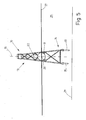
- the inventive method is described below with reference to Fig. 3 to 5 explained in more detail:
- the foundation structure 10 is produced in a lying position, that is to say with a longitudinal axis 15 extending parallel or nearly parallel to the land 24.
- the finished foundation structure 10 is left in a conventional manner from the land 24 into the water 25. A difficult and dangerous erection of the foundation structure 10 on land 24 is not necessary.
- the buoyancy elements 17, 21 and 22 are completely filled with air, the buoyancy force of the foundation structure 10 is greater than its weight, whereby the foundation structure 10 floats in the water 25.
- the draft of the foundation structure 10 can be adapted to the needs. Because buoyant elements 21, 22 are fastened to both the lower part 14 and the upper part 13 of the foundation structure 10, the underlying foundation structure 10 floats stably in the water 25.
- the horizontal foundation structure 10 is floatingly transported in the water 25. Due to the buoyancy generated by the buoyancy elements 17, 21, 22, no transport means carrying the foundation structure 10, such as a pontoon or a barge, is necessary. The foundation structure 10 floats itself in the water without further aids.
- the foundation structure 10 In order to transport the foundation structure 10 from the harbor to the foundation site, the foundation structure 10 is floated in the horizontal state by at least one tractor 26, in the shown embodiment two tractors 26.
- FIG. 4 is shown how the foundation structure 10 is erected automatically at the foundation.
- compressed air from the additional buoyancy elements 21 at the lower part 14 of the foundation structure 10 is correspondingly discharged or the buoyancy elements 21 are flooded with water or removed from the foundation structure 10.
- the buoyancy force at the lower part 14 of the foundation structure 10 is reduced by the fact that now at the lower part 14, the weight of the Founding structure 10 is greater than their buoyancy, the lower part 14 of the foundation structure 10 lowers by itself, so automatically, and without additional aids into the water 25 off.
- Fig. 5 It is shown how the upright foundation structure 10 is lowered at the foundation site.
- the foundation structure 10 is lowered by targeted flooding of the buoyancy elements 17 and optionally the additional buoyancy elements 22 at the upper part 13 of the foundation structure 10 and anchored during or after lowering in a conventional manner on the seabed in already pre-installed space piles.
- this is done with the grooved peg 30.
- the foundation structure 10 can also be anchored to the seafloor with other foundation means, such as, for example, pile pods.
- the buoyancy of the foundation structure 10 can be increased again by lessening the buoyancy elements 17, 21, 22, so that the foundation structure 10 rises from the water 25 and, for example, transports it to the harbor again after being automatically transferred to a lying position can be.
Landscapes
- Engineering & Computer Science (AREA)
- General Engineering & Computer Science (AREA)
- Mechanical Engineering (AREA)
- Civil Engineering (AREA)
- Structural Engineering (AREA)
- Foundations (AREA)
- Wind Motors (AREA)
Applications Claiming Priority (2)
| Application Number | Priority Date | Filing Date | Title |
|---|---|---|---|
| DE102011112786 | 2011-09-09 | ||
| DE102011116203A DE102011116203A1 (de) | 2011-09-09 | 2011-10-15 | Verfahren zur Installation einer Offshorestruktur |
Publications (1)
| Publication Number | Publication Date |
|---|---|
| EP2568082A1 true EP2568082A1 (fr) | 2013-03-13 |
Family
ID=47022438
Family Applications (1)
| Application Number | Title | Priority Date | Filing Date |
|---|---|---|---|
| EP12006219A Withdrawn EP2568082A1 (fr) | 2011-09-09 | 2012-09-03 | Procédé d'installation d'une structure offshore |
Country Status (2)
| Country | Link |
|---|---|
| EP (1) | EP2568082A1 (fr) |
| DE (1) | DE102011116203A1 (fr) |
Cited By (3)
| Publication number | Priority date | Publication date | Assignee | Title |
|---|---|---|---|---|
| WO2018151594A1 (fr) | 2017-02-14 | 2018-08-23 | Marine Innovators B.V. | Structure d'installation d'éolienne en mer |
| CN115652977A (zh) * | 2022-10-21 | 2023-01-31 | 盛东如东海上风力发电有限责任公司 | 漂浮式单桩基础及其安装方法 |
| WO2024235407A1 (fr) * | 2023-05-12 | 2024-11-21 | Phoenix Ii A/S | Procédé, appareil et système de manœuvre de monopieu |
Citations (4)
| Publication number | Priority date | Publication date | Assignee | Title |
|---|---|---|---|---|
| US3036438A (en) * | 1958-04-04 | 1962-05-29 | Jersey Prod Res Co | Caisson with float releasably attached |
| US3054267A (en) * | 1957-05-29 | 1962-09-18 | Petroleum Mortgage Company | Method of and means for launching and erecting offshore structures |
| US3496897A (en) * | 1968-05-17 | 1970-02-24 | Texaco Inc | Apparatus for transporting a floatable marine platform |
| US4135842A (en) * | 1978-01-13 | 1979-01-23 | Brown & Root, Inc. | Method for transporting and erecting offshore towers |
-
2011
- 2011-10-15 DE DE102011116203A patent/DE102011116203A1/de not_active Withdrawn
-
2012
- 2012-09-03 EP EP12006219A patent/EP2568082A1/fr not_active Withdrawn
Patent Citations (4)
| Publication number | Priority date | Publication date | Assignee | Title |
|---|---|---|---|---|
| US3054267A (en) * | 1957-05-29 | 1962-09-18 | Petroleum Mortgage Company | Method of and means for launching and erecting offshore structures |
| US3036438A (en) * | 1958-04-04 | 1962-05-29 | Jersey Prod Res Co | Caisson with float releasably attached |
| US3496897A (en) * | 1968-05-17 | 1970-02-24 | Texaco Inc | Apparatus for transporting a floatable marine platform |
| US4135842A (en) * | 1978-01-13 | 1979-01-23 | Brown & Root, Inc. | Method for transporting and erecting offshore towers |
Cited By (3)
| Publication number | Priority date | Publication date | Assignee | Title |
|---|---|---|---|---|
| WO2018151594A1 (fr) | 2017-02-14 | 2018-08-23 | Marine Innovators B.V. | Structure d'installation d'éolienne en mer |
| CN115652977A (zh) * | 2022-10-21 | 2023-01-31 | 盛东如东海上风力发电有限责任公司 | 漂浮式单桩基础及其安装方法 |
| WO2024235407A1 (fr) * | 2023-05-12 | 2024-11-21 | Phoenix Ii A/S | Procédé, appareil et système de manœuvre de monopieu |
Also Published As
| Publication number | Publication date |
|---|---|
| DE102011116203A1 (de) | 2013-03-14 |
Similar Documents
| Publication | Publication Date | Title |
|---|---|---|
| EP2360373B1 (fr) | Installation offshore, fondation d'une installation offshore et procédé d'établissement d'une installation offshore | |
| EP2436593B1 (fr) | Bateau et procédé de transport et d'établissement de structures offshore | |
| DE2345274A1 (de) | Hebbare hochseeplattform | |
| EP2539219B1 (fr) | Dispositif pour le transport et l'installation d'un agencement d'une éolienne offshore comprenant une embase et procédé pour le transport et l'installation d'un tel agencement muni d'une embase | |
| DE102008046359A1 (de) | Vorrichtung zum Transport und Installieren von zumindest eine Flachgründung umfassende Anordnung einer Offshore-Windenergieanlage sowie Verfahren zum Transport und zur Installation einer solchen Flachgründung mit Mast | |
| DE10101405A1 (de) | Off-Shore-Windkraftanlage | |
| EP1673536A1 (fr) | Fondation pour eolienne en mer | |
| EP1234978B1 (fr) | Eolienne marine | |
| DE2316667A1 (de) | Versenkbare konstruktion | |
| EP3428345A1 (fr) | Fondation pour une éolienne en mer | |
| DE102010026711A1 (de) | Halbtaucher zum Transport und/oder Ausführen von Arbeiten auf See sowie Verfahren zur Positionierung offshore | |
| DE20100588U1 (de) | Off-Shore-Windkraftanlage | |
| WO2018054532A1 (fr) | Ouvrage destiné à être érigé à la surface d'étendues d'eau et procédé pour son érection | |
| EP2036815B1 (fr) | Procédé d'installation et de démontage d'une structure de fondation ainsi que structure de fondation et flotteur | |
| EP2036813B1 (fr) | Structure de fondation ainsi que son procédé de fabrication | |
| EP2568082A1 (fr) | Procédé d'installation d'une structure offshore | |
| EP2623674A1 (fr) | Infrastructure pour une plateforme offshore et procédé d'installation d'une telle infrastructure | |
| DE102007002314A1 (de) | Installation von Offshore-Windenergieanlagen | |
| DE2457536C3 (de) | Verfahren zum Transport und zum Absetzen einer Offshore-Plattform auf der Meeressohle sowie Offshore-Plattform | |
| EP2623675A1 (fr) | Partie supérieure d'une plateforme offshore et procédé d'installation d'une telle partie supérieure d'une plateforme | |
| EP3922845B1 (fr) | Ouvrage en mer flottant et son procédé d'installation | |
| DE20103421U1 (de) | Off-Shore-Windkraftanlage | |
| DE102008017785A1 (de) | Fundament für ein Offshorebauwerk und Verfahren zum Erstellen eines Fundaments eines Offshorebauwerks | |
| WO2015052295A1 (fr) | Fondation gravitaire | |
| EP3255211B1 (fr) | Structure de pont élévateur |
Legal Events
| Date | Code | Title | Description |
|---|---|---|---|
| PUAI | Public reference made under article 153(3) epc to a published international application that has entered the european phase |
Free format text: ORIGINAL CODE: 0009012 |
|
| AK | Designated contracting states |
Kind code of ref document: A1 Designated state(s): AL AT BE BG CH CY CZ DE DK EE ES FI FR GB GR HR HU IE IS IT LI LT LU LV MC MK MT NL NO PL PT RO RS SE SI SK SM TR |
|
| AX | Request for extension of the european patent |
Extension state: BA ME |
|
| STAA | Information on the status of an ep patent application or granted ep patent |
Free format text: STATUS: THE APPLICATION IS DEEMED TO BE WITHDRAWN |
|
| 18D | Application deemed to be withdrawn |
Effective date: 20130914 |