EP2568087A2 - Sanitärarmatur - Google Patents
Sanitärarmatur Download PDFInfo
- Publication number
- EP2568087A2 EP2568087A2 EP12005836A EP12005836A EP2568087A2 EP 2568087 A2 EP2568087 A2 EP 2568087A2 EP 12005836 A EP12005836 A EP 12005836A EP 12005836 A EP12005836 A EP 12005836A EP 2568087 A2 EP2568087 A2 EP 2568087A2
- Authority
- EP
- European Patent Office
- Prior art keywords
- outlet
- sealing surfaces
- valve
- sanitary fitting
- changeover valve
- Prior art date
- Legal status (The legal status is an assumption and is not a legal conclusion. Google has not performed a legal analysis and makes no representation as to the accuracy of the status listed.)
- Granted
Links
Images
Classifications
-
- E—FIXED CONSTRUCTIONS
- E03—WATER SUPPLY; SEWERAGE
- E03C—DOMESTIC PLUMBING INSTALLATIONS FOR FRESH WATER OR WASTE WATER; SINKS
- E03C1/00—Domestic plumbing installations for fresh water or waste water; Sinks
- E03C1/12—Plumbing installations for waste water; Basins or fountains connected thereto; Sinks
- E03C1/30—Devices to facilitate removing of obstructions in waste-pipes or sinks
-
- F—MECHANICAL ENGINEERING; LIGHTING; HEATING; WEAPONS; BLASTING
- F16—ENGINEERING ELEMENTS AND UNITS; GENERAL MEASURES FOR PRODUCING AND MAINTAINING EFFECTIVE FUNCTIONING OF MACHINES OR INSTALLATIONS; THERMAL INSULATION IN GENERAL
- F16K—VALVES; TAPS; COCKS; ACTUATING-FLOATS; DEVICES FOR VENTING OR AERATING
- F16K11/00—Multiple-way valves, e.g. mixing valves; Pipe fittings incorporating such valves
- F16K11/02—Multiple-way valves, e.g. mixing valves; Pipe fittings incorporating such valves with all movable sealing faces moving as one unit
- F16K11/04—Multiple-way valves, e.g. mixing valves; Pipe fittings incorporating such valves with all movable sealing faces moving as one unit comprising only lift valves
- F16K11/044—Multiple-way valves, e.g. mixing valves; Pipe fittings incorporating such valves with all movable sealing faces moving as one unit comprising only lift valves with movable valve members positioned between valve seats
- F16K11/0445—Bath/shower selectors
-
- E—FIXED CONSTRUCTIONS
- E03—WATER SUPPLY; SEWERAGE
- E03C—DOMESTIC PLUMBING INSTALLATIONS FOR FRESH WATER OR WASTE WATER; SINKS
- E03C2201/00—Details, devices or methods not otherwise provided for
- E03C2201/30—Diverter valves in faucets or taps
Definitions
- Sanitary fittings of the above type are available in a variety of designs and a large number on the market; a printed proof for this does not need it.
- the means in the outlet, which separate the local different waterways, formed by cast partitions formed by cast partitions. This means that several cores are generally needed to make the spout, which increases the manufacturing overhead.
- the molded partitions are partially defective, so that there are leaks between the different waterways to be separated.
- Object of the present invention is to provide a sanitary fitting of the type mentioned in such a way that it can be produced cheaper and with fewer errors.
- the task of separating the different waterways in the outlet is taken over by the diverter valve itself.
- This has the advantage that the complicated shape design that is necessary to achieve the Wasserwegtrennung, takes place on the diverter valve, the housing can be injected in general as a plastic part in a complicated form cost.
- the risk of leakage through the diverter valve is virtually eliminated.
- an impairment of the flow cross-sections of the diverter valve is avoided because in the cast spout no partitions are in the way.
- the sealing surfaces of the changeover valve and / or on the inner surfaces of the outlet are formed on raised ribs. This improves the sealing function and facilitates, where necessary, a mechanical processing of the sealing surfaces, as it is particularly useful on the inner surfaces of the spout.
- At least one seal should be located between the sealing surfaces of the diverter valve and the sealing surfaces on the inner surface of the spout.
- the diverter valve may include a slidable shuttle which in a first position bears against a first valve seat formed in the housing of the diverter valve and in a second position bears against a second valve seat provided at the shower port designed as a port nipple.
- the connection nipple can be used to attach the diverter valve.
- All seals may be formed as one-piece molding, which reduces the cost of manufacturing and simplifies storage.
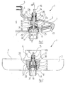
- the tub filling fitting 1 has a housing 2 produced by casting, to which an outlet 3 is integrally formed.
- a hollow cylindrical collar 4 which has an upper mounting hole 5.
- This control cartridge is not shown in the drawing. Every design is conceivable here. Suffice it to know that escape from this control cartridge water and can flow into the interior 7 of the outlet 3.
- the interior 7 of the outlet 3 communicates over a large area with the interior 6 of the remaining housing 2, as in particular the FIG. 1 can be seen.
- the outlet 3 of the tub filling fitting 1 is pierced in the lower wall and the upper wall of coaxial circular cross-section openings, in particular holes 8, 9.
- These openings 8, 9 are used in a manner described in more detail below for mounting a diverter valve, which in total carries the reference numeral 10, and a connection nipple 11 which can be connected to a shower (not shown), in particular via a shower hose with a hand shower ,
- the changeover valve 10 has a Umstellventilgephase 12, which has approximately in the middle of its height formed by a circumferential step first valve seat 13.
- an actuating rod 15 is guided displaceably.
- This actuating rod 15th carries at its lower, lying below the first valve seat 13 end a shuttle 16.
- a compression spring 17 which is clamped between a step of the bore 14 and the shuttle 16, pushes the shuttle 16 down.
- the actuating rod 15 projects upwards out of the diverter valve 10 and is provided with a handle (not shown) in the final assembly of the sanitary fitting 1.
- the space in the changeover valve 10, which is located below the first valve seat 13, is connected via a first window 18 to that area 7a of the interior 7 of the outlet 3, which communicates directly with the interior 6 of the remaining housing 2.
- the diverter valve 10 above the first valve seat 13 has a second window 19, which, however, apart from the height offset, diametrically opposite the first window 18 and lying above the first valve seat 13 interior of the changeover valve 10 with the portion 7b of the interior. 7 connects, which communicates with the outlet opening 20 of the outlet 3.
- the areas 7a and 7b of the interior 7 of the outlet 3 are separated from each other by the diverter valve 10 in a manner described below, that a water flow between these areas can be done only by the Umstellventil 10, but not outside of this.
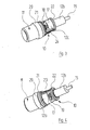
- FIGS. 2 to 4 show the main portion 12a of the change-over valve 10 below the first window 18 carries a first radially projecting Ring collar 21 and above the second window 19, a second, also radially projecting annular collar 22.
- the two annular collars 21, 22 are connected by likewise integrally formed on the main region 12a and each on both sides of the window 18, 19 webs 23, 24 with each other.
- the radius of the upper annular collar 22 is slightly less than that of the lower annular collar 21, so that the webs 23, 24 are not exactly parallel to the axis but are slightly inclined towards each other upwards. This is also the FIG. 2 refer to.
- the interior 7 of the spout 3 has no partitions which would separate different waterways within the spout 3 from each other. Rather, the boundary walls of the interior 7 are largely smooth. However, an exception form two provided on opposite side walls of the interior 7 slightly raised ribs 26, 27, whose inwardly facing end faces are machined so that they are suitable as sealing surfaces 37, 38. The ribs 26, 27 incline toward one another at the same angle and in the same direction as the webs 23, 24 of the changeover valve 10 or the areas of the seal 25 extending in these webs 23, 24.
- the diverter valve 10 is mounted from below, so through the opening 8 in the lower wall of the outlet 3 in the outlet, the neck 12 b is passed through the opening 9 in the upper wall of the outlet 3 with the interposition of a decorative hood 28.
- the region of the seal 25, which runs in the lower annular collar 21, lies against the peripheral wall of the opening 8 serving as sealing surface 39, the region of the seal 25 which runs in the upper annular collar 22 on a step serving as sealing surface 40 Opening 9 and the areas extending in the webs 23 and 24, on the sealing surfaces 37, 38 of the ribs 26, 27 of the inner wall of the outlet 3 at. In this way, the above-mentioned separation of the two areas 7a, 7b of the interior 7 of the outlet 3 is achieved by the diverter valve 10.
- connection nipple 11 is screwed with an external thread 29 in the lower region of the opening 8 in the lower wall of the outlet 3.
- a reduced diameter neck 30 at the upper end of the connecting nipple 11 engages from below into the Umstellventilgephase 12 and forms above a second valve seat 31, which also cooperates with the shuttle 16.
- An annular end face 32 of the connecting nipple 11 which surrounds the neck 30 bears against the reversing valve housing 12 from below and pushes it upward in the assembled state of the connecting nipple 11.
- a seal which is not provided to relieve the drawing with its own reference number, is located in the annular end face 32 and provides a seal of the connecting nipple 11 against the Umstellventilgephase 12.
Landscapes
- Engineering & Computer Science (AREA)
- General Engineering & Computer Science (AREA)
- Mechanical Engineering (AREA)
- Environmental & Geological Engineering (AREA)
- Health & Medical Sciences (AREA)
- Life Sciences & Earth Sciences (AREA)
- Hydrology & Water Resources (AREA)
- Public Health (AREA)
- Water Supply & Treatment (AREA)
- Multiple-Way Valves (AREA)
- Bathtubs, Showers, And Their Attachments (AREA)
- Nozzles (AREA)
Abstract
Description
- Die Erfindung betrifft eine Sanitärarmatur mit
- a) einem gegossenen Auslauf, der eine Wasserauslauföffnung aufweist;
- b) einem an dem Auslauf angeordneten Brauseanschluss;
- c) einem in dem Auslauf angeordneten handbetätigten Umstellventil, welches wahlweise eine Wasserströmung zu dem Wasserauslauf oder zu dem Brauseanschluss freigibt;
- d) Mitteln im Auslauf, welche die verschiedenen Wasserwege im Auslauf voneinander trennen.
- Sanitärarmaturen der oben genannten Art sind in unterschiedlichster Ausgestaltung und großer Anzahl auf dem Markt; eines druckschriftlichen Nachweises hierfür bedarf es nicht. Bei diesen bekannten Sanitärarmaturen werden die Mittel im Auslauf, welche die dortigen verschiedenen Wasserwege voneinander trennen, durch angegossene Trennwände gebildet. Dies bedeutet, dass zur Herstellung des Auslaufs im Allgemeinen mehrere Kerne benötigt werden, was den Herstellungsaufwand erhöht. Außerdem sind die angegossenen Trennwände teilweise fehlerhaft, so dass sich Leckagen zwischen den verschiedenen voneinander zu trennenden Wasserwegen ergeben.
- Aufgabe der vorliegenden Erfindung ist es, eine Sanitärarmatur der eingangs genannten Art so auszugestalten, dass sie preiswerter und mit weniger Fehlern hergestellt werden kann.
- Diese Aufgabe wird erfindungsgemäß dadurch gelöst, dass
- e) die Mittel zur Trennung der Wasserwege von dem Umstellventil selbst gebildet sind, das hierzu an seiner Außenseite mit Dichtflächen versehen ist, die mit Dichtflächen an der Innenfläche des Auslaufs zusammenwirken.
- Erfindungsgemäß wird also die Aufgabe der Trennung der verschiedenen Wasserwege in dem Auslauf von dem Umstellventil selbst übernommen. Dies hat den Vorteil, dass die kompliziertere Formgestaltung, die zur Erzielung der Wasserwegtrennung erforderlich ist, an dem Umstellventil erfolgt, dessen Gehäuse im Allgemeinen als Kunststoffteil auch in komplizierter Form kostengünstig gespritzt werden kann. Darüber hinaus ist die Gefahr von Leckagen durch das Umstellventil hindurch praktisch eliminiert. Ausserdem wird eine Beeinträchtigung der Durchflussquerschnitte des Umstellventils vermieden, da im gegossenen Auslauf keine Trennwände mehr im Wege stehen.
- Zweckmäßigerweise sind die Dichtflächen des Umstellventils und/oder an den Innenflächen des Auslaufs an erhabenen Rippen ausgebildet. Dies verbessert die Dichtfunktion und erleichtert, wo dies erforderlich ist, eine mechanische Bearbeitung der Dichtflächen, wie sie insbesondere an den Innenflächen des Auslaufs zweckmäßig ist.
- Zwischen den Dichtflächen des Umstellventils und den Dichtflächen an der Innenfläche des Auslaufs sollte mindestens eine Dichtung angeordnet sein.
- Besonders vorteilhaft ist, wenn zumindest zwei Dichtflächen des Umstellventils in einer Richtung aufeinander zukonvergieren und die mit diesen zusammenwirkenden Dichtflächen an der Innenfläche des Auslaufs eine entsprechende Konvergenz aufweisen. Grund hierfür ist, dass das Umstellventil bei der Montage der Sanitärarmatur im Allgemeinen in axialer Richtung in den Auslauf eingeschoben wird. Wenn Dichtflächen des Umstellventils und die entsprechenden Dichtflächen an der Innenfläche des Auslaufs in dieser Richtung aufeinander zukonvergieren, können die Dichtflächen bzw. die zwischen diesen liegende Dichtung zuverlässig angedrückt werden, was die Dichtwirkung verbessert.
- Das Umstellventil kann einen verschiebbaren Doppelventilkegel umfassen, der in einer ersten Position an einem ersten Ventilsitz anliegt, der in dem Gehäuse des Umstellventils ausgebildet ist, und in einer zweiten Position an einem zweiten Ventilsitz anliegt, der an dem als Anschlussnippel gestalteten Brauseanschluss vorgesehen ist. Die Verwendung des Anschlussnippels als zweiter Ventilsitz vereinfacht die Formgebung des Gehäuses des Umstellventils. Zudem kann der Anschlussnippel der Befestigung des Umstellventils dienen.
- Zweckmäßig ist ferner, wenn an der Außenmantelfläche des Gehäuses des Umstellventils in axialem Abstand voneinander zwei Ringbünde ausgebildet sind, die mit Hilfe einer Dichtung eine Abdichtung des Umstellventils gegen die obere bzw. untere Wand des Auslaufs bewirken.
- Alle Dichtungen können als einstückiges Formteil ausgebildet sein, was die Herstellung verbilligt und die Lagerhaltung vereinfacht.
- Ein Ausführungsbeispiel der Erfindung wird nachfolgend anhand der Zeichnung näher erläutert; es zeigen
- Figur 1
- einen Vertikalschnitt durch den Auslaufbereich einer Sanitärarmatur;
- Figur 2
- einen Schnitt gemäß Linie II-II von
Figur 1 ; - Figur 3
- in anderem Maßstab und perspektivisch ein Umstellventil mit einem Anschlussnippel, welche bei der Sanitärarmatur der
Figuren 1 und 2 Verwendung finden; - Figur 4
- eine andere Perspektive des Umstellventils und des Anschlussnippels der
Figur 3 . - Zunächst wird auf die
Figuren 1 und 2 Bezug genommen. Dargestellt ist eine sanitäre Auslaufarmatur in Gestalt einer Wannenfüllarmatur, die insgesamt das Bezugszeichen 1 trägt. Auf die genaue Art der Sanitärarmatur kommt es jedoch im vorliegenden Zusammenhang nicht an. Zwar wird es sich in dem meisten Fällen um eine Mischarmatur handeln; unbedingt notwendig ist dies jedoch nicht. - Die Wannenfüllarmatur 1 besitzt ein durch Gießen hergestelltes Gehäuse 2, an welches einstückig ein Auslauf 3 angeformt ist. An das Gehäuse 2, welches in
Figur 1 nur teilweise dargestellt ist, ist ebenfalls einstückig ein hohlzylindrischer Kragen 4 angegossen, der eine obere Montageöffnung 5 besitzt. Über die Montageöffnung 5 kann von oben her in bekannter Weise in den Innenraum 6 des Gehäuses 2 eine Steuerkartusche eingesetzt werden, in der die zum Steuern des Wasserflusses, also zur Einstellung von Menge und Temperatur des durchströmenden Wassers, dienenden Steuerelemente untergebracht sind. Diese Steuerkartusche ist in der Zeichnung nicht dargestellt. Jede Bauweise ist hier denkbar. Es genügt zu wissen, dass aus dieser Steuerkartusche Wasser austreten und in den Innenraum 7 des Auslaufs 3 überströmen kann. Der Innenraum 7 des Auslaufs 3 kommuniziert großflächig mit dem Innenraum 6 des restlichen Gehäuses 2, wie dies insbesondere derFigur 1 zu entnehmen ist. - Der Auslauf 3 der Wannenfüllarmatur 1 wird in der Unterwand sowie der Oberwand von koaxialen im Querschnitt kreisförmigen Öffnungen, insbesondere Bohrungen, 8, 9 durchstoßen. Diese Öffnungen 8, 9 dienen in einer weiter unten näher geschilderten Weise zur Montage eines Umstellventils, welches insgesamt das Bezugszeichen 10 trägt, sowie eines Anschlussnippels 11, der mit einer Brause (nicht dargestellt), insbesondere über einen Brauseschlauch mit einer Handbrause, verbunden werden kann.
- Das Umstellventil 10 besitzt ein Umstellventilgehäuse 12, das etwa in der Mitte seiner Höhe einen durch eine umlaufende Stufe gebildeten ersten Ventilsitz 13 aufweist.
- In einer Bohrung 14, welche den Hals 12b des Umstellventilgehäuses 12 koaxial durchsetzt, ist eine Betätigungsstange 15 verschiebbar geführt. Diese Betätigungsstange 15 trägt an ihrem unteren, unterhalb des ersten Ventilsitzes 13 liegenden Ende einen Doppelventilkegel 16. Eine Druckfeder 17, die zwischen einer Stufe der Bohrung 14 und dem Doppelventilkegel 16 verspannt ist, drückt den Doppelventilkegel 16 nach unten. Die Betätigungsstange 15 ragt nach oben aus dem Umstellventil 10 heraus und wird bei der Endmontage der Sanitärarmatur 1 mit einem Handgriff (nicht dargestellt) versehen.
- Der Raum im Umstellventil 10, der unterhalb des ersten Ventilsitzes 13 liegt, ist über ein erstes Fenster 18 mit demjenigen Bereich 7a des Innenraums 7 des Auslaufs 3 verbunden, welcher direkt mit dem Innenraum 6 des restlichen Gehäuses 2 kommuniziert. In ähnlicher Weise besitzt das Umstellventil 10 oberhalb des ersten Ventilsitzes 13 ein zweites Fenster 19, welches jedoch, abgesehen von dem Höhenversatz, dem ersten Fenster 18 diametral gegenüberliegt und den oberhalb des ersten Ventilsitzes 13 liegenden Innenraum des Umstellventils 10 mit dem Bereich 7b des Innenraums 7 verbindet, welcher mit der Auslauföffnung 20 des Auslaufs 3 kommuniziert. Die Bereiche 7a und 7b des Innenraums 7 des Auslaufs 3 sind durch das Umstellventil 10 in einer weiter unten beschriebenen Weise derart voneinander getrennt, dass eine Wasserströmung zwischen diesen Bereichen nur durch das Umstellventil 10 hindurch, nicht jedoch außen an diesem vorbei erfolgen kann.
- Die Art und Weise, wie diese Trennung der beiden Bereiche 7a und 7b erfolgt, ist am besten den
Figuren 2 bis 4 zu entnehmen. Wie dieFiguren 3 und 4 zeigen, trägt der Hauptbereich 12a des Umstellventils 10 unterhalb des ersten Fensters 18 einen ersten radial überstehenden Ringbund 21 und oberhalb des zweiten Fensters 19 einen zweiten, ebenfalls radial überstehenden Ringbund 22. Die beiden Ringbünde 21, 22 sind durch ebenfalls an den Hauptbereich 12a angeformte und jeweils beidseits der Fenster 18, 19 liegende Stege 23, 24 miteinander verbunden. Der Radius des oberen Ringbunds 22 ist etwas geringer als derjenige des unteren Ringbunds 21, so dass die Stege 23, 24 nicht exakt achsparallel verlaufen sondern nach oben etwas aufeinander zu geneigt sind. Dies ist auch derFigur 2 zu entnehmen. - In Nuten, die in die Ringbünde 21, 22 sowie in die Stege 23, 24 eingebracht und nicht eigens mit Bezugszeichen versehen sind, ist eine einstückige, entsprechend geformte Dichtung 25 eingelegt. Die mit der Dichtung 25 zusammenwirkenden Flächen der Nuten in den Ringbünden 21, 22 sowie in den Stegen 23, 24 sind somit in der in den Ansprüchen benutzten Terminologie Dichtflächen 33, 34 bzw. 35, 36 an der Außenseite des Umstellventils 10.
- Der Innenraum 7 des Auslaufs 3 weist keine Trennwände auf, welche unterschiedliche Wasserwege innerhalb des Auslaufs 3 voneinander trennen würden. Vielmehr sind die Begrenzungswände des Innenraums 7 weitgehend glatt. Eine Ausnahme bilden allerdings zwei auf gegenüberliegenden Seitenwänden des Innenraums 7 vorgesehene etwas erhabene Rippen 26, 27, deren nach innen weisende Stirnflächen so bearbeitet sind, dass sie sich als Dichtflächen 37, 38 eignen. Die Rippen 26, 27 neigen sich unter dem gleichen Winkel und in der gleichen Richtung aufeinander zu wie die Stege 23, 24 des Umstellventils 10 bzw. die in diesen Stegen 23, 24 verlaufenden Bereiche der Dichtung 25.
- Das Umstellventil 10 wird von unten her, also durch die Öffnung 8 in der unteren Wand des Auslaufs 3 in dem Auslauf montiert, wobei der Hals 12b unter Zwischenschaltung einer Zierhaube 28 durch die Öffnung 9 in der oberen Wand des Auslaufs 3 hindurchgeführt wird. Der Bereich der Dichtung 25, der in dem unteren Ringbund 21 verläuft, legt sich dabei an die als Dichtfläche 39 dienende Umfangswand der Öffnung 8, der Bereich der Dichtung 25, der in dem oberen Ringbund 22 verläuft, an einer als Dichtfläche 40 dienenden Stufe der Öffnung 9 und die Bereiche, die in den Stegen 23 und 24 verlaufen, an den Dichtflächen 37, 38 der Rippen 26, 27 der Innenwand des Auslaufs 3 an. Auf diese Weise wird die oben schon angesprochene Trennung der beiden Bereiche 7a, 7b des Innenraums 7 des Auslaufs 3 durch das Umstellventil 10 erzielt.
- Der Anschlussnippel 11 ist mit einem Außengewinde 29 in den unteren Bereich der Öffnung 8 in der unteren Wand des Auslaufs 3 eingeschraubt. Ein im Durchmesser verringerter Hals 30 am oberen Ende des Anschlussnippels 11 greift von unten her in das Umstellventilgehäuse 12 ein und bildet oben einen zweiten Ventilsitz 31, der ebenfalls mit dem Doppelventilkegel 16 zusammenwirkt. Eine den Hals 30 umgebende ringförmige Stirnfläche 32 des Anschlussnippels 11 liegt von unten her an dem Umstellventilgehäuse 12 an und drückt dieses im montierten Zustand des Anschlussnippels 11 nach oben. Eine Dichtung, die zur Entlastung der Zeichnung nicht mit einem eigenen Bezugszeichen versehen ist, liegt in der ringförmigen Stirnfläche 32 ein und stellt eine Abdichtung des Anschlussnippels 11 gegen das Umstellventilgehäuse 12 dar.
- Die Funktion der oben beschriebenen Sanitärarmatur 1 ist wie folgt:
- Es sei angenommen, dass die Steuerkartusche, welche in dem Innenraum 6 des Gehäuses 2 eingesetzt zu denken ist, geöffnet ist, so dass aus dieser Wasser in den Innenraumbereich 7a des Auslaufs 3 strömen kann. In
Figuren 1 und 2 ist derjenige Zustand des Umstellventils 10 gezeichnet, in dem der Benutzer der Sanitärarmatur keine Kraft auf die Betätigungsstange 15 ausübt. Die Druckfeder 17 drückt daher den Doppelventilkegel 16 nach unten gegen den unteren Ventilsitz 31. Jetzt kann Wasser durch das untere Fenster 18 im Umstellventilgehäuse 12 nach oben am ersten Ventilsitz 13 vorbei und durch das obere Fenster 19 in den Innenraumbereich 7b und von dort zur Auslauföffnung 20 strömen. Ein Vorbeiströmen des Wassers an dem Umstellventil 10 auf anderem Weg ist durch die Stege 23, 24 und die Rippen 26, 27 sowie die Dichtung 25 unterbunden. - Wünscht der Benutzer einen Wasserstrom zur Handbrause, so zieht er mit Hilfe der Betätigungsstange 15 bzw. dem daran angebrachten Handgriff den Doppelventilkegel 16 nach oben gegen den ersten Ventilsitz 13, wodurch der zweite Ventilsitz 31 freigegeben wird. Jetzt ist der Weg für das Wasser aus dem Innenraumbereich 7a des Auslaufs 3 frei durch das untere Fenster 18 im Umstellventilgehäuse 12 zum Anschlussnippel 11 und von dort über den Brauseschlauch zur Handbrause.
Claims (7)
- Sanitärarmatur mita) einem gegossenen Auslauf, der eine Wasserauslauföffnung aufweist;b) einem an dem Auslauf angeordneten Brauseanschluss;c) einem in dem Auslauf angeordneten handbetätigten Umstellventil, welches wahlweise eine Wasserströmung zu dem Wasserauslauf oder zu dem Brauseanschluss freigibt;d) Mitteln im Auslauf, welche die verschiedenen Wasserwege im Auslauf voneinander trennen;
dadurch gekennzeichnet, dasse) die Mittel zum Trennen der Wasserwege von dem Umstellventil (10) selbst gebildet sind, das hierzu an seiner Außenseite mit Dichtflächen (33, 34, 35, 36) versehen ist, die mit Dichtflächen (37, 38, 39, 40) an der Innenfläche des Auslaufs (3) zusammenwirken. - Sanitärarmatur nach Anspruch 1, dadurch gekennzeichnet, dass die Dichtflächen (33, 34, 35, 36) des Umstellventils (10) und/oder die Dichtflächen (37, 38, 39, 40) an der Innenfläche des Auslaufs (3) an erhabenen Rippen (23, 24, 26, 27) ausgebildet sind.
- Sanitärarmatur nach Anspruch 1 oder 2, dadurch gekennzeichnet, dass zwischen den Dichtflächen (33, 34, 35, 36) des Umstellventils (10) und den Dichtflächen (37, 38, 39, 40) an der Innenfläche des Auslaufs (3) mindestens eine Dichtung (25) angeordnet ist.
- Sanitärarmatur nach einem der vorhergehenden Ansprüche,
dadurch gekennzeichnet, dass zumindest zwei Dichtflächen (35, 36) des Umstellventils (10) in einer Richtung aufeinander zu konvergieren und die mit diesen zusammenwirkenden Dichtflächen (37, 38) an der Innenfläche des Auslaufs (3) eine entsprechende Konvergenz aufweisen. - Sanitärarmatur nach einem der vorhergehenden Ansprüche,
dadurch gekennzeichnet, dass das Umstellventil (10) einen verschiebbaren Doppelventilkegel (16) umfasst, der in einer ersten Position an einem ersten Ventilsitz (13) anliegt, der im Gehäuse (12) des Umstellventils (10) ausgebildet ist, und in einer zweiten Position an einem zweiten Ventilsitz (31) anliegt, der an dem als Anschlussnippel gestalteten Brauseanschluss (11) vorgesehen ist. - Sanitärarmatur nach einem der vorhergehenden Ansprüche,
dadurch gekennzeichnet, dass an der Außenmantelfläche des Gehäuses (12) des Umstellventils (10) in axialem Abstand voneinander zwei Ringbünde (21, 22) ausgebildet sind, die mit Hilfe einer Dichtung (25) eine Abdichtung des Umstellventils (10) gegen die obere bzw. untere Wand des Auslaufs (3) bewirken. - Sanitärarmatur nach Anspruch 6, dadurch gekennzeichnet,
dass alle Dichtungen (25) als einstückiges Formteil ausgebildet sind.
Applications Claiming Priority (1)
| Application Number | Priority Date | Filing Date | Title |
|---|---|---|---|
| DE102011112744.9A DE102011112744B4 (de) | 2011-09-07 | 2011-09-07 | Sanitärarmatur |
Publications (3)
| Publication Number | Publication Date |
|---|---|
| EP2568087A2 true EP2568087A2 (de) | 2013-03-13 |
| EP2568087A3 EP2568087A3 (de) | 2016-06-08 |
| EP2568087B1 EP2568087B1 (de) | 2019-10-02 |
Family
ID=46727079
Family Applications (1)
| Application Number | Title | Priority Date | Filing Date |
|---|---|---|---|
| EP12005836.7A Active EP2568087B1 (de) | 2011-09-07 | 2012-08-11 | Sanitärarmatur |
Country Status (4)
| Country | Link |
|---|---|
| EP (1) | EP2568087B1 (de) |
| CN (1) | CN102996851B (de) |
| DE (1) | DE102011112744B4 (de) |
| ES (1) | ES2754254T3 (de) |
Families Citing this family (1)
| Publication number | Priority date | Publication date | Assignee | Title |
|---|---|---|---|---|
| CN110094544B (zh) * | 2018-01-30 | 2024-10-11 | 浙江华益精密机械有限公司 | 壁挂炉水路组件 |
Family Cites Families (11)
| Publication number | Priority date | Publication date | Assignee | Title |
|---|---|---|---|---|
| FR2444872A1 (fr) * | 1978-12-18 | 1980-07-18 | Fonderie Soc Gen De | Robinet sanitaire a inverseur automatique |
| DE3713296A1 (de) * | 1987-04-18 | 1988-11-03 | Rokal Armaturen Gmbh | Wasserauslaufbatterie |
| AT387630B (de) | 1987-12-17 | 1989-02-27 | Ideal Standard | Umschaltvorrichtung fuer sanitaere armaturen |
| DE4224684A1 (de) | 1992-07-25 | 1994-01-27 | Grohe Kg Hans | Brauseumsteller für eine Sanitärarmatur |
| IT1263562B (it) | 1993-10-29 | 1996-08-27 | Galatron Srl | Deviatore automatico e manuale per gruppi vasca |
| ES2182635B1 (es) * | 2000-05-25 | 2004-06-16 | Ramon Soler Fornt | Valvula distribuidora de agua para grifos de baño y ducha. |
| DE102004054986A1 (de) | 2004-11-13 | 2006-05-24 | Hansa Metallwerke Ag | Sanitäre Wannenfüllbatterie |
| DE102005051379B4 (de) * | 2005-10-27 | 2008-02-14 | Hansa Metallwerke Ag | Sanitäres Umstellventil |
| CN201129501Y (zh) * | 2007-09-29 | 2008-10-08 | 周汉琴 | 水龙头省力分水器 |
| CN201836399U (zh) * | 2010-03-09 | 2011-05-18 | 璨镛工业股份有限公司 | 水龙头的出水切换阀 |
| CN101832408A (zh) * | 2010-05-28 | 2010-09-15 | 邝松铭 | 一种淋浴自动分水器 |
-
2011
- 2011-09-07 DE DE102011112744.9A patent/DE102011112744B4/de active Active
-
2012
- 2012-08-11 ES ES12005836T patent/ES2754254T3/es active Active
- 2012-08-11 EP EP12005836.7A patent/EP2568087B1/de active Active
- 2012-09-04 CN CN201210323502.9A patent/CN102996851B/zh not_active Expired - Fee Related
Non-Patent Citations (1)
| Title |
|---|
| None |
Also Published As
| Publication number | Publication date |
|---|---|
| EP2568087B1 (de) | 2019-10-02 |
| CN102996851A (zh) | 2013-03-27 |
| CN102996851B (zh) | 2018-04-13 |
| EP2568087A3 (de) | 2016-06-08 |
| DE102011112744A1 (de) | 2013-03-07 |
| DE102011112744B4 (de) | 2019-01-24 |
| ES2754254T3 (es) | 2020-04-16 |
Similar Documents
| Publication | Publication Date | Title |
|---|---|---|
| DE19849742B4 (de) | Ventil des Membrantyps | |
| EP2054558B1 (de) | Entwässerungsvorrichtung | |
| EP4208276B1 (de) | Filter mit zentrierung | |
| DE202019104774U1 (de) | Neuartige messerschalterartige Vier-Wege-Wasserdurchlassstruktur | |
| EP3394355B1 (de) | Ablaufgarnitur für einen spülkasten | |
| AT409775B (de) | Mehrzahl von sanitären mischarmaturen | |
| DE2215605A1 (de) | Austeiler ventil für Aerosolbehälter | |
| DE19915829B4 (de) | Kartusche und Vorrichtung zum Aufbereiten von Flüssigkeiten | |
| EP4312681B1 (de) | Filter mit zentrierung | |
| WO2013107616A1 (de) | Sanitärarmatur | |
| EP2568087B1 (de) | Sanitärarmatur | |
| WO2015117768A1 (de) | Armatur mit einem schwenkauslauf | |
| WO2015117767A1 (de) | Armatur mit einem schwenkauslauf | |
| DE2705165A1 (de) | Armatur, insbesondere mischbatterie mit handregulierung | |
| DE2931182A1 (de) | Sprudelrost fuer ein unterwassermassagegeraet | |
| EP2390427B1 (de) | Sanitäre Mischarmatur zur Montage an einer Gebäudewand | |
| AT400868B (de) | Sanitärarmatur | |
| DE1038489B (de) | Brausekopf | |
| DE3219574A1 (de) | Einhebelmischarmatur | |
| EP3369868A1 (de) | Sanitäre aufputz-mischbatterie | |
| DE102013020824B4 (de) | Kombiniertes Füll-, Entleer- und Entlüftungsventil für ein Heizungs- oder Kühlsystem sowie entsprechendes Heizungs- oder Kühlsystem | |
| DE102004051258A1 (de) | Armatur mit austretendem hohlen Strahl | |
| DE20107715U1 (de) | Mehrwege- und Verteilerventil | |
| DE8704165U1 (de) | Strahlverstellbares Auslaufmundstück für Wasserauslaufventile | |
| DE3611452C1 (en) | Pipe disconnector |
Legal Events
| Date | Code | Title | Description |
|---|---|---|---|
| PUAI | Public reference made under article 153(3) epc to a published international application that has entered the european phase |
Free format text: ORIGINAL CODE: 0009012 |
|
| AK | Designated contracting states |
Kind code of ref document: A2 Designated state(s): AL AT BE BG CH CY CZ DE DK EE ES FI FR GB GR HR HU IE IS IT LI LT LU LV MC MK MT NL NO PL PT RO RS SE SI SK SM TR |
|
| AX | Request for extension of the european patent |
Extension state: BA ME |
|
| RAP1 | Party data changed (applicant data changed or rights of an application transferred) |
Owner name: HANSA ARMATUREN GMBH |
|
| PUAL | Search report despatched |
Free format text: ORIGINAL CODE: 0009013 |
|
| AK | Designated contracting states |
Kind code of ref document: A3 Designated state(s): AL AT BE BG CH CY CZ DE DK EE ES FI FR GB GR HR HU IE IS IT LI LT LU LV MC MK MT NL NO PL PT RO RS SE SI SK SM TR |
|
| AX | Request for extension of the european patent |
Extension state: BA ME |
|
| RIC1 | Information provided on ipc code assigned before grant |
Ipc: E03C 1/30 20060101AFI20160503BHEP Ipc: F16K 11/044 20060101ALI20160503BHEP |
|
| STAA | Information on the status of an ep patent application or granted ep patent |
Free format text: STATUS: REQUEST FOR EXAMINATION WAS MADE |
|
| 17P | Request for examination filed |
Effective date: 20161207 |
|
| RBV | Designated contracting states (corrected) |
Designated state(s): AL AT BE BG CH CY CZ DE DK EE ES FI FR GB GR HR HU IE IS IT LI LT LU LV MC MK MT NL NO PL PT RO RS SE SI SK SM TR |
|
| GRAP | Despatch of communication of intention to grant a patent |
Free format text: ORIGINAL CODE: EPIDOSNIGR1 |
|
| STAA | Information on the status of an ep patent application or granted ep patent |
Free format text: STATUS: GRANT OF PATENT IS INTENDED |
|
| INTG | Intention to grant announced |
Effective date: 20190408 |
|
| GRAS | Grant fee paid |
Free format text: ORIGINAL CODE: EPIDOSNIGR3 |
|
| GRAA | (expected) grant |
Free format text: ORIGINAL CODE: 0009210 |
|
| STAA | Information on the status of an ep patent application or granted ep patent |
Free format text: STATUS: THE PATENT HAS BEEN GRANTED |
|
| AK | Designated contracting states |
Kind code of ref document: B1 Designated state(s): AL AT BE BG CH CY CZ DE DK EE ES FI FR GB GR HR HU IE IS IT LI LT LU LV MC MK MT NL NO PL PT RO RS SE SI SK SM TR |
|
| REG | Reference to a national code |
Ref country code: GB Ref legal event code: FG4D Free format text: NOT ENGLISH |
|
| REG | Reference to a national code |
Ref country code: CH Ref legal event code: EP Ref country code: AT Ref legal event code: REF Ref document number: 1186308 Country of ref document: AT Kind code of ref document: T Effective date: 20191015 |
|
| REG | Reference to a national code |
Ref country code: DE Ref legal event code: R096 Ref document number: 502012015335 Country of ref document: DE |
|
| REG | Reference to a national code |
Ref country code: IE Ref legal event code: FG4D Free format text: LANGUAGE OF EP DOCUMENT: GERMAN |
|
| REG | Reference to a national code |
Ref country code: SE Ref legal event code: TRGR |
|
| REG | Reference to a national code |
Ref country code: NL Ref legal event code: MP Effective date: 20191002 |
|
| REG | Reference to a national code |
Ref country code: LT Ref legal event code: MG4D |
|
| REG | Reference to a national code |
Ref country code: ES Ref legal event code: FG2A Ref document number: 2754254 Country of ref document: ES Kind code of ref document: T3 Effective date: 20200416 |
|
| PG25 | Lapsed in a contracting state [announced via postgrant information from national office to epo] |
Ref country code: BG Free format text: LAPSE BECAUSE OF FAILURE TO SUBMIT A TRANSLATION OF THE DESCRIPTION OR TO PAY THE FEE WITHIN THE PRESCRIBED TIME-LIMIT Effective date: 20200102 Ref country code: PT Free format text: LAPSE BECAUSE OF FAILURE TO SUBMIT A TRANSLATION OF THE DESCRIPTION OR TO PAY THE FEE WITHIN THE PRESCRIBED TIME-LIMIT Effective date: 20200203 Ref country code: LV Free format text: LAPSE BECAUSE OF FAILURE TO SUBMIT A TRANSLATION OF THE DESCRIPTION OR TO PAY THE FEE WITHIN THE PRESCRIBED TIME-LIMIT Effective date: 20191002 Ref country code: LT Free format text: LAPSE BECAUSE OF FAILURE TO SUBMIT A TRANSLATION OF THE DESCRIPTION OR TO PAY THE FEE WITHIN THE PRESCRIBED TIME-LIMIT Effective date: 20191002 Ref country code: NO Free format text: LAPSE BECAUSE OF FAILURE TO SUBMIT A TRANSLATION OF THE DESCRIPTION OR TO PAY THE FEE WITHIN THE PRESCRIBED TIME-LIMIT Effective date: 20200102 Ref country code: PL Free format text: LAPSE BECAUSE OF FAILURE TO SUBMIT A TRANSLATION OF THE DESCRIPTION OR TO PAY THE FEE WITHIN THE PRESCRIBED TIME-LIMIT Effective date: 20191002 Ref country code: GR Free format text: LAPSE BECAUSE OF FAILURE TO SUBMIT A TRANSLATION OF THE DESCRIPTION OR TO PAY THE FEE WITHIN THE PRESCRIBED TIME-LIMIT Effective date: 20200103 Ref country code: NL Free format text: LAPSE BECAUSE OF FAILURE TO SUBMIT A TRANSLATION OF THE DESCRIPTION OR TO PAY THE FEE WITHIN THE PRESCRIBED TIME-LIMIT Effective date: 20191002 |
|
| PG25 | Lapsed in a contracting state [announced via postgrant information from national office to epo] |
Ref country code: CZ Free format text: LAPSE BECAUSE OF FAILURE TO SUBMIT A TRANSLATION OF THE DESCRIPTION OR TO PAY THE FEE WITHIN THE PRESCRIBED TIME-LIMIT Effective date: 20191002 Ref country code: HR Free format text: LAPSE BECAUSE OF FAILURE TO SUBMIT A TRANSLATION OF THE DESCRIPTION OR TO PAY THE FEE WITHIN THE PRESCRIBED TIME-LIMIT Effective date: 20191002 Ref country code: IS Free format text: LAPSE BECAUSE OF FAILURE TO SUBMIT A TRANSLATION OF THE DESCRIPTION OR TO PAY THE FEE WITHIN THE PRESCRIBED TIME-LIMIT Effective date: 20200224 Ref country code: RS Free format text: LAPSE BECAUSE OF FAILURE TO SUBMIT A TRANSLATION OF THE DESCRIPTION OR TO PAY THE FEE WITHIN THE PRESCRIBED TIME-LIMIT Effective date: 20191002 |
|
| PG25 | Lapsed in a contracting state [announced via postgrant information from national office to epo] |
Ref country code: AL Free format text: LAPSE BECAUSE OF FAILURE TO SUBMIT A TRANSLATION OF THE DESCRIPTION OR TO PAY THE FEE WITHIN THE PRESCRIBED TIME-LIMIT Effective date: 20191002 |
|
| REG | Reference to a national code |
Ref country code: DE Ref legal event code: R097 Ref document number: 502012015335 Country of ref document: DE |
|
| PG2D | Information on lapse in contracting state deleted |
Ref country code: IS |
|
| PG25 | Lapsed in a contracting state [announced via postgrant information from national office to epo] |
Ref country code: EE Free format text: LAPSE BECAUSE OF FAILURE TO SUBMIT A TRANSLATION OF THE DESCRIPTION OR TO PAY THE FEE WITHIN THE PRESCRIBED TIME-LIMIT Effective date: 20191002 Ref country code: DK Free format text: LAPSE BECAUSE OF FAILURE TO SUBMIT A TRANSLATION OF THE DESCRIPTION OR TO PAY THE FEE WITHIN THE PRESCRIBED TIME-LIMIT Effective date: 20191002 Ref country code: RO Free format text: LAPSE BECAUSE OF FAILURE TO SUBMIT A TRANSLATION OF THE DESCRIPTION OR TO PAY THE FEE WITHIN THE PRESCRIBED TIME-LIMIT Effective date: 20191002 Ref country code: IS Free format text: LAPSE BECAUSE OF FAILURE TO SUBMIT A TRANSLATION OF THE DESCRIPTION OR TO PAY THE FEE WITHIN THE PRESCRIBED TIME-LIMIT Effective date: 20200202 |
|
| PLBE | No opposition filed within time limit |
Free format text: ORIGINAL CODE: 0009261 |
|
| STAA | Information on the status of an ep patent application or granted ep patent |
Free format text: STATUS: NO OPPOSITION FILED WITHIN TIME LIMIT |
|
| PG25 | Lapsed in a contracting state [announced via postgrant information from national office to epo] |
Ref country code: SM Free format text: LAPSE BECAUSE OF FAILURE TO SUBMIT A TRANSLATION OF THE DESCRIPTION OR TO PAY THE FEE WITHIN THE PRESCRIBED TIME-LIMIT Effective date: 20191002 Ref country code: SK Free format text: LAPSE BECAUSE OF FAILURE TO SUBMIT A TRANSLATION OF THE DESCRIPTION OR TO PAY THE FEE WITHIN THE PRESCRIBED TIME-LIMIT Effective date: 20191002 |
|
| 26N | No opposition filed |
Effective date: 20200703 |
|
| PG25 | Lapsed in a contracting state [announced via postgrant information from national office to epo] |
Ref country code: SI Free format text: LAPSE BECAUSE OF FAILURE TO SUBMIT A TRANSLATION OF THE DESCRIPTION OR TO PAY THE FEE WITHIN THE PRESCRIBED TIME-LIMIT Effective date: 20191002 |
|
| PG25 | Lapsed in a contracting state [announced via postgrant information from national office to epo] |
Ref country code: MC Free format text: LAPSE BECAUSE OF FAILURE TO SUBMIT A TRANSLATION OF THE DESCRIPTION OR TO PAY THE FEE WITHIN THE PRESCRIBED TIME-LIMIT Effective date: 20191002 |
|
| REG | Reference to a national code |
Ref country code: CH Ref legal event code: PL |
|
| GBPC | Gb: european patent ceased through non-payment of renewal fee |
Effective date: 20200811 |
|
| PG25 | Lapsed in a contracting state [announced via postgrant information from national office to epo] |
Ref country code: CH Free format text: LAPSE BECAUSE OF NON-PAYMENT OF DUE FEES Effective date: 20200831 Ref country code: LI Free format text: LAPSE BECAUSE OF NON-PAYMENT OF DUE FEES Effective date: 20200831 Ref country code: LU Free format text: LAPSE BECAUSE OF NON-PAYMENT OF DUE FEES Effective date: 20200811 |
|
| REG | Reference to a national code |
Ref country code: BE Ref legal event code: MM Effective date: 20200831 |
|
| PG25 | Lapsed in a contracting state [announced via postgrant information from national office to epo] |
Ref country code: IE Free format text: LAPSE BECAUSE OF NON-PAYMENT OF DUE FEES Effective date: 20200811 Ref country code: GB Free format text: LAPSE BECAUSE OF NON-PAYMENT OF DUE FEES Effective date: 20200811 Ref country code: BE Free format text: LAPSE BECAUSE OF NON-PAYMENT OF DUE FEES Effective date: 20200831 |
|
| REG | Reference to a national code |
Ref country code: AT Ref legal event code: MM01 Ref document number: 1186308 Country of ref document: AT Kind code of ref document: T Effective date: 20200811 |
|
| PG25 | Lapsed in a contracting state [announced via postgrant information from national office to epo] |
Ref country code: AT Free format text: LAPSE BECAUSE OF NON-PAYMENT OF DUE FEES Effective date: 20200811 |
|
| PG25 | Lapsed in a contracting state [announced via postgrant information from national office to epo] |
Ref country code: TR Free format text: LAPSE BECAUSE OF FAILURE TO SUBMIT A TRANSLATION OF THE DESCRIPTION OR TO PAY THE FEE WITHIN THE PRESCRIBED TIME-LIMIT Effective date: 20191002 Ref country code: MT Free format text: LAPSE BECAUSE OF FAILURE TO SUBMIT A TRANSLATION OF THE DESCRIPTION OR TO PAY THE FEE WITHIN THE PRESCRIBED TIME-LIMIT Effective date: 20191002 Ref country code: CY Free format text: LAPSE BECAUSE OF FAILURE TO SUBMIT A TRANSLATION OF THE DESCRIPTION OR TO PAY THE FEE WITHIN THE PRESCRIBED TIME-LIMIT Effective date: 20191002 |
|
| PG25 | Lapsed in a contracting state [announced via postgrant information from national office to epo] |
Ref country code: MK Free format text: LAPSE BECAUSE OF FAILURE TO SUBMIT A TRANSLATION OF THE DESCRIPTION OR TO PAY THE FEE WITHIN THE PRESCRIBED TIME-LIMIT Effective date: 20191002 |
|
| PGFP | Annual fee paid to national office [announced via postgrant information from national office to epo] |
Ref country code: IT Payment date: 20220825 Year of fee payment: 11 |
|
| PGFP | Annual fee paid to national office [announced via postgrant information from national office to epo] |
Ref country code: FR Payment date: 20220823 Year of fee payment: 11 |
|
| PGFP | Annual fee paid to national office [announced via postgrant information from national office to epo] |
Ref country code: ES Payment date: 20221024 Year of fee payment: 11 |
|
| P01 | Opt-out of the competence of the unified patent court (upc) registered |
Effective date: 20230513 |
|
| PG25 | Lapsed in a contracting state [announced via postgrant information from national office to epo] |
Ref country code: IT Free format text: LAPSE BECAUSE OF NON-PAYMENT OF DUE FEES Effective date: 20230811 Ref country code: FR Free format text: LAPSE BECAUSE OF NON-PAYMENT OF DUE FEES Effective date: 20230831 |
|
| REG | Reference to a national code |
Ref country code: ES Ref legal event code: FD2A Effective date: 20240927 |
|
| PG25 | Lapsed in a contracting state [announced via postgrant information from national office to epo] |
Ref country code: ES Free format text: LAPSE BECAUSE OF NON-PAYMENT OF DUE FEES Effective date: 20230812 |
|
| PG25 | Lapsed in a contracting state [announced via postgrant information from national office to epo] |
Ref country code: ES Free format text: LAPSE BECAUSE OF NON-PAYMENT OF DUE FEES Effective date: 20230812 |
|
| PGFP | Annual fee paid to national office [announced via postgrant information from national office to epo] |
Ref country code: FI Payment date: 20250820 Year of fee payment: 14 |
|
| PGFP | Annual fee paid to national office [announced via postgrant information from national office to epo] |
Ref country code: DE Payment date: 20250821 Year of fee payment: 14 |
|
| PGFP | Annual fee paid to national office [announced via postgrant information from national office to epo] |
Ref country code: SE Payment date: 20250821 Year of fee payment: 14 |