EP2568088A2 - Auslösevorrichtung einer Wasserspülung - Google Patents
Auslösevorrichtung einer Wasserspülung Download PDFInfo
- Publication number
- EP2568088A2 EP2568088A2 EP20120183592 EP12183592A EP2568088A2 EP 2568088 A2 EP2568088 A2 EP 2568088A2 EP 20120183592 EP20120183592 EP 20120183592 EP 12183592 A EP12183592 A EP 12183592A EP 2568088 A2 EP2568088 A2 EP 2568088A2
- Authority
- EP
- European Patent Office
- Prior art keywords
- plate
- lateral
- mechanism according
- actuating mechanism
- actuating
- Prior art date
- Legal status (The legal status is an assumption and is not a legal conclusion. Google has not performed a legal analysis and makes no representation as to the accuracy of the status listed.)
- Granted
Links
Images
Classifications
-
- E—FIXED CONSTRUCTIONS
- E03—WATER SUPPLY; SEWERAGE
- E03D—WATER-CLOSETS OR URINALS WITH FLUSHING DEVICES; FLUSHING VALVES THEREFOR
- E03D5/00—Special constructions of flushing devices, e.g. closed flushing system
- E03D5/02—Special constructions of flushing devices, e.g. closed flushing system operated mechanically or hydraulically (or pneumatically) also details such as push buttons, levers and pull-card therefor
- E03D5/028—Pusher plates and actuating mechanisms for built-in cisterns
Definitions
- the present invention relates to an actuating device for sanitary, and more particularly a device for flushing actuation. More specifically, the present invention relates to a dual flip-flop device.
- sanitary actuators have been developed to allow the adjustment of the volume of water consumed for flushing, for example emptying the tank in its entirety and thus operating a large flush, or to empty the tank in part and thus operate a small flush.
- An object of the invention is to provide an actuating device for sanitary, which is simple to assemble. Another object of the invention is to provide an actuating device of the double rocker switch type, with limited vertical displacement of the unsolicited end.
- the invention proposes a flush actuating mechanism comprising a housing, a plate that can tilt between a rest position and at least one actuating position, the plate comprising a central bearing, a first bearing lateral, and a second lateral bearing, the central bearing and the first and second lateral bearings being always moving relative to the housing during movement of the plate between the rest position and the at least one actuating position.
- the central bearing may be laterally offset during movement of the plate between the rest position and the at least one actuating position.
- the central bearing and the first and second lateral bearings follow at least one translational movement during movement of the plate between the rest position and the at least one actuating position.
- One of the first lateral bearing and the second lateral bearing may follow a substantially rectilinear translation movement, and the other of the first lateral bearing and the second lateral bearing may follow a substantially horizontal rectilinear translation movement and a substantially vertical translation movement. .
- the housing comprises means for guiding the plate between the rest position and the at least one actuating position.
- the guiding means may comprise at least one light arranged in at least one side wall, at least a portion of one of the first and second lateral bearings being inserted into said at least one light.
- said at least one light comprises a lateral guide section and a guide section towards the bottom.
- the lateral guide section is substantially horizontal and the guide portion towards the bottom is oriented towards the bottom of the housing, substantially vertical.
- the lateral guide portion is substantially horizontal and the guide portion towards the bottom is oriented towards the bottom of the housing, substantially inclined relative to the vertical.
- the plate can switch between a rest position and a first and a second actuating position, the housing comprising a first section and a second lateral guide section and a first and a second guide section. towards the bottom.
- the first and the second guide section towards the bottom have different lengths.
- locking means are provided for stopping the plate in the first and second actuating positions.
- the housing comprises two opposite side walls.
- the guide means may advantageously be provided in two opposite side walls of the housing.
- the housing forms a closed-wall parallelepiped, which makes it possible to obtain good rigidity.
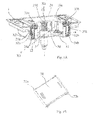
- the Figure 1A illustrates a sanitary system with an actuating device according to a first aspect of the present invention.
- the system comprises a support housing 1, and an actuating device, fixed, movably, on the support housing 1.
- the support housing 1 comprises a bottom wall 11 and four side walls 12, extending substantially to the right of the bottom wall 11.
- the actuating device comprises a plate 20 mounted on the support housing 1, substantially facing the bottom wall 11.
- the plate 20 is mounted to move on a central pusher 30, and the plate 20 is adapted to allow the user to operate one or the other of a large or a small flush of a flush mechanism.
- the plate 20 is provided for moving or tilting between a rest position, in which the plate 20 is substantially in the lid position of the support housing 1, and a first actuating position or a second actuating position, which actuates one of the big or small flush.
- the user can press, on the plate 20, one side or the other of the central pusher 30.
- At least one spring 5 is provided to urge the plate 20 towards its rest position.
- the spring 5 can be integrated with the central pusher 30, as illustrated in FIG. figure 1 . Otherwise, two or more springs may be provided to cooperate on either side of the middle section, such as with the ends of the plate 20 and return the plate 20 in the rest position.
- the central pusher 30 is substantially in the central position of the support housing 1.
- the central pusher 30 extends substantially perpendicular to the bottom wall of the support housing 1, and over the entire height of the side walls 12.
- the central pusher 30 and the bottom wall 11 form a marker, having a first axis X1, longitudinal, corresponding to a longitudinal axis of the central pusher, a second axis X2, transverse, located in the plane of the bottom wall 11 and passing by the central pusher 20, substantially orthogonal to the first axis X1, and a third axis X3, located in the plane of the bottom wall 11 and passing through the central pusher 30 substantially orthogonal to the first and second axes X1, X2.
- the first longitudinal axis X1 is substantially vertical
- the second transverse axis X2 is substantially oriented from left to right
- the third axis X3 is substantially oriented front to back.
- these guidelines are given by way of example only and can be modified according to the position of the housing.
- the plate 20 comprises a plate body 20a with a central bearing 21 and at least first and second opposed bearings 22a, 22b. More specifically, the central bearing 21 has a bearing surface 210 in contact with the central pusher 30.
- the first and second bearings 22a, 22b extend remotely, at two opposite ends of the plate body 20a, and have orientations. substantially parallel.
- first and second opposite bearings 22a, 22b are left and right bearings respectively extending respectively to the left and right ends of the plate 20.
- this orientation is given for illustrative purposes. only, and the bearings may also be front and rear bearings, for example, or any other respective orientation.
- First (left) and second (right) guide lights 32a, 32b are provided on at least one of the side walls 12, front and / or rear in the figures, to cooperate with the bearings 22a, 22b.
- the first and second guide lights 32a, 32b are designed to receive and guide respectively at least one of the ends 23a, 23b, front and / or rear in the figures, of the first (left) and second (right) bearings 22a, 22b.
- the first (left) and second (right) guide lights 32a, 32b each comprise a lateral guide portion or off-axis 33a, 33b, and a guide portion towards the bottom of the housing 34a, 34b, in the extension of the sections of misalignment guide 33a, 33b.
- the guide portions towards the bottom 34a, 34b are respectively on the outer ends of at least one of the side walls 12a, front and rear.
- the guide sections towards the bottom of the housing 34a, 34b are downward guide sections.
- the lateral guide section 33a, 33b is formed at the upper part of the side wall, front and / or rear.
- the lateral guide section 33a, 33b is substantially horizontal, in the operative position of the actuating device.
- the guide section to the bottom 34a, 34b is formed on the outer ends of the at least one side wall 12, front and / or rear.
- the bottom guide portion 34a, 34b is substantially vertical.
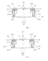
- FIG. 3 illustrates another actuator according to one aspect of the present invention
- the figure 4 illustrates yet another actuator according to another aspect of the invention.
- the actuating devices of the Figures 3 and 4 essentially differ from the actuating device as illustrated in the Figures 1A and 2A to 2C by the configuration of the guide lights.
- the actuating device illustrated in FIG. figure 3 comprises first (left) and second (right) guide lights 332a, 332b, on at least one of the side walls 12, front and / or rear, to cooperate with the bearings 22a, 22b.
- the first (left) and second (right) guide lights 332a, 332b each comprise a lateral guide section or off-axis 333a, 333b, and a guide portion to the bottom 334a, 334b, in the extension of the guide portions of misalignment 333a, 333b.
- the bottom guide portion 334a, 334b is substantially inclined towards the center of the side wall 12.
- the actuator illustrated in FIG. figure 4 comprises first (left) and second (right) guide lights 432a, 432b, on at least one of the side walls 12, front and / or rear, to cooperate with the bearings 22a, 22b.
- the first (left) and second (right) guide lights 432a, 432b each comprise a lateral guiding section or off-axis 433a, 433b, and a guide portion towards the bottom 434a, 434b, in the extension of the guiding sections of FIG. offsetting 433a, 433b.
- the bottom guide portion 434a, 434b is inclined towards the center of the side wall 12.
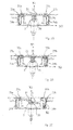
- the central bearing 21 of the plate 20 is substantially in the central position, on the central pusher 30, substantially aligned with the first axis X1.
- the user can press the plate 20, on one side or the other of the central pusher 30, according to the flushing mechanism that the user wishes to operate.
- Markings on the plate 20 can indicate which is the flush mechanism, small or large, activated associated with each side of the plate 20.
- the first (left) and second (right) bearings 22a, 22b slide in the respective lateral guide sections of the guide lights, moving on the side where the pressure is effected. , for example to the right as shown in the Figure 2B .
- the central bearing 21 also shifts to the right on the central pusher 30.
- the central bearing is no longer aligned with the first longitudinal axis X1.
- the second bearing 22b (right) is in abutment against the outer lateral end of the lateral guide section 33b in which the end 23b of the second bearing 22b (right) is inserted.
- the second bearing 22b tilts in the guide section towards the bottom 34b.
- the first bearing 22a continues to slide, to the right, in the lateral guide portion 33a, substantially horizontal, the guide light 32a with which it cooperates.
- the first bearing 22a also pivots on itself, to allow the translation to the bottom of the housing, the second bearing 22b (right).
- the second bearing 22b (right) is in abutment against the lower end of the guide portion towards the bottom 34b in which the end 23b of the second bearing 22b (right) is inserted.
- the second bearing 22b follows a first substantially horizontal translation movement, substantially parallel to the second transverse axis X2, to the right, followed by a second translation movement towards the bottom, substantially parallel to the first longitudinal axis X1.
- the translation towards the bottom is substantially vertical in the configuration of the guide lights of the figure 2 and in the operative position of the actuating device.
- the first bearing 22a (left) essentially follows a translation movement substantially horizontal, to the right, that is to say substantially parallel to the second transverse axis X2, and can also pivot on itself to allow the translation to the bottom the case of the second bearing 22b (left).
- the central bearing 21 follows a translation movement to the right, that is to say that the central bearing 21 is offset laterally with respect to the first longitudinal axis X1, thus losing the alignment with the first longitudinal axis X1 in laterally shifted relative thereto, followed by a translation movement towards the bottom of the housing associated with the second substantially vertical translation movement of the second bearing 22b.
- the first bearing 22a (left) undergoes a first substantially horizontal translation movement, to the left, substantially parallel to the second transverse axis X2, followed by a second translation movement substantially vertical, towards the bottom of the case.
- the second bearing 22b (right) essentially undergoes a substantially horizontal translation movement, to the left, substantially parallel to the second transverse axis X2.
- the central bearing 21 follows a translation movement to the left, that is to say substantially parallel to the second transverse axis X2, that is to say that the central bearing 21 is offset laterally relative to the first longitudinal axis X1 , followed by a translational movement towards the bottom of the housing, associated with the second substantially vertical translation movement of the first bearing 22a.
- first and second opposite bearings 22a, 22b which are left and right bearings, respectively, extending respectively to the left and right ends of the plate 20.
- the translation movement of the plate to the left or to the right in this orientation is a movement with a component along the second transverse axis X2.
- this orientation is given for illustrative purposes only, and the bearings can also be front and rear bearings, for example, the first translation movement of the plate then being a movement with a component along the third axis X3, or any other respective orientation.
- the horizontal and vertical orientations are given for illustrative purposes only, with reference to the illustrated figures. The respective orientations may vary with the positioning of the box.
- rocker plate is actually provided by translational movements, the bearings forming a cam.
- first and second bearings follow a simultaneous movement of translation during the rocker plate, substantially parallel to the second transverse axis X2.
- the plate body 20a including the central bearing and the first and second lateral bearings, is always in movement with respect to the casing 1 during the tilting of the plate between the rest position and the at least one position of actuation.
- the translational movements of the first and second bearings 22a, 22b are substantially horizontal and vertical translational movements.
- translation movements towards the bottom may not be substantially vertical but inclined relative to the vertical, as in the embodiments of the Figures 3 or 4 in which the guide lights towards the bottom are inclined relative to the vertical.
- the plate body 20a including the central bearing and the first and second lateral bearings, always moving relative to the housing 1 during the tilting of the plate between the rest position and the at least one actuating position.
- the guide lumens may be inclined relative to the horizontal and the vertical, substantially forming an inverted V, thereby resulting in rectilinear, upward and downward translational movements.
- the plate 20 undergoes a general movement towards the bottom only, without misalignment of the central bearing 21.
- the movement of the bearings 22a, 22b is blocked , the respective ends 23a, 23b abutting against the walls of the lateral guide sections 33a, 33b in which the ends 23a, 23b are inserted. As a result, the movement of the plate 20 is blocked.
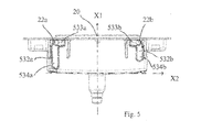
- the figure 5 illustrates another actuator according to yet another aspect of the present invention.
- the actuating device of the figure 5 essentially differs from the actuators illustrated on the Figures 1 to 4 by the configuration of the guide lights.
- the actuating device illustrated in FIG. figure 5 comprises first (left) and second (right) guide lights 532a, 532b, on at least one of the side walls 12, front and / or rear, to cooperate with the bearings 22a, 22b.
- the first (left) and second (right) guide lights 532a, 532b each comprise a lateral guiding section or off-axis 533a, 533b, and a guide portion towards the bottom 534a, 534b, in the extension of the guiding sections of FIG. off-centering 533a, 533b.
- the bottom guide portions 534a, 534b are of different lengths.
- the length of the guiding section towards the bottom makes it possible to adjust the travel of the plate 20.
- the illustrated case includes four side walls.
- other configurations are possible, for example a housing comprising two side walls provided with guide lights, for guiding the plate, and one or two open sides is also possible.
- the actuating device makes it possible to urge one side of the plate, with limited vertical displacement of the unsolicited end.
Landscapes
- Engineering & Computer Science (AREA)
- Public Health (AREA)
- Aviation & Aerospace Engineering (AREA)
- Health & Medical Sciences (AREA)
- Life Sciences & Earth Sciences (AREA)
- Hydrology & Water Resources (AREA)
- Mechanical Engineering (AREA)
- Water Supply & Treatment (AREA)
- Accommodation For Nursing Or Treatment Tables (AREA)
- Bidet-Like Cleaning Device And Other Flush Toilet Accessories (AREA)
- Feeding And Guiding Record Carriers (AREA)
- Toilet Supplies (AREA)
- Hydraulic Turbines (AREA)
Priority Applications (1)
| Application Number | Priority Date | Filing Date | Title |
|---|---|---|---|
| PL12183592T PL2568088T3 (pl) | 2011-09-09 | 2012-09-07 | Urządzenie uruchamiające płuczki ustępowej |
Applications Claiming Priority (1)
| Application Number | Priority Date | Filing Date | Title |
|---|---|---|---|
| FR1102748A FR2979928B1 (fr) | 2011-09-09 | 2011-09-09 | Dispositif d'actionnement de chasse d'eau |
Publications (3)
| Publication Number | Publication Date |
|---|---|
| EP2568088A2 true EP2568088A2 (de) | 2013-03-13 |
| EP2568088A3 EP2568088A3 (de) | 2013-08-07 |
| EP2568088B1 EP2568088B1 (de) | 2016-11-09 |
Family
ID=46758699
Family Applications (1)
| Application Number | Title | Priority Date | Filing Date |
|---|---|---|---|
| EP12183592.0A Active EP2568088B1 (de) | 2011-09-09 | 2012-09-07 | Auslösevorrichtung einer Wasserspülung |
Country Status (4)
| Country | Link |
|---|---|
| EP (1) | EP2568088B1 (de) |
| ES (1) | ES2606785T3 (de) |
| FR (1) | FR2979928B1 (de) |
| PL (1) | PL2568088T3 (de) |
Cited By (1)
| Publication number | Priority date | Publication date | Assignee | Title |
|---|---|---|---|---|
| FR3108924A1 (fr) * | 2020-04-06 | 2021-10-08 | Societe Clara | Dispositif de contrôle de chasse d’eau pour sanitaire à encombrement réduit |
Family Cites Families (3)
| Publication number | Priority date | Publication date | Assignee | Title |
|---|---|---|---|---|
| DE202006013850U1 (de) * | 2006-09-07 | 2008-01-10 | Viega Gmbh & Co. Kg | Betätigungsvorrichtung für einen Sanitärgegenstand, insbesondere für einen WC-Spülkasten |
| WO2009045442A1 (en) * | 2007-10-03 | 2009-04-09 | Fluidmaster, Inc. | Dual flush button assembly |
| PL2169126T3 (pl) * | 2008-09-29 | 2012-09-28 | Geberit Int Ag | Pneumatyczne urządzenie uruchamiające |
-
2011
- 2011-09-09 FR FR1102748A patent/FR2979928B1/fr active Active
-
2012
- 2012-09-07 EP EP12183592.0A patent/EP2568088B1/de active Active
- 2012-09-07 PL PL12183592T patent/PL2568088T3/pl unknown
- 2012-09-07 ES ES12183592.0T patent/ES2606785T3/es active Active
Non-Patent Citations (1)
| Title |
|---|
| None |
Cited By (2)
| Publication number | Priority date | Publication date | Assignee | Title |
|---|---|---|---|---|
| FR3108924A1 (fr) * | 2020-04-06 | 2021-10-08 | Societe Clara | Dispositif de contrôle de chasse d’eau pour sanitaire à encombrement réduit |
| WO2021205081A1 (fr) * | 2020-04-06 | 2021-10-14 | Societe Clara | Dispositif de controle de chasse d'eau |
Also Published As
| Publication number | Publication date |
|---|---|
| FR2979928A1 (fr) | 2013-03-15 |
| EP2568088B1 (de) | 2016-11-09 |
| FR2979928B1 (fr) | 2014-07-04 |
| EP2568088A3 (de) | 2013-08-07 |
| ES2606785T3 (es) | 2017-03-27 |
| PL2568088T3 (pl) | 2017-07-31 |
Similar Documents
| Publication | Publication Date | Title |
|---|---|---|
| WO2004010832A1 (fr) | Dispositif de prehension amovible et adaptable a differentes epaisseurs de recipient | |
| FR2947225A1 (fr) | Dispositif apte a fournir un support d'ecriture dans un vehicule automobile et planche de bord comportant un tel dispositif | |
| WO2011095931A1 (fr) | Véhicule à deux roues dépliable | |
| FR2776260A1 (fr) | Dispositif vide-vite pour embarcation et embarcation pneumatique qui en est equipee | |
| EP0922603B1 (de) | Vorratsbehälter für den Kraftstofftank eines Kraftfahrzeuges | |
| FR2817206A1 (fr) | Siege de vehicule dote d'un dossier rabattable vers l'avant | |
| EP2568088B1 (de) | Auslösevorrichtung einer Wasserspülung | |
| CH665379A5 (fr) | Necessaire de rasage. | |
| EP1938730B1 (de) | Saugrohr für Staubsauger | |
| EP0819875A1 (de) | Elektromagnetventil für Flüssigkeitsverteilung | |
| WO2017006039A1 (fr) | Poignee amovible munie d'un systeme d'ouverture a deux boutons pivotants | |
| EP1501694B1 (de) | Einziehbares ablagesystem für kabriolett mit faltdach | |
| EP0404609A1 (de) | Türschloss und -beschlag für Panikfälle | |
| FR2856267A1 (fr) | Suceur d'aspirateur | |
| FR2739116A1 (fr) | Reservoir de chasse a encastrer a commande par le dessus ou en facade | |
| EP1520504B1 (de) | Staubsaugerdüse | |
| EP0291433A1 (de) | Klappstuhl | |
| EP0967338B1 (de) | Spülkasten und sein Wasserzulauf | |
| EP4260783A1 (de) | Staubsaugermundstück mit nassreinigungsvorrichtung | |
| EP4260780A1 (de) | Staubsaugermundstück mit nassreinigungsvorrichtung | |
| EP1283316A1 (de) | Verbesserter Schlüssel mit gelenkigem Schlüsselbart | |
| FR3134301A1 (fr) | Suceur d’aspirateur équipé d’un dispositif de nettoyage humide | |
| FR2715553A1 (fr) | Suceur d'aspirateur à brosse escamotable commandée par au moins une pédale munie d'un bras d'appui. | |
| FR3155696A1 (fr) | Robot de nettoyage autonome équipé d’un dispositif de nettoyage | |
| FR3087160A1 (fr) | Systeme de montage d'un bol de trappe a carburant |
Legal Events
| Date | Code | Title | Description |
|---|---|---|---|
| PUAI | Public reference made under article 153(3) epc to a published international application that has entered the european phase |
Free format text: ORIGINAL CODE: 0009012 |
|
| AK | Designated contracting states |
Kind code of ref document: A2 Designated state(s): AL AT BE BG CH CY CZ DE DK EE ES FI FR GB GR HR HU IE IS IT LI LT LU LV MC MK MT NL NO PL PT RO RS SE SI SK SM TR |
|
| AX | Request for extension of the european patent |
Extension state: BA ME |
|
| PUAL | Search report despatched |
Free format text: ORIGINAL CODE: 0009013 |
|
| AK | Designated contracting states |
Kind code of ref document: A3 Designated state(s): AL AT BE BG CH CY CZ DE DK EE ES FI FR GB GR HR HU IE IS IT LI LT LU LV MC MK MT NL NO PL PT RO RS SE SI SK SM TR |
|
| AX | Request for extension of the european patent |
Extension state: BA ME |
|
| RIC1 | Information provided on ipc code assigned before grant |
Ipc: E03D 5/02 20060101AFI20130701BHEP |
|
| 17P | Request for examination filed |
Effective date: 20140207 |
|
| RBV | Designated contracting states (corrected) |
Designated state(s): AL AT BE BG CH CY CZ DE DK EE ES FI FR GB GR HR HU IE IS IT LI LT LU LV MC MK MT NL NO PL PT RO RS SE SI SK SM TR |
|
| 17Q | First examination report despatched |
Effective date: 20150417 |
|
| GRAP | Despatch of communication of intention to grant a patent |
Free format text: ORIGINAL CODE: EPIDOSNIGR1 |
|
| INTG | Intention to grant announced |
Effective date: 20160413 |
|
| GRAS | Grant fee paid |
Free format text: ORIGINAL CODE: EPIDOSNIGR3 |
|
| GRAA | (expected) grant |
Free format text: ORIGINAL CODE: 0009210 |
|
| AK | Designated contracting states |
Kind code of ref document: B1 Designated state(s): AL AT BE BG CH CY CZ DE DK EE ES FI FR GB GR HR HU IE IS IT LI LT LU LV MC MK MT NL NO PL PT RO RS SE SI SK SM TR |
|
| REG | Reference to a national code |
Ref country code: GB Ref legal event code: FG4D Free format text: NOT ENGLISH |
|
| REG | Reference to a national code |
Ref country code: AT Ref legal event code: REF Ref document number: 844059 Country of ref document: AT Kind code of ref document: T Effective date: 20161115 Ref country code: CH Ref legal event code: EP |
|
| REG | Reference to a national code |
Ref country code: IE Ref legal event code: FG4D Free format text: LANGUAGE OF EP DOCUMENT: FRENCH |
|
| REG | Reference to a national code |
Ref country code: DE Ref legal event code: R096 Ref document number: 602012025091 Country of ref document: DE |
|
| PG25 | Lapsed in a contracting state [announced via postgrant information from national office to epo] |
Ref country code: LV Free format text: LAPSE BECAUSE OF FAILURE TO SUBMIT A TRANSLATION OF THE DESCRIPTION OR TO PAY THE FEE WITHIN THE PRESCRIBED TIME-LIMIT Effective date: 20161109 |
|
| REG | Reference to a national code |
Ref country code: LT Ref legal event code: MG4D |
|
| REG | Reference to a national code |
Ref country code: NL Ref legal event code: MP Effective date: 20161109 |
|
| REG | Reference to a national code |
Ref country code: AT Ref legal event code: MK05 Ref document number: 844059 Country of ref document: AT Kind code of ref document: T Effective date: 20161109 |
|
| PG25 | Lapsed in a contracting state [announced via postgrant information from national office to epo] |
Ref country code: NO Free format text: LAPSE BECAUSE OF FAILURE TO SUBMIT A TRANSLATION OF THE DESCRIPTION OR TO PAY THE FEE WITHIN THE PRESCRIBED TIME-LIMIT Effective date: 20170209 Ref country code: LT Free format text: LAPSE BECAUSE OF FAILURE TO SUBMIT A TRANSLATION OF THE DESCRIPTION OR TO PAY THE FEE WITHIN THE PRESCRIBED TIME-LIMIT Effective date: 20161109 Ref country code: SE Free format text: LAPSE BECAUSE OF FAILURE TO SUBMIT A TRANSLATION OF THE DESCRIPTION OR TO PAY THE FEE WITHIN THE PRESCRIBED TIME-LIMIT Effective date: 20161109 Ref country code: GR Free format text: LAPSE BECAUSE OF FAILURE TO SUBMIT A TRANSLATION OF THE DESCRIPTION OR TO PAY THE FEE WITHIN THE PRESCRIBED TIME-LIMIT Effective date: 20170210 Ref country code: NL Free format text: LAPSE BECAUSE OF FAILURE TO SUBMIT A TRANSLATION OF THE DESCRIPTION OR TO PAY THE FEE WITHIN THE PRESCRIBED TIME-LIMIT Effective date: 20161109 |
|
| PG25 | Lapsed in a contracting state [announced via postgrant information from national office to epo] |
Ref country code: HR Free format text: LAPSE BECAUSE OF FAILURE TO SUBMIT A TRANSLATION OF THE DESCRIPTION OR TO PAY THE FEE WITHIN THE PRESCRIBED TIME-LIMIT Effective date: 20161109 Ref country code: FI Free format text: LAPSE BECAUSE OF FAILURE TO SUBMIT A TRANSLATION OF THE DESCRIPTION OR TO PAY THE FEE WITHIN THE PRESCRIBED TIME-LIMIT Effective date: 20161109 Ref country code: PT Free format text: LAPSE BECAUSE OF FAILURE TO SUBMIT A TRANSLATION OF THE DESCRIPTION OR TO PAY THE FEE WITHIN THE PRESCRIBED TIME-LIMIT Effective date: 20170309 Ref country code: RS Free format text: LAPSE BECAUSE OF FAILURE TO SUBMIT A TRANSLATION OF THE DESCRIPTION OR TO PAY THE FEE WITHIN THE PRESCRIBED TIME-LIMIT Effective date: 20161109 Ref country code: AT Free format text: LAPSE BECAUSE OF FAILURE TO SUBMIT A TRANSLATION OF THE DESCRIPTION OR TO PAY THE FEE WITHIN THE PRESCRIBED TIME-LIMIT Effective date: 20161109 Ref country code: IS Free format text: LAPSE BECAUSE OF FAILURE TO SUBMIT A TRANSLATION OF THE DESCRIPTION OR TO PAY THE FEE WITHIN THE PRESCRIBED TIME-LIMIT Effective date: 20170309 |
|
| PG25 | Lapsed in a contracting state [announced via postgrant information from national office to epo] |
Ref country code: SK Free format text: LAPSE BECAUSE OF FAILURE TO SUBMIT A TRANSLATION OF THE DESCRIPTION OR TO PAY THE FEE WITHIN THE PRESCRIBED TIME-LIMIT Effective date: 20161109 Ref country code: CZ Free format text: LAPSE BECAUSE OF FAILURE TO SUBMIT A TRANSLATION OF THE DESCRIPTION OR TO PAY THE FEE WITHIN THE PRESCRIBED TIME-LIMIT Effective date: 20161109 Ref country code: DK Free format text: LAPSE BECAUSE OF FAILURE TO SUBMIT A TRANSLATION OF THE DESCRIPTION OR TO PAY THE FEE WITHIN THE PRESCRIBED TIME-LIMIT Effective date: 20161109 Ref country code: RO Free format text: LAPSE BECAUSE OF FAILURE TO SUBMIT A TRANSLATION OF THE DESCRIPTION OR TO PAY THE FEE WITHIN THE PRESCRIBED TIME-LIMIT Effective date: 20161109 Ref country code: EE Free format text: LAPSE BECAUSE OF FAILURE TO SUBMIT A TRANSLATION OF THE DESCRIPTION OR TO PAY THE FEE WITHIN THE PRESCRIBED TIME-LIMIT Effective date: 20161109 |
|
| REG | Reference to a national code |
Ref country code: DE Ref legal event code: R097 Ref document number: 602012025091 Country of ref document: DE |
|
| PG25 | Lapsed in a contracting state [announced via postgrant information from national office to epo] |
Ref country code: IT Free format text: LAPSE BECAUSE OF FAILURE TO SUBMIT A TRANSLATION OF THE DESCRIPTION OR TO PAY THE FEE WITHIN THE PRESCRIBED TIME-LIMIT Effective date: 20161109 Ref country code: SM Free format text: LAPSE BECAUSE OF FAILURE TO SUBMIT A TRANSLATION OF THE DESCRIPTION OR TO PAY THE FEE WITHIN THE PRESCRIBED TIME-LIMIT Effective date: 20161109 Ref country code: BG Free format text: LAPSE BECAUSE OF FAILURE TO SUBMIT A TRANSLATION OF THE DESCRIPTION OR TO PAY THE FEE WITHIN THE PRESCRIBED TIME-LIMIT Effective date: 20170209 |
|
| PLBE | No opposition filed within time limit |
Free format text: ORIGINAL CODE: 0009261 |
|
| STAA | Information on the status of an ep patent application or granted ep patent |
Free format text: STATUS: NO OPPOSITION FILED WITHIN TIME LIMIT |
|
| REG | Reference to a national code |
Ref country code: FR Ref legal event code: PLFP Year of fee payment: 6 |
|
| 26N | No opposition filed |
Effective date: 20170810 |
|
| PG25 | Lapsed in a contracting state [announced via postgrant information from national office to epo] |
Ref country code: SI Free format text: LAPSE BECAUSE OF FAILURE TO SUBMIT A TRANSLATION OF THE DESCRIPTION OR TO PAY THE FEE WITHIN THE PRESCRIBED TIME-LIMIT Effective date: 20161109 |
|
| REG | Reference to a national code |
Ref country code: CH Ref legal event code: PL |
|
| PG25 | Lapsed in a contracting state [announced via postgrant information from national office to epo] |
Ref country code: MC Free format text: LAPSE BECAUSE OF FAILURE TO SUBMIT A TRANSLATION OF THE DESCRIPTION OR TO PAY THE FEE WITHIN THE PRESCRIBED TIME-LIMIT Effective date: 20161109 |
|
| REG | Reference to a national code |
Ref country code: IE Ref legal event code: MM4A |
|
| REG | Reference to a national code |
Ref country code: BE Ref legal event code: MM Effective date: 20170930 |
|
| PG25 | Lapsed in a contracting state [announced via postgrant information from national office to epo] |
Ref country code: LU Free format text: LAPSE BECAUSE OF NON-PAYMENT OF DUE FEES Effective date: 20170907 |
|
| PG25 | Lapsed in a contracting state [announced via postgrant information from national office to epo] |
Ref country code: CH Free format text: LAPSE BECAUSE OF NON-PAYMENT OF DUE FEES Effective date: 20170930 Ref country code: LI Free format text: LAPSE BECAUSE OF NON-PAYMENT OF DUE FEES Effective date: 20170930 Ref country code: IE Free format text: LAPSE BECAUSE OF NON-PAYMENT OF DUE FEES Effective date: 20170907 |
|
| PG25 | Lapsed in a contracting state [announced via postgrant information from national office to epo] |
Ref country code: BE Free format text: LAPSE BECAUSE OF NON-PAYMENT OF DUE FEES Effective date: 20170930 |
|
| REG | Reference to a national code |
Ref country code: FR Ref legal event code: PLFP Year of fee payment: 7 |
|
| PG25 | Lapsed in a contracting state [announced via postgrant information from national office to epo] |
Ref country code: MT Free format text: LAPSE BECAUSE OF FAILURE TO SUBMIT A TRANSLATION OF THE DESCRIPTION OR TO PAY THE FEE WITHIN THE PRESCRIBED TIME-LIMIT Effective date: 20161109 |
|
| PG25 | Lapsed in a contracting state [announced via postgrant information from national office to epo] |
Ref country code: HU Free format text: LAPSE BECAUSE OF FAILURE TO SUBMIT A TRANSLATION OF THE DESCRIPTION OR TO PAY THE FEE WITHIN THE PRESCRIBED TIME-LIMIT; INVALID AB INITIO Effective date: 20120907 |
|
| PG25 | Lapsed in a contracting state [announced via postgrant information from national office to epo] |
Ref country code: CY Free format text: LAPSE BECAUSE OF NON-PAYMENT OF DUE FEES Effective date: 20161109 |
|
| PGFP | Annual fee paid to national office [announced via postgrant information from national office to epo] |
Ref country code: TR Payment date: 20190904 Year of fee payment: 8 |
|
| PG25 | Lapsed in a contracting state [announced via postgrant information from national office to epo] |
Ref country code: MK Free format text: LAPSE BECAUSE OF FAILURE TO SUBMIT A TRANSLATION OF THE DESCRIPTION OR TO PAY THE FEE WITHIN THE PRESCRIBED TIME-LIMIT Effective date: 20161109 |
|
| PG25 | Lapsed in a contracting state [announced via postgrant information from national office to epo] |
Ref country code: AL Free format text: LAPSE BECAUSE OF FAILURE TO SUBMIT A TRANSLATION OF THE DESCRIPTION OR TO PAY THE FEE WITHIN THE PRESCRIBED TIME-LIMIT Effective date: 20161109 |
|
| REG | Reference to a national code |
Ref country code: DE Ref legal event code: R082 Ref document number: 602012025091 Country of ref document: DE Representative=s name: SONNENBERG HARRISON PARTNERSCHAFT MBB PATENT- , DE |
|
| PG25 | Lapsed in a contracting state [announced via postgrant information from national office to epo] |
Ref country code: TR Free format text: LAPSE BECAUSE OF NON-PAYMENT OF DUE FEES Effective date: 20200907 |
|
| P01 | Opt-out of the competence of the unified patent court (upc) registered |
Effective date: 20230512 |
|
| PGFP | Annual fee paid to national office [announced via postgrant information from national office to epo] |
Ref country code: PL Payment date: 20230829 Year of fee payment: 12 Ref country code: DE Payment date: 20230928 Year of fee payment: 12 |
|
| PGFP | Annual fee paid to national office [announced via postgrant information from national office to epo] |
Ref country code: ES Payment date: 20231019 Year of fee payment: 12 |
|
| REG | Reference to a national code |
Ref country code: DE Ref legal event code: R119 Ref document number: 602012025091 Country of ref document: DE |
|
| PG25 | Lapsed in a contracting state [announced via postgrant information from national office to epo] |
Ref country code: DE Free format text: LAPSE BECAUSE OF NON-PAYMENT OF DUE FEES Effective date: 20250401 |
|
| PGFP | Annual fee paid to national office [announced via postgrant information from national office to epo] |
Ref country code: GB Payment date: 20250929 Year of fee payment: 14 |
|
| PGFP | Annual fee paid to national office [announced via postgrant information from national office to epo] |
Ref country code: FR Payment date: 20250916 Year of fee payment: 14 |
|
| REG | Reference to a national code |
Ref country code: ES Ref legal event code: FD2A Effective date: 20251027 |
|
| PG25 | Lapsed in a contracting state [announced via postgrant information from national office to epo] |
Ref country code: ES Free format text: LAPSE BECAUSE OF NON-PAYMENT OF DUE FEES Effective date: 20240908 |
|
| PG25 | Lapsed in a contracting state [announced via postgrant information from national office to epo] |
Ref country code: PL Free format text: LAPSE BECAUSE OF NON-PAYMENT OF DUE FEES Effective date: 20240907 |