EP2569033B1 - Aerosolgeneratoranordnung - Google Patents
Aerosolgeneratoranordnung Download PDFInfo
- Publication number
- EP2569033B1 EP2569033B1 EP11718125.5A EP11718125A EP2569033B1 EP 2569033 B1 EP2569033 B1 EP 2569033B1 EP 11718125 A EP11718125 A EP 11718125A EP 2569033 B1 EP2569033 B1 EP 2569033B1
- Authority
- EP
- European Patent Office
- Prior art keywords
- vibratable
- piezo ceramic
- electrical contact
- ceramic body
- cup
- Prior art date
- Legal status (The legal status is an assumption and is not a legal conclusion. Google has not performed a legal analysis and makes no representation as to the accuracy of the status listed.)
- Active
Links
Images


Classifications
-
- B—PERFORMING OPERATIONS; TRANSPORTING
- B05—SPRAYING OR ATOMISING IN GENERAL; APPLYING FLUENT MATERIALS TO SURFACES, IN GENERAL
- B05B—SPRAYING APPARATUS; ATOMISING APPARATUS; NOZZLES
- B05B17/00—Apparatus for spraying or atomising liquids or other fluent materials, not covered by the preceding groups
- B05B17/04—Apparatus for spraying or atomising liquids or other fluent materials, not covered by the preceding groups operating with special methods
- B05B17/06—Apparatus for spraying or atomising liquids or other fluent materials, not covered by the preceding groups operating with special methods using ultrasonic or other kinds of vibrations
- B05B17/0607—Apparatus for spraying or atomising liquids or other fluent materials, not covered by the preceding groups operating with special methods using ultrasonic or other kinds of vibrations generated by electrical means, e.g. piezoelectric transducers
- B05B17/0653—Details
- B05B17/0676—Feeding means
-
- A—HUMAN NECESSITIES
- A61—MEDICAL OR VETERINARY SCIENCE; HYGIENE
- A61M—DEVICES FOR INTRODUCING MEDIA INTO, OR ONTO, THE BODY; DEVICES FOR TRANSDUCING BODY MEDIA OR FOR TAKING MEDIA FROM THE BODY; DEVICES FOR PRODUCING OR ENDING SLEEP OR STUPOR
- A61M11/00—Sprayers or atomisers specially adapted for therapeutic purposes
- A61M11/005—Sprayers or atomisers specially adapted for therapeutic purposes using ultrasonics
-
- A—HUMAN NECESSITIES
- A61—MEDICAL OR VETERINARY SCIENCE; HYGIENE
- A61M—DEVICES FOR INTRODUCING MEDIA INTO, OR ONTO, THE BODY; DEVICES FOR TRANSDUCING BODY MEDIA OR FOR TAKING MEDIA FROM THE BODY; DEVICES FOR PRODUCING OR ENDING SLEEP OR STUPOR
- A61M15/00—Inhalators
- A61M15/0085—Inhalators using ultrasonics
-
- A—HUMAN NECESSITIES
- A61—MEDICAL OR VETERINARY SCIENCE; HYGIENE
- A61M—DEVICES FOR INTRODUCING MEDIA INTO, OR ONTO, THE BODY; DEVICES FOR TRANSDUCING BODY MEDIA OR FOR TAKING MEDIA FROM THE BODY; DEVICES FOR PRODUCING OR ENDING SLEEP OR STUPOR
- A61M15/00—Inhalators
- A61M15/02—Inhalators with activated or ionised fluids, e.g. electrohydrodynamic [EHD] or electrostatic devices; Ozone-inhalators with radioactive tagged particles
- A61M15/025—Bubble jet droplet ejection devices
-
- A—HUMAN NECESSITIES
- A61—MEDICAL OR VETERINARY SCIENCE; HYGIENE
- A61M—DEVICES FOR INTRODUCING MEDIA INTO, OR ONTO, THE BODY; DEVICES FOR TRANSDUCING BODY MEDIA OR FOR TAKING MEDIA FROM THE BODY; DEVICES FOR PRODUCING OR ENDING SLEEP OR STUPOR
- A61M2202/00—Special media to be introduced, removed or treated
- A61M2202/04—Liquids
- A61M2202/0468—Liquids non-physiological
-
- B—PERFORMING OPERATIONS; TRANSPORTING
- B05—SPRAYING OR ATOMISING IN GENERAL; APPLYING FLUENT MATERIALS TO SURFACES, IN GENERAL
- B05B—SPRAYING APPARATUS; ATOMISING APPARATUS; NOZZLES
- B05B17/00—Apparatus for spraying or atomising liquids or other fluent materials, not covered by the preceding groups
- B05B17/04—Apparatus for spraying or atomising liquids or other fluent materials, not covered by the preceding groups operating with special methods
- B05B17/06—Apparatus for spraying or atomising liquids or other fluent materials, not covered by the preceding groups operating with special methods using ultrasonic or other kinds of vibrations
- B05B17/0607—Apparatus for spraying or atomising liquids or other fluent materials, not covered by the preceding groups operating with special methods using ultrasonic or other kinds of vibrations generated by electrical means, e.g. piezoelectric transducers
- B05B17/0638—Apparatus for spraying or atomising liquids or other fluent materials, not covered by the preceding groups operating with special methods using ultrasonic or other kinds of vibrations generated by electrical means, e.g. piezoelectric transducers spray being produced by discharging the liquid or other fluent material through a plate comprising a plurality of orifices
- B05B17/0646—Vibrating plates, i.e. plates being directly subjected to the vibrations, e.g. having a piezoelectric transducer attached thereto
Definitions
- the invention relates to aerosol generators and in particular to liquid aerosol droplet generators which are often electronically controlled for example those of the piezo-based type. More particularly, the invention relates to improvements to electronic piezo-based liquid aerosol generator assemblies.
- Existing electronic piezo based aerosol generator devices typically comprise an actuator unit which generally utilises a support substrate (generally a disc-shaped metal, such as stainless steel or a brazing metal or alloy) having a central orifice adapted to accommodate a nozzle plate, which typically has a dome shaped central portion surrounded by an edge which is suitable for mounting the plate onto the support substrate.
- the nozzle plate is provided with a plurality of orifices of about 3 - 5 microns in diameter.
- a ring of actuatable material typically a piezoelectric (“piezo") ceramic material, is mounted onto the support substrate about the central orifice.
- the nozzle plate is in the form of a vibratable member and typically comprises a thin flexible membrane material surrounded by a mounting flange or edge.
- International Publication No. WO 2009/042187 describes a typical example of such a device.
- Radial oscillations or vibrations generated within the piezo ceramic material are transferred through the support substrate to the flexible membrane and induce vertical vibration/flexing of the nozzle plate. It is the vertical vibrating and/or flexing action of the membrane of the nozzle plate which aerosolizes a liquid by driving the liquid through the apertures in the nozzle plate by way of the vertical flexing action.
- a dome shaped nozzle plate amplifies the effect of the vibration.
- the vertical vibration/flexing of the nozzle plate membrane produces a micropumping action at the surface of nozzle plate in contact with liquid to force liquid through the plurality of orifices in the nozzle plate membrane, thereby generating an aerosolized fluid, which typically takes the form of, for example, liquid droplets, such as those of a dissolved drug, suspended in air.
- the support substrate In addition to holding the piezo ceramic disc and the nozzle plate, the support substrate amplifies and transmits the oscillations/vibrations generated in the piezo ceramic to the flexible membrane nozzle plate.
- the orifices in the nozzle plate may be funnel shaped to maximise pumping efficiency and aerosol formation.
- the support also acts as a base structure to isolate the piezo ceramic body from the liquid path by providing a foundation for sealant materials such as epoxy and silicone, which are typically used to isolate the piezo ceramic body from liquid and aerosol.
- sealant materials such as epoxy and silicone
- Prior art piezo ceramic materials suitable for actuators typically comprise a piezo ceramic material which is coated with a layer of electrical contact material, typically in the form of a (thin) layer or film of a conductive material which is deposited or coated on top of the ceramic surface, in the form of a metallized electrode.
- a layer of electrical contact material typically in the form of a (thin) layer or film of a conductive material which is deposited or coated on top of the ceramic surface, in the form of a metallized electrode.
- a film of silver electrode can be coated on the surface area of at least one face of the piezo surface.
- this film of electrical contact material is provided on at least one of the entire opposing surfaces of the piezo carried out during manufacture, for example, by a screen printing or sputtering process.
- the film of conductive material making up the electrical contact material is generally in the order of 3 to 10 micron thickness. It typically covers at least one entire side of the piezo material.
- the film is needed to facilitate passage of current across/through the piezo material over all or a large proportion of its surface area to cause it to vibrate.
- the film conductive material making up the electrical contact material functions as an electrode to assist in power transfer through the body of the piezo ceramic material.
- a number of prior art devices utilise distinct regions or areas of screen printed conductive material making up the electrical contact material electrodes on the ceramic body to form a drive electrode and a sense electrode which monitors and ensures resonant vibration of the body is maintained.
- the support substrate (typically a metal support ring) may act as an electrode for the (opposite face of the) piezo ceramic body, thereby providing a completed circuit which facilitates application of an electrical signal to be applied across the piezo for inducing vibration thereof.
- the piezo will be bonded to the support substrate in a manner that does not hinder electrical conduction, for example, brazing or through use of a conducting adhesive.
- the metal supporting substrate is to act as an electrode, it is necessary to have the supporting substrate conductively attached (for example, bonded by a conductive epoxy material) to the piezo to ensure current can flow from the electrode through the piezo.
- the entire actuator can then be coated with sealant materials to resist moisture ingress. Such sealants can however result in undesirable dampening of vibration or may lead to inconsistent actuation from device to device.
- piezo ceramic actuators Three factors affecting the lifetime of piezo ceramic actuators are humidity, operating voltage and temperature.
- the piezo ceramic materials used in piezo ceramic actuator are moisture sensitive. Ingressing moisture and the electric field applied can cause electrochemical transport processes in the piezo ceramic actuator, which are accelerated by higher temperatures. While it is straightforward to develop a waterproof piezo ceramic actuator utilising waterproof coatings, making them vapour tight is more difficult.
- the piezo ceramic actuator When exposed to moisture over time, the piezo ceramic actuator frequently short circuits. For example a short circuit can occur between the electrodes or screen printed surface films of conducting material, which can cause irreparable damage to the piezo ceramic actuator and leads to premature device failure.
- prior art piezo ceramic actuator devices are often coated in a sealant material (for example, an epoxy coating) that is cured to protect the piezo ceramic actuator circuit from moisture.
- a sealant material for example, an epoxy coating
- the entire circuit may then be encased in a protective silicon layer to increase insulation.
- water vapour can still penetrate these polymers and so the piezo ceramic actuator generally needs to be sealed from moisture ingress. Sealing increases the manufacturing costs of the piezo ceramic actuator unit.
- the attachment area where the nozzle plate is attached to the supporting substrate is particularly susceptible to corrosion and thus leaking, making the device more prone to shorting.
- flow rate is controlled by voltage applied across the piezo ceramic body.
- the maximum operating voltage may be limited by the piezo ceramic actuators dimensions.
- the optimum operating voltage must be selected carefully to achieve optimum performance requirements as too high a voltage may damage the device. Devices therefore that give higher flow rates using lower operating voltages are desirable as the lifetime of the device will be extended when compared to piezo ceramic actuators requiring higher operating voltages to achieve the same flow rate. Therefore, dampening should be avoided as far as possible.
- United States Patent No. 5,823,428 and International Publication No. WO 93/10910 each describes an apparatus for atomizing a liquid in which the liquid is passed through tapered perforations in a vibrating membrane.
- the perforate vibrating member and a piezoelectrical annulus are bonded onto an apertured support substrate which is an annulus of a nickel iron alloy.
- the perforate vibrating member is bonded across the aperture of the support substrate, not directly bonded across the aperture of the piezoelectrical annulus.
- Use of such an apertured support substrate is typical of prior art atomiser or aerosol generators assemblies which require multi manufacturing steps to attach the piezo to the support substrate and seal the arrangement to render it impermeable to liquids.
- Figure 4 shows a plan view of the unit where two metallisation electrodes can be found, the first being a drive electrode and the second an optional sense electrode.
- the specification discloses that these electrodes are electrically insulated through a 0.5 mm air gap between the electrode regions. The electrodes operate together to maintain resonant vibration of the actuator.
- United States Publication No. US 2008/0308096 describes an aerosol generating device which includes a membrane for atomizing a liquid; an actuating device comprising a flexible substrate plate onto which a piezo actuating device is mounted. A membrane for aerosol generation is mounted onto the piezo actuating device within an aperture provided therein.
- the preferred flexible substrate plate material is described as flexible printed circuit boards or conductor boards onto which electrical conductors made of Cu, Ag, Al etc. are applied or boards in which such conductors are already integrated. The electrical conductors supply power to the piezo actuating device. It also describes how the actuating device is bonded or soldered onto the membrane and flexible substrate.
- the membrane has collar of variable width so that the actuating device can be completed or partially covered by the collar.
- it is taught to bond the membrane and the actuating device to a metal substrate which ensures occurrence of flexural oscillations.
- the device comprises a flexural plate onto which a plurality of actuator means are bonded such that the confluence of waves generated by vibration induced in the plate coincides with a linear array of nozzles.
- the actuator means are said to be electroded by screen printed silver to within 0.5mm of the top and bottom edges of the piezoelectric to enable electrical connection.
- United States Publication No. US 2006/0207591 describes an aerosol generating assembly for inhalation therapy devices, in which an oscillatable assembly, consisting of a membrane, a piezo electric oscillation generator and a substrate to which the membrane is attached, is mounted in an encapsulating means such that at least the membrane is exposed for the supply of liquid and the generation of an aerosol, whereas the remaining parts of the oscillatable assembly are protected. Mounting occurs by means of a flexible passage which touches the assembly in the region of an oscillation nodal line, such that the oscillatory motions of the oscillatable assembly are not negatively affected. However, it is likely that the flexible nature of the passage may lead to problems arising from moisture ingress on vibration.
- the structural arrangement of the aerosol generator assembly of the invention is less prone to defects from corrosion and less prone to dampening of the actuation of the piezo ceramic actuator, since a substrate support is not required.
- the contact material free-zone decreases the risk of moisture induced shorting as described below and forms a convenient area for assembling the actuator into an inhalation device (described below).
- the layer of electrical contact material may comprise a film of conductive material coated onto the surface of the vibratable piezo ceramic body.
- the electrical contact free zone is provided on the vibratable piezo ceramic body about the aperture therein to provide, on the same side of the body, a surface region which is coated with the film of conductive material and a surface region which is not coated with the film of conductive material and onto which the vibratable member may be mounted.
- the vibratable member engages the vibratable piezo ceramic body on top of the electrical contact material free-zone (within the electrical contact free zone) provide about the aperture therein, to thereby cover the aperture on one side of the body.
- the vibratable member comprises a rimmed edge which is mounted onto the vibratable body within the electrical contact material free-zone to form the gap area.
- the arrangement means that the vibratable member does not extend out of the contact material free-zone.
- the contact material free-zone is typically of width 1 to 3 mm of exposed ceramic material from the edge of the aperture.
- the vibratable member and the contact material are laterally spaced apart.
- the arrangement is such that there is a space or a gap or border between the terminating edge of the contact material and a periphery (for example a rim edge) of the vibratable member.
- the gap area is formed about the aperture defined in the vibratable body at the edge of the aperture and about its perimeter. The gap area is completely free of contact material such that the (naked) piezo ceramic material is exposed in this area.
- the vibratable member does not occupy the entire contact material free-zone and that there remains a border of the contact material free-zone about the vibratable member that the vibratable member does not occupy.
- This border area is typically of width 1 to 2 mm of exposed ceramic material. The gap or border area is important as, when the vibratable member is positioned over the aperture and its edges rest on the vibratable piezo ceramic body within the electrode free zone, it electrically insulates the terminating edge of the electrode contact material from the vibratable member.
- the vibratable member may be mounted onto the vibratable body electrode free-zone at this edge or flange.
- the vibratable member and the contact material are never in any superimposed arrangement, where one overlies the other. Instead, it is preferred that vibratable member only overlies the vibratable body in the contact material free-zone, as the gap or border area free of the film of electrode contact material is necessary to reduce circuit shorting.
- a sealing material occupies said border thus further preventing liquid from transferring from the vibratable member to the contact material.
- such sealing takes place during incorporation of the assembly into an inhalation device.
- the combination of gap and gap sealing means there is a much reduced risk of shorting due to liquid reaching the contact material/piezo.
- one of the major issues with prior art devices is that over time moisture ingress of liquid material (and/or atomised material) from the vibratable membrane can make its way into contact with the electrical contact material and cause a short circuit across the vibratable body ending the useful life of the device. This happens frequently in prior art devices despite attempts to create a sufficiently good seal to prevent fluid ingress.
- the arrangement of the present invention is of great importance as it allows a hermetic seal to be formed on the vibratable body about the vibratable member and within the contact material free-zone, such that there is a seal disposed about the vibratable body within the gap formed between the electrical contact material and the vibratable member. This means that if there is aerosol fluid or vapour ingress along the vibratable member, the fluid will be prevented from coming into the direct contact with the electrical contact material required for shorting to occur.
- the aerosol generator assembly of the invention is thus much less likely to fail due to creation of a short circuit between regions of the electrical contact material on opposing sides of the piezo ceramic body.
- a complete short circuit will occur when moisture bridges between the electrical contact material layers, for example on opposing sides of the vibratable body.
- Device failure due to such shorting can occur in prior art devices after a relatively brief period of use, disabling the device.
- the assembly of the invention is advantageous since with the electrical contact free zone and gap provided therein, the vibratable membrane does not sit directly over the electrical contact material. Any aerosol that may ingress does not create a short circuit path which would otherwise be completed from the top electrode through the vibratable membrane through aerosol produced and onto the bottom electrode to short circuit the device.
- the sealing arrangement of the present invention is advantageous over existing polymer sealing methods as fewer production steps are required (no metal substrate is required), significantly less sealant materials are required and therefore production costs are reduced.
- the vibratable body is constructed from a piezo ceramic-based material to form an actuatable piezo ceramic body.
- the vibratable body is annular or substantially disc shaped.
- the piezo ceramic-based material is one with piezo electrical properties.
- the vibratable body is made of a piezo electric material such as lead zirconate titanite (PZT) or the like.
- PZT lead zirconate titanite
- a layer of electrical contact material, in form of a film of conducting material is provided on each of the opposing sides/faces of the vibratable body, typically by a screen printing, metallization or a sputter coating technique.
- the vibratable member is adapted to repetitively move up and down in the vertical direction upon vibration imparted to it by the vibratable body. This oscillation motion causes a micropumping action so as to atomise a fluid by drawing fluid into the pores and ejecting it in an atomised state. Since the need for a substrate and large amounts of sealant materials are eliminated, dampening problems are avoided.
- the vibratable member may take the form of an annular thin sheet of any suitable material whose properties provide a corrosive resistant, robust, yet flexible structure, for example, a metal or metal alloy or a suitable polymeric material.
- the sheet has a thickness of between 10 and 100 microns, but more preferably between 30 and 60 microns.
- the vibratable member is desirably bonded into place on the vibratable body within the electrode free zone, on top of naked piezo ceramic material about the aperture provided therein.
- the vibratable member is non planar in shape to assist in aerosol formation.
- the vibratable member is curved for example dome-shaped to ensure improved aerosol formation.
- the dome and aperture in the vibratable body are dimensioned so that, when mounted, the dome portion of the vibratable member may sit within the aperture occupying the area formed therein.
- the apertures in the vibratable member may be tapered and reducing in cross-sectional area from a first side which is in contact with liquid to be atomised to a second side which ejects the atomised liquid.
- This aperture geometry is typical of a current electroformed nozzle plate manufacturing process. Funnel shaped pores assist in aerosol particle formation.
- the vibratable member may be mounted onto the vibratable body by a retaining collar or flange area, which allows the member to flex while providing a mounting means to mount the vibratable member to the vibratable body.
- the annular disc may be provided with rimmed edge surrounding the dome. This is useful for providing an area so that the disc may be mounted on top of the vibratable body such that the dome shape is centred upon and desirably within the aperture of the vibratable body.
- the film of electrical contact material is for applying an electrical signal across the vibratable body in order to induce oscillation/vibration within it.
- the layer or film of electrical contact material is coated on the vibratable body when the body is manufactured.
- the contact material free-zone is provided on both sides of the body. This means an appropriate seal can be provided on opposing sides of the vibratable body, if required.
- the assembly of the invention further comprises a complementary delivery cup and/or an ejection cup for enhancing the seal and operability of the assembly as described below.
- a delivery cup for example a medication cup, having a mouth that is dimensioned to mate with the vibratable piezo ceramic body about the aperture and mounted on the vibratable piezo ceramic body by attaching the mouth thereof to the vibratable body, the delivery cup forming a reservoir for liquid to be aerosolized by the vibratable member characterised in that the vibratable body comprises a gap or a border of the electrical contact material free-zone about the vibratable member that the vibratable member does not occupy and onto which the mouth of the delivery cup is mounted.
- an aerosol generator assembly comprising:
- the vibratable body is a vibratable piezo ceramic body.
- An electrical contact material free-zone is provided on at least one side of the body about the aperture.
- the electrical contact material free zone and the vibratable member are dimensioned so that the vibratable member is mounted directly onto the vibratable body on top of the electrical contact material free-zone such that a gap area free of electrode contact material is formed between the terminating edge of the electrical contact material and the periphery of the vibratable member.
- the mouth of the delivery cup mates with the vibratable piezo ceramic body about the aperture defined therein, and is mounted on the vibratable body by attaching the mouth thereof to the vibratable body within the electrode contact free, the delivery cup forming a reservoir for liquid to be atomised by the vibratable member.
- the mouth of the delivery cup mates with the vibratable body over the electrode contact free zone, such that the gap or border around the aperture is seal or closed off by the mouth of the delivery cup.
- Sealant may be provided about the electrode contact free zone, the gap or border formed between the mounting edge of the vibratable member and the terminating edge of the film of electrical contact material, the mate or connection area.
- the delivery cup is mounted on the vibratable body with a seal provided between the lower mouth of the delivery cup and the vibratable body.
- a bonding material used to bond the delivery cup to the vibratable body forms an appropriate seal, as well as an electrical insulator.
- the vibratable member is sandwiched between the mouth of the delivery cup and the vibratable body (piezo). This again is an important arrangement as no liquid can pass outside of the boundary of the mouth of the delivery cup.
- the delivery cup has a (decreasing) tapered profile towards its lower mouth.
- a second end (or upper mouth) of the delivery cup may be provided with a closure for retaining liquid to be aerosolized within the delivery cup.
- the delivery cup can thus act as a funnel for delivery of liquid to the vibratable member.
- a layer of electrical contact material is provided on the vibratable body; however, an electrical contact free zone is provided about the aperture.
- the aperture has a circular shape and the electrical contact free zone is provided as an annular zone about the aperture.
- the mouth of the delivery cup is dimensioned to mate with the vibratable body about the aperture and within the electrical contact free zone.
- the mouth of the delivery cup is dimensioned so that it is smaller than the dimensions of the electrical contact free zone.
- That gap or border may be provided with a seal for example formed by a sealant material.
- the arrangement advantageously isolates the moisture area associated with from the contact areas, thus reducing opportunity for moisture ingress from the region about the flexible nozzle plate membrane and associated piezo short-circuiting.
- the delivery cup is calibrated or graduated so that quantities of liquid therein may be easily determined.
- the delivery cup may be adapted or connected to a liquid supply source to assist in continuous generation of aerosolised material.
- the aerosol generating assembly of the invention is also provided with an ejection cup, having a mouth that is dimensioned to mate with the vibratable piezo ceramic body about the aperture and mounted on the vibratable piezo ceramic body by attaching the mouth thereof to the vibratable body, the ejection cup forming an ejection guide for ejected liquid aerosolized by the vibratable member.
- An aerosol generator assembly of the invention may further comprise:
- the mouth of the ejection cup may mate with the vibratable body over the electrode contact free zone, such that the gap or border around the aperture is sealed or closed off by the mouth of the delivery cup.
- Sealant may be provided about the electrode contact free zone, the gap or border formed between the mounting edge of the vibratable member and the terminating edge of the film of electrical contact material, the mate or connection area.
- the ejection cup is mounted on the vibratable body with a seal provided between the mouth of the ejection cup and the vibratable body.
- a seal provided between the mouth of the ejection cup and the vibratable body.
- a bonding material used to bond the ejection cup to the vibratable body forms an appropriate seal.
- the vibratable member and vibratable body are sandwiched in position between the mouth of the delivery cup and the mouth of the ejection cup.
- the contact free zone about the mouth of the housing may be sealed with a moisture blocking sealant such as an epoxy.
- the delivery cup and the ejection cup will be on opposing sides of the vibratable body to form an atomiser assembly.
- the assembly defines a channel or a passageway in the central portion of the device in which fluid is provided to the rear of the vibratable member and provided as an aerosol on the other side of the vibratable member.
- the assembly ensures that the vibratable body and the electrical contact material provided thereon, is sealed from the central passageway portion of the device where fluid/liquid is atomised.
- the ejection cup has an (increasing) tapered profile away from its mouth.
- a second end of the ejection cup may be provided with a closure for when the device is not in use.
- the ejection cup can thus act as a discharge funnel for discharge of ejected atomised fluid.
- the ejection cup may be provided with a connector or mating adapter to allow the cup to be attached to a delivery means, for example, an inhalation mask or the like.
- an aerosol generator assembly comprising:
- a layer of electrical contact material is provided on the vibratable body but that an electrical contact free zone (as described above) is provided about the aperture on at least one face (surface) of the vibratable body.
- the aperture has a circular shape and the electrical contact free zone is an annular zone about the aperture on the upper face of the vibratable body in contact with the medication cup.
- the mouth of the ejection cup is dimensioned to mate with the vibratable body about the aperture and within the electrical contact free zone (to overlie the electrical contact free zone, gap formed therein and the edge or flange of the mounted vibratable member).
- the mouth of the ejection cup is dimensioned so that it is smaller than the dimensions of the electrical contact free zone. This means that mating of the ejection cup to the vibratable body leaves a gap between the contact material and the ejection cup. That gap may be provided with a seal for example formed by a sealant material.
- both delivery and ejection cups for controlling the path of the fluid to be aerosolized and the path of the aerosolized fluid.
- the vibratable body is the structural element to which both the delivery and ejection cups are attached.
- the assembly defines a channel or a passageway in the central portion of the device in which fluid is provided to the rear of the vibratable member and provided as an aerosol on the other side of the vibratable member.
- the delivery cup and/or ejection cup are combined with the aspect of having an electrical contact material free-zone about the aperture on one or both sides of the vibratable body. This ensures that the vibratable body and the electrical contact material provided thereon, is sealed from the central passageway portion of the device where fluid/liquid is aerosolized.
- the vibratable body may be provided with electrical connectors, such as electrical leads for supply of a suitable electrical signal to the electrical contacts of the vibratable body.
- the assembly may be adapted to facilitate connection to a power source.
- the electrical connections may also be protected within such an arrangement.
- a housing may be provided for housing the vibratable body and the vibratable member and, optionally further, one or both of the delivery cup and the ejection cup.
- the ejection cup is integrally formed with a housing which also houses a delivery cup and the vibratable body and the vibratable member.
- the housing further comprises a guide conduit through which electrical wires can be passed to provide an electrical signal to the vibratable body.
- FIG 1A shows the individual components of a piezo ceramic actuator A according to the present invention, as illustrated generally by reference sign A.
- the piezo ceramic actuator A comprises a flexible nozzle/membrane plate 1 and an annular piezo ceramic body 2 (vibratable piezo ceramic body) having a centrally disposed aperture O disposed therein.
- the annular piezo ceramic body 2 is surface coated with a film of electrical contact material 3, except in the region about the centrally disposed aperture O which is not coated with electrical contact material 3.
- the flexible nozzle/membrane plate 1 is dome shaped (as shown in Figures 3A & 3B ) and comprises a retaining collar or flange 5 to facilitate mounting nozzle/membrane plate 1 onto the annular piezo ceramic body 2 such that the dome of the nozzle/membrane plate 1 resides within aperture O of the annular piezo ceramic body 2 (see down arrow of Figure 1A ) and such that the retaining collar or flange 5 sits on top of the vibratable body within the electrical contact free zone 4.
- the mounting arrangement is in such a manner that an insulating border or gap G of naked (exposed) piezo ceramic material is formed between the edge of the retaining collar 5 of the mounting nozzle/membrane plate 1 and the terminating edge of the film of the electrical contact material 3 present on the surface of the piezo ceramic vibratable body about the aperture provided therein (see Figure 1B for the assembled piezo ceramic actuator A assembly).
- the border or gap G is therefore formed as an annular ring of the naked surface of the annular piezo ceramic body 2, which is not coated with the film of electrical contact material 3.
- FIG. 2 illustrates the component parts of an aerosol generator assembly N of the present invention.
- the component parts of the aerosol generator assembly N of Figure 1B are shown.
- the annular piezo ceramic body 2 (vibratable piezo ceramic body) of piezo ceramic actuator A is provided with a pair of electrical contact connectors 6 for supplying electricity to the film of electrical contact material coated onto the surface of the piezo ceramic body 2 (vibratable piezo ceramic body).
- the electrical contact connectors 6 contact a portion of the film of electrical contact material 3 on each of the opposite sides of the annular piezo ceramic body 2, thus completing a circuit and allowing current to pass through the piezo ceramic body to induce vibration.
- FIG. 2 shows aerosol generator housing H, which is assembled around piezo ceramic actuator A in the assembled device.
- the lower part of housing H is provided with a protecting sleeve 7 for accommodating and protecting electrical contact connectors 6.
- a plug adapter 8 is also shown and is adapted to be insertable into protecting sleeve 7.
- the plug adapter 8 mates with the terminals of electrical contact connectors 6 to form a plug type arrangement, which allows an electrical power cable (not shown) to be removeably plugged into the plug adapter 8, when the device is ready for use.
- the aerosol generator assembly N also comprises a medication cup M which serves as a reservoir and funnel for medication to be aerosolized.
- the medication cup M comprises walls 9 which taper inward towards the bottom of the cup to form a funnel shaped mouth.
- the medication cup M is dimensioned to be snugly accommodated into the mouth 11 of the housing H to seal off the piezo ceramic actuator A from outside and to complete the aerosol generator assembly N.
- the medication cup M is provided with a further rim 12 about the head of the medication cup to facilitate addition of a cap 13 (shown in Figure 3A and 3B ).
- the housing H is provided with a tabbed spine T which runs part way down the housing to assist inserting the device into an inhalation mask in the correct orientation.
- FIG 3A shows a diagonal section through the assembled aerosol generator assembly N of the invention and Figure 3B shows a section through line L-L as shown in Figure 3A .
- the ejection cup E forms the lower part of the housing H.
- the ejection cup E is shaped as an inverted funnel to assist in delivering generated aerosol.
- walls 14 of ejection cup E taper inwards towards the top of the ejection cup E.
- the upper surface of the tapered ejection cup walls 14 form a flat rim 15 dimensioned such that the piezo ceramic actuator A sits on top of and is supported by the flat rim 15 of the ejection cup E.
- the walls 9 of the medication cup M tapered inwards towards the bottom of the medication cup M to form a rim 10 and are dimensioned to match that of the rim 15 of the ejection cup E.
- rim 10 of the medication cup M rests over the piezo ceramic actuator A in exactly the opposite position to rim 15 of the ejection cup E.
- the cross section views clearly show the piezo ceramic actuator A sandwiched between inserted medication cup M and an ejection cup E in a supported or mounted position in such matter that the outer portion 16 of the annular piezo ceramic body 2 is suspended freely in an unobstructed manner.
- the sandwich arrangement is such that the rim 10 of the medication cup M sits within the electrical contact free area 4 on the upper surface of the annular piezo ceramic body 2 of the piezo ceramic actuator A, while maintaining electrical contact free gap or border G about the periphery of rim 10 of the medication cup M.
- Figure 3A shows a particular clear view of the dome shaped nozzle/membrane plate 1 which is held in position between the rim 10 of the medication cup M and the upper surface of the annular piezo ceramic body 2 in the electrical contact free zone 4 leaving electrical contact free gap G about the periphery of rim 10 of the medication cup M.
- the electrical contact free gap G may then be sealed with moisture resistant material for example epoxy to bond the components together (not shown in the Figures).
- the arrangement means that the dome shaped nozzle/membrane plate 1 is completely hermetically sealed or isolated from the electrical contact material 3 of the upper surface of the annular piezo ceramic body 2.
- the epoxy further improves the seal and stabilises the piezo ceramic actuator A within the housing H.
- the entire arrangement protects the electrical contact area 3 from the effects of moisture ingress from the area where the nozzle/membrane plate 1 is mounted onto the annular piezo ceramic body 2.
- Figures 3A and 3B clearly show the protecting sleeve 7 which protects the electrical contact connectors 6.
- Plug adapter 8 has a central portion 18, which is adapted to house the terminating ends of the electrical contact connectors 6 to provide a power plug arrangement.
- the mouth 17 of the plug adapter 8 is adapted for connection to a power lead (not shown).
- the bottom portion of ejection cup E remote from the inwardly tapered walls 14 is straight to form a tube portion 19 which can be fitted to an inlet of a medication inhalation mask or the like (see for example, medication inhalation mask of European Patent Application No. 9170868.5 ).
- the cap 13 is also provided with a ringed tether portion T which sits about the neck of the housing and prevents loss of the cap 13 when it is not in the closed position.
- Figure 4A shows a sketch of an exploded view of the piezo ceramic actuator A sandwiched between the medication cup M and the ejection cup E mounted within housing H of the aerosol generator assembly N of the present invention.
- Figure 4B shows the components of Figure 4A in the normal assembled position.
- Figures 4A and 4B clearly shows the opposing configurations of the tapered rim 10 of the medication cup M and tapered rim 15 of the ejection cup E.
- the dome shaped nozzle plate 1 is dimensioned to fit within aperture O of the annular piezo ceramic body 2.
- Retaining collar or flange 5 is dimensioned to overlie a portion of the electrical contact free zone 4 on the upper surface of annular piezo ceramic body 2.
- the electrical contact material 3 is clearly indicated by thick black line in the sketches.
- the funnel shape of the medication cup M is clearly shown in Figures 4A and 4B as is the inverted funnel shape of the ejection cup E which forms part of housing H.
- the drawings illustrate that when mounted within aperture O of the annular piezo ceramic body 2, retaining collar 5 of the nozzle/membrane plate 1 does not touch any area of the electrical contact material 3 the annular piezo ceramic body 2. In other word, the border or gap G of electrical contact free space 4 is maintained about the perimeter of the nozzle/membrane plate 1 and the area of electrical contact material 3.
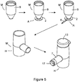
- Figure 5 shows assembly steps for manufacturing an aerosol generator assembly of the present invention in which medication cup M is bonded to the piezo ceramic actuator A with dome shaped nozzle plate 1 sandwiched between the rim 10 of the medication cup M and the annular piezo ceramic body 2. Electrical connector leads 6 are then connected to the electrical contact material 3 on the upper and lower surfaces of the annular piezo ceramic body 2.
- the housing H is then assembled around the medication cup M/ piezo ceramic actuator A sub-assembly. Cap 13 can then be fitted to the device as required.
- a power cable is inserted into the mouth 17 of the plug adapter 8 to provide electrical power to the aerosol generator assembly N.
- Liquid medicament to be dispensed is placed into the medication cup M.
- the liquid fills the funnel shaped inner chamber of medication cup M and rests over the dome shaped nozzle/membrane plate 1.
- Cap 13 may then be placed over the upper mouth of medication cup M so that the liquid medicament does not spill out of the aerosol generator assembly N.
- Power is turned on and flows through the electrical contact material of the upper and lower surfaces of the annular piezo ceramic body 2 to produce oscillations in the annular piezo ceramic body 2 which are transferred to dome shaped nozzle/membrane plate 1, to induce a vertical flexing action in the membrane plate 1.
- the flexing motion forces fluid at the upper surface of the dome shaped nozzle/membrane plate 1 through funnel shaped apertures in the dome shaped nozzle/membrane plate 1 by way of a micropumping action.
- the liquid exits the apertures in dome shaped nozzle/membrane plate 1 as an aerosol.
- the shape of inverted funnel shaped ejection cup E allows the generated aerosol to flow more efficiently out of the device. Ingress of moisture along the dome shaped nozzle/membrane plate 1 does not reach electrically contact material electrical contact material 3 easily due to the electrical contact material gap G between the mounting area of dome shaped nozzle/membrane plate 1 to the annular piezo ceramic body 2 and sealant provided therein.
Landscapes
- Health & Medical Sciences (AREA)
- Engineering & Computer Science (AREA)
- Anesthesiology (AREA)
- Biomedical Technology (AREA)
- Heart & Thoracic Surgery (AREA)
- Hematology (AREA)
- Life Sciences & Earth Sciences (AREA)
- Animal Behavior & Ethology (AREA)
- General Health & Medical Sciences (AREA)
- Public Health (AREA)
- Veterinary Medicine (AREA)
- Bioinformatics & Cheminformatics (AREA)
- Pulmonology (AREA)
- Special Spraying Apparatus (AREA)
Claims (11)
- Eine Aerosolgeneratoranordnung (N), die Folgendes aufweist:einen vibrierbaren piezo-keramischen Körper (2), der erste und zweite entgegengesetzte Seiten besitzt, eine Öffnung (0), die in dem vibrierbaren piezo-keramischen Körper definiert ist und sich von der ersten Seite zur zweiten Seite durch den Körper erstreckt und eine Schicht aus elektrischem Kontaktmaterial (3) auf jeder Seite des vibrierbaren piezo-keramischen Körpers besitzt, wobei der vibrierbaren piezo-keramische Körper durch Anlegen eines elektrischen Signals daran vibrierbar ist;ein vibrierbares Glied (1) mit darin definierten Poren, wobei das vibrierbare Glied (1) über der Öffnung (0) angebracht ist; und an wenigstens einer Seite des vibrierbaren piezo-keramischen Körpers um die Öffnung eine elektrische Kontaktmaterial-Freizone (4) vorgesehen ist,dadurch gekennzeichnet, dass die elektrische Kontaktmaterial-Freizone (4) und das vibrierbare Glied (1) so bemessen sind, dass das vibrierbare Glied oben auf dem vibrierbaren piezo-keramischen Körper (2) innerhalb der elektrischen Kontaktmaterial-Freizone (4) so angebracht ist, dass ein Spaltbereich (G) frei von elektrischem Kontaktmaterial (3) zwischen einer Abschlusskante der Schicht aus elektrischem Kontakmaterial (3) und dem Umfang des vibrierbaren Glieds (1) gebildet ist.
- Aerosolgeneratoranordnung (N) gemäß Anspruch 1, wobei die Schicht aus elektrischem Kontaktmaterial (3) einen Film von leitfähigem Material, der auf die Oberfläche des vibrierbaren piezo-keramischen Körpers (2) aufgebracht ist, aufweist.
- Aerosolgeneratoranordnung (N) nach Anspruch 2, wobei die elektrische Kontaktfreizone (4) auf dem vibrierbaren piezo-keramischen Körper (2) um die Öffnung (0) vorgesehen ist, um darin auf derselben Seite des vibrierbaren piezo-keramischen Körpers einen Oberflächenbereich vorzusehen, der mit dem Film aus leitfähigem Material überzogen ist und einen Oberflächenbereich, der nicht mit dem Film aus leitfähigem Material überzogen ist, auf dem das vibrierbare Glied (1) angebracht werden kann.
- Aerosolgeneratoranordnung (N) gemäß einem der Ansprüche 1 bis 3, wobei das vibrierbare Glied (1) mit dem vibrierbaren piezo-keramischen Körper (2) auf der Oberseite der elektrischen Kontaktmaterial-Freizone (4), vorgesehen um die Öffnung (0) darin, in Eingriff steht und dadurch die Öffnung auf einer Seite des vibrierbaren piezo-keramischen Körpers abdeckt.
- Aerosolgeneratoranordnung (N) gemäß einem der vorhergehenden Ansprüche, wobei das vibrierbare Glied (1) eine Randkante (5) aufweist, die auf dem vibrierbaren Körper innerhalb der elektrischen Kontaktmaterial-Freizone angebracht ist, um einen Spaltbereich (G) zu bilden.
- Aerosolgeneratoranordnung (N) gemäß einem der Ansprüche 1 bis 5, die ferner einen Bereitstellungsbecher, wie beispielsweise einen Arzneibecher (M) aufweist, der ein Mundstück besitzt, das so dimensioniert ist, dass es mit dem vibrierbaren piezo-keramischen Körper (2) um die Öffnung (0) zusammenpasst und auf dem vibrierbaren piezo-keramischen Körper angebracht ist durch Befestigen des Mundstücks davon an den vibrierbaren piezo-keramischen Körper, wobei der Bereitstellungsbecher ein Reservoir für Flüssigkeit bildet, die durch das vibrierbare Glied aerosoliert werden soll, dadurch gekennzeichnet, dass der vibrierbare piezo-keramische Körper einen Spalt oder eine Grenze der elektrischen Kontaktmaterial-Freizone (4) um das vibrierbare Glied (1) aufweist, dem oder die das vibrierbare Glied nicht einnimmt und auf dem oder der das Mundstück des Bereitstellungsbechers angebracht ist.
- Aerosolgeneratoranordnung (N) gemäß einem der Ansprüche 1 bis 6, die ferner einen Auswurfbecher (E) aufweist, der ein Mundstück besitzt, das so dimensioniert ist, dass es mit dem vibrierbaren piezo-keramischen Körper (2) um die Öffnung (0) zusammenpasst und auf dem vibrierbaren piezo-keramischen Körper angebracht ist durch Befestigen des Mundstücks davon an den vibrierbaren piezo-keramischen Körper, wobei der Auswurfsbecher eine Auswurfführung für ausgeworfene Flüssigkeit bildet, die durch das vibrierbare Glied aerosoliert wird.
- Aerosolgeneratoranordnung (N) gemäß einem der Ansprüche 6 oder 7, wobei das Mundstück des Bereitstellungsbechers so dimensioniert ist, dass er mit dem vibrierbaren Körper um die Öffnung und innerhalb der elektrischen Kontaktfreizone zusammenpasst.
- Aerosolgeneratoranordnung (N) gemäß einem der Ansprüche 6 bis 8, wobei der Bereitstellungsbechers an dem vibrierbaren piezo-keramischen Körper (2) mit einer Dichtung angebracht ist, die zwischen dem Mundstück des Bereitstellungsbechers und dem vibrierbaren piezo-keramischen Körper vorgesehen ist.
- Aerosolgeneratoranordnung (N) gemäß einem der vorhergehenden Ansprüche, wobei ein Dichtungsmaterial innerhalb der elektrischen Kontaktfreizone (4) vorgesehen ist.
- Aerosolgeneratoranordnung (N) gemäß einem der vorhergehenden Ansprüche, versehen mit elektrischen Kontaktverbindern (6) zum Kontaktieren des elektrischen Kontaktmaterials (3) an entgegengesetzten Seiten des vibrierbaren Körpers.
Priority Applications (1)
| Application Number | Priority Date | Filing Date | Title |
|---|---|---|---|
| EP11718125.5A EP2569033B1 (de) | 2010-05-13 | 2011-05-10 | Aerosolgeneratoranordnung |
Applications Claiming Priority (3)
| Application Number | Priority Date | Filing Date | Title |
|---|---|---|---|
| EP10162791 | 2010-05-13 | ||
| PCT/EP2011/057547 WO2011141475A1 (en) | 2010-05-13 | 2011-05-10 | Aerosol generator assembly |
| EP11718125.5A EP2569033B1 (de) | 2010-05-13 | 2011-05-10 | Aerosolgeneratoranordnung |
Publications (2)
| Publication Number | Publication Date |
|---|---|
| EP2569033A1 EP2569033A1 (de) | 2013-03-20 |
| EP2569033B1 true EP2569033B1 (de) | 2017-11-15 |
Family
ID=42358207
Family Applications (1)
| Application Number | Title | Priority Date | Filing Date |
|---|---|---|---|
| EP11718125.5A Active EP2569033B1 (de) | 2010-05-13 | 2011-05-10 | Aerosolgeneratoranordnung |
Country Status (6)
| Country | Link |
|---|---|
| US (1) | US9339838B2 (de) |
| EP (1) | EP2569033B1 (de) |
| AU (1) | AU2011252026B2 (de) |
| CA (1) | CA2798883C (de) |
| ES (1) | ES2654582T3 (de) |
| WO (1) | WO2011141475A1 (de) |
Families Citing this family (29)
| Publication number | Priority date | Publication date | Assignee | Title |
|---|---|---|---|---|
| EP3308865B1 (de) | 2010-10-04 | 2020-12-16 | Stamford Devices Limited | Aerosolerzeuger |
| TWM450428U (zh) * | 2012-10-19 | 2013-04-11 | Microbase Technology Corp | 噴孔片改良之霧化裝置 |
| TWI539978B (zh) * | 2013-09-13 | 2016-07-01 | 台達電子工業股份有限公司 | 微霧化裝置及其給藥室模組 |
| US9937302B2 (en) | 2013-09-13 | 2018-04-10 | Delta Electronics, Inc. | Nebulizing device and nebulizer |
| US10420903B2 (en) * | 2015-02-16 | 2019-09-24 | Microbase Technology Corp. | Aerosol generating apparatus with interchangeable parts |
| GB201518337D0 (en) * | 2015-10-16 | 2015-12-02 | The Technology Partnership Plc | Linear device |
| EP3272426B1 (de) * | 2016-07-19 | 2020-09-30 | Microbase Technology Corp. | Zerstäubungsvorrichtung |
| CN106377821A (zh) * | 2016-10-12 | 2017-02-08 | 盐城工学院 | 一种压电陶瓷雾化装置 |
| US11245235B2 (en) | 2016-11-11 | 2022-02-08 | Altria Client Services Llc | Electronic vaping device and connector assembly |
| CN208354595U (zh) * | 2018-04-11 | 2019-01-11 | 微邦科技股份有限公司 | 雾化液容器及其进排气件 |
| CN110393837B (zh) | 2018-04-25 | 2022-03-29 | 微邦科技股份有限公司 | 微雾产生器及雾化模块 |
| CN110394268B (zh) * | 2018-04-25 | 2021-07-02 | 微邦科技股份有限公司 | 微雾生成装置及微雾产生器 |
| US20200060338A1 (en) | 2018-08-22 | 2020-02-27 | Respira Technologies, Inc. | Electronic device for producing an aerosol for inhalation by a person |
| US11517685B2 (en) | 2019-01-18 | 2022-12-06 | Qnovia, Inc. | Electronic device for producing an aerosol for inhalation by a person |
| US12501929B2 (en) | 2018-08-22 | 2025-12-23 | Qnovia, Inc. | Electronic device for producing an aerosol for inhalation by a person |
| US11690963B2 (en) | 2018-08-22 | 2023-07-04 | Qnovia, Inc. | Electronic device for producing an aerosol for inhalation by a person |
| US20210052833A1 (en) * | 2019-08-22 | 2021-02-25 | Convexity Scientific Inc. | Mouthpiece of a nebulizer, and portable nebulizer thereof |
| US20210113783A1 (en) | 2019-10-20 | 2021-04-22 | Respira Technologies, Inc. | Electronic devices and liquids for aerosolizing and inhaling therewith |
| EP4044838A4 (de) * | 2019-10-20 | 2024-01-24 | Qnovia, Inc. | Elektronische vorrichtungen zum vernebeln und inhalieren von flüssigkeiten |
| JP7725492B2 (ja) * | 2020-03-11 | 2025-08-19 | フィリップ・モーリス・プロダクツ・ソシエテ・アノニム | エアロゾル発生装置およびシステム |
| US11298472B2 (en) * | 2020-04-24 | 2022-04-12 | SOSD Health & Medical Innovations Inc. | Ultrasonic nebulizer |
| WO2022082515A1 (zh) * | 2020-10-21 | 2022-04-28 | 深圳麦克韦尔科技有限公司 | 微孔雾化片以及超声雾化装置 |
| US12471625B2 (en) | 2020-11-01 | 2025-11-18 | Qnovia, Inc. | Electronic devices and liquids for aerosolizing and inhaling therewith |
| TWI747773B (zh) * | 2021-03-25 | 2021-11-21 | 心誠鎂行動醫電股份有限公司 | 給藥容器以及霧化裝置 |
| CA3261770A1 (en) | 2022-04-22 | 2023-10-26 | Qnovia, Inc. | ELECTRONIC DEVICES FOR VAPORIZING AND INHALATING LIQUID |
| US11850356B1 (en) * | 2023-06-08 | 2023-12-26 | Microneb Tech Holdings, Inc. | Apparatus, methods, and systems for administering a medication to a patient from a capsule using an atomizer |
| US11844900B1 (en) * | 2023-06-08 | 2023-12-19 | Microneb Tech Holdings, Inc. | Apparatus, methods, and systems for administering a medication to a patient from a capsule using an atomizer |
| US11944742B1 (en) * | 2023-06-08 | 2024-04-02 | Microneb Tech Holdings, Inc. | Apparatus, methods, and systems for administering a medication to an animal |
| US11925748B1 (en) * | 2023-06-08 | 2024-03-12 | Microneb Tech Holdings, Inc. | Apparatus, methods, and systems for administering a medication to a patient from a capsule using an atomizer |
Family Cites Families (12)
| Publication number | Priority date | Publication date | Assignee | Title |
|---|---|---|---|---|
| AU665222B2 (en) | 1991-12-04 | 1995-12-21 | Technology Partnership Plc, The | Production of fluid droplets |
| GB9412669D0 (en) | 1994-06-23 | 1994-08-10 | The Technology Partnership Plc | Liquid spray apparatus |
| GB9827262D0 (en) | 1998-12-10 | 1999-02-03 | The Technology Parternership Plc | Switchable spray generator and method of operation |
| ATE298600T1 (de) * | 2001-10-18 | 2005-07-15 | Pari Gmbh | Inhalationstherapievorrichtung |
| DE10250625A1 (de) * | 2002-10-30 | 2004-05-19 | Pari GmbH Spezialisten für effektive Inhalation | Inhalationstherapievorrichtung |
| US8616195B2 (en) * | 2003-07-18 | 2013-12-31 | Novartis Ag | Nebuliser for the production of aerosolized medication |
| DE102004016985B4 (de) * | 2004-04-07 | 2010-07-22 | Pari Pharma Gmbh | Aerosolerzeugungsvorrichtung und Inhalationsvorrichtung |
| DE102005006374B3 (de) * | 2005-02-11 | 2006-07-20 | Pari GmbH Spezialisten für effektive Inhalation | Aerosolerzeugungsvorrichtung und Inhalationstherapiegerät mit einer derartigen Vorrichtung |
| DE102005006375B4 (de) | 2005-02-11 | 2007-10-11 | Pari GmbH Spezialisten für effektive Inhalation | Aerosolerzeugungsvorrichtung für Inhalationstherapiegeräte |
| WO2006125677A1 (en) * | 2005-05-25 | 2006-11-30 | L'oreal | Piezoelectric spray device |
| EP2203155A1 (de) | 2007-09-25 | 2010-07-07 | Novartis Ag | Behandlung von lungenerkrankungen mit medikamenten in aerosolform wie vancomycin |
| EP2298230A1 (de) | 2009-09-21 | 2011-03-23 | Nortev Limited | Inhalationsmaske für Tiere |
-
2011
- 2011-05-10 EP EP11718125.5A patent/EP2569033B1/de active Active
- 2011-05-10 AU AU2011252026A patent/AU2011252026B2/en active Active
- 2011-05-10 CA CA2798883A patent/CA2798883C/en active Active
- 2011-05-10 ES ES11718125.5T patent/ES2654582T3/es active Active
- 2011-05-10 WO PCT/EP2011/057547 patent/WO2011141475A1/en not_active Ceased
- 2011-05-10 US US13/697,517 patent/US9339838B2/en active Active
Non-Patent Citations (1)
| Title |
|---|
| None * |
Also Published As
| Publication number | Publication date |
|---|---|
| US20130119151A1 (en) | 2013-05-16 |
| AU2011252026B2 (en) | 2015-09-03 |
| WO2011141475A1 (en) | 2011-11-17 |
| CA2798883C (en) | 2017-10-17 |
| AU2011252026A1 (en) | 2012-11-29 |
| CA2798883A1 (en) | 2011-11-17 |
| US9339838B2 (en) | 2016-05-17 |
| EP2569033A1 (de) | 2013-03-20 |
| ES2654582T3 (es) | 2018-02-14 |
Similar Documents
| Publication | Publication Date | Title |
|---|---|---|
| CA2798883C (en) | Aerosol generator assembly | |
| US12409282B2 (en) | Vibration systems and methods | |
| EP1509259B1 (de) | Gerät zur bereitstellung eines aerosols für die medizinische behandlung und verfahren | |
| US20100319685A1 (en) | Medical liquid droplet apparatus | |
| CN105966068B (zh) | 头以及液体喷射装置 | |
| EP4225509B1 (de) | Aerosolgenerator für eine inhalationsvorrichtung | |
| TW201803616A (zh) | 微霧化裝置 | |
| WO2007134240A2 (en) | Buried heater in printhead module | |
| CN112246517A (zh) | 微孔雾化片以及超声雾化装置 | |
| US20100288270A1 (en) | Liquid ejecting head | |
| CN214234714U (zh) | 微孔雾化片以及超声雾化装置 | |
| JP7511617B2 (ja) | 微孔性霧化部品及び電子霧化装置 | |
| WO2022082515A1 (zh) | 微孔雾化片以及超声雾化装置 | |
| CA3197653C (en) | Aerosol generator for an inhalation device | |
| HK40099147B (en) | Aerosol generator for an inhalation device | |
| KR20250159505A (ko) | 정전분무 노즐 필름 및 이를 이용한 정전분무 모듈 | |
| JP2009137211A (ja) | 液体噴射ヘッド、及び、液体噴射装置 | |
| JPH0223223B2 (de) |
Legal Events
| Date | Code | Title | Description |
|---|---|---|---|
| PUAI | Public reference made under article 153(3) epc to a published international application that has entered the european phase |
Free format text: ORIGINAL CODE: 0009012 |
|
| 17P | Request for examination filed |
Effective date: 20121112 |
|
| AK | Designated contracting states |
Kind code of ref document: A1 Designated state(s): AL AT BE BG CH CY CZ DE DK EE ES FI FR GB GR HR HU IE IS IT LI LT LU LV MC MK MT NL NO PL PT RO RS SE SI SK SM TR |
|
| DAX | Request for extension of the european patent (deleted) | ||
| 17Q | First examination report despatched |
Effective date: 20160224 |
|
| GRAP | Despatch of communication of intention to grant a patent |
Free format text: ORIGINAL CODE: EPIDOSNIGR1 |
|
| INTG | Intention to grant announced |
Effective date: 20170622 |
|
| GRAS | Grant fee paid |
Free format text: ORIGINAL CODE: EPIDOSNIGR3 |
|
| GRAA | (expected) grant |
Free format text: ORIGINAL CODE: 0009210 |
|
| RIN1 | Information on inventor provided before grant (corrected) |
Inventor name: O'SULLIVAN, GAVAN Inventor name: MORAN, DECLAN |
|
| AK | Designated contracting states |
Kind code of ref document: B1 Designated state(s): AL AT BE BG CH CY CZ DE DK EE ES FI FR GB GR HR HU IE IS IT LI LT LU LV MC MK MT NL NO PL PT RO RS SE SI SK SM TR |
|
| REG | Reference to a national code |
Ref country code: CH Ref legal event code: EP Ref country code: GB Ref legal event code: FG4D Ref country code: AT Ref legal event code: REF Ref document number: 945664 Country of ref document: AT Kind code of ref document: T Effective date: 20171115 |
|
| REG | Reference to a national code |
Ref country code: IE Ref legal event code: FG4D |
|
| REG | Reference to a national code |
Ref country code: CH Ref legal event code: NV Representative=s name: R.A. EGLI AND CO, PATENTANWAELTE, CH |
|
| REG | Reference to a national code |
Ref country code: DE Ref legal event code: R096 Ref document number: 602011043336 Country of ref document: DE Ref country code: FR Ref legal event code: PLFP Year of fee payment: 8 |
|
| REG | Reference to a national code |
Ref country code: SE Ref legal event code: TRGR |
|
| REG | Reference to a national code |
Ref country code: NL Ref legal event code: FP |
|
| REG | Reference to a national code |
Ref country code: ES Ref legal event code: FG2A Ref document number: 2654582 Country of ref document: ES Kind code of ref document: T3 Effective date: 20180214 |
|
| REG | Reference to a national code |
Ref country code: LT Ref legal event code: MG4D |
|
| REG | Reference to a national code |
Ref country code: AT Ref legal event code: MK05 Ref document number: 945664 Country of ref document: AT Kind code of ref document: T Effective date: 20171115 |
|
| PG25 | Lapsed in a contracting state [announced via postgrant information from national office to epo] |
Ref country code: FI Free format text: LAPSE BECAUSE OF FAILURE TO SUBMIT A TRANSLATION OF THE DESCRIPTION OR TO PAY THE FEE WITHIN THE PRESCRIBED TIME-LIMIT Effective date: 20171115 Ref country code: LT Free format text: LAPSE BECAUSE OF FAILURE TO SUBMIT A TRANSLATION OF THE DESCRIPTION OR TO PAY THE FEE WITHIN THE PRESCRIBED TIME-LIMIT Effective date: 20171115 Ref country code: NO Free format text: LAPSE BECAUSE OF FAILURE TO SUBMIT A TRANSLATION OF THE DESCRIPTION OR TO PAY THE FEE WITHIN THE PRESCRIBED TIME-LIMIT Effective date: 20180215 |
|
| PG25 | Lapsed in a contracting state [announced via postgrant information from national office to epo] |
Ref country code: LV Free format text: LAPSE BECAUSE OF FAILURE TO SUBMIT A TRANSLATION OF THE DESCRIPTION OR TO PAY THE FEE WITHIN THE PRESCRIBED TIME-LIMIT Effective date: 20171115 Ref country code: HR Free format text: LAPSE BECAUSE OF FAILURE TO SUBMIT A TRANSLATION OF THE DESCRIPTION OR TO PAY THE FEE WITHIN THE PRESCRIBED TIME-LIMIT Effective date: 20171115 Ref country code: AT Free format text: LAPSE BECAUSE OF FAILURE TO SUBMIT A TRANSLATION OF THE DESCRIPTION OR TO PAY THE FEE WITHIN THE PRESCRIBED TIME-LIMIT Effective date: 20171115 Ref country code: GR Free format text: LAPSE BECAUSE OF FAILURE TO SUBMIT A TRANSLATION OF THE DESCRIPTION OR TO PAY THE FEE WITHIN THE PRESCRIBED TIME-LIMIT Effective date: 20180216 Ref country code: RS Free format text: LAPSE BECAUSE OF FAILURE TO SUBMIT A TRANSLATION OF THE DESCRIPTION OR TO PAY THE FEE WITHIN THE PRESCRIBED TIME-LIMIT Effective date: 20171115 Ref country code: BG Free format text: LAPSE BECAUSE OF FAILURE TO SUBMIT A TRANSLATION OF THE DESCRIPTION OR TO PAY THE FEE WITHIN THE PRESCRIBED TIME-LIMIT Effective date: 20180215 |
|
| PG25 | Lapsed in a contracting state [announced via postgrant information from national office to epo] |
Ref country code: EE Free format text: LAPSE BECAUSE OF FAILURE TO SUBMIT A TRANSLATION OF THE DESCRIPTION OR TO PAY THE FEE WITHIN THE PRESCRIBED TIME-LIMIT Effective date: 20171115 Ref country code: CY Free format text: LAPSE BECAUSE OF FAILURE TO SUBMIT A TRANSLATION OF THE DESCRIPTION OR TO PAY THE FEE WITHIN THE PRESCRIBED TIME-LIMIT Effective date: 20171115 Ref country code: CZ Free format text: LAPSE BECAUSE OF FAILURE TO SUBMIT A TRANSLATION OF THE DESCRIPTION OR TO PAY THE FEE WITHIN THE PRESCRIBED TIME-LIMIT Effective date: 20171115 Ref country code: SK Free format text: LAPSE BECAUSE OF FAILURE TO SUBMIT A TRANSLATION OF THE DESCRIPTION OR TO PAY THE FEE WITHIN THE PRESCRIBED TIME-LIMIT Effective date: 20171115 Ref country code: DK Free format text: LAPSE BECAUSE OF FAILURE TO SUBMIT A TRANSLATION OF THE DESCRIPTION OR TO PAY THE FEE WITHIN THE PRESCRIBED TIME-LIMIT Effective date: 20171115 |
|
| REG | Reference to a national code |
Ref country code: DE Ref legal event code: R097 Ref document number: 602011043336 Country of ref document: DE |
|
| PG25 | Lapsed in a contracting state [announced via postgrant information from national office to epo] |
Ref country code: PL Free format text: LAPSE BECAUSE OF FAILURE TO SUBMIT A TRANSLATION OF THE DESCRIPTION OR TO PAY THE FEE WITHIN THE PRESCRIBED TIME-LIMIT Effective date: 20171115 Ref country code: RO Free format text: LAPSE BECAUSE OF FAILURE TO SUBMIT A TRANSLATION OF THE DESCRIPTION OR TO PAY THE FEE WITHIN THE PRESCRIBED TIME-LIMIT Effective date: 20171115 Ref country code: SM Free format text: LAPSE BECAUSE OF FAILURE TO SUBMIT A TRANSLATION OF THE DESCRIPTION OR TO PAY THE FEE WITHIN THE PRESCRIBED TIME-LIMIT Effective date: 20171115 |
|
| PLBE | No opposition filed within time limit |
Free format text: ORIGINAL CODE: 0009261 |
|
| STAA | Information on the status of an ep patent application or granted ep patent |
Free format text: STATUS: NO OPPOSITION FILED WITHIN TIME LIMIT |
|
| 26N | No opposition filed |
Effective date: 20180817 |
|
| PG25 | Lapsed in a contracting state [announced via postgrant information from national office to epo] |
Ref country code: SI Free format text: LAPSE BECAUSE OF FAILURE TO SUBMIT A TRANSLATION OF THE DESCRIPTION OR TO PAY THE FEE WITHIN THE PRESCRIBED TIME-LIMIT Effective date: 20171115 |
|
| PG25 | Lapsed in a contracting state [announced via postgrant information from national office to epo] |
Ref country code: MC Free format text: LAPSE BECAUSE OF FAILURE TO SUBMIT A TRANSLATION OF THE DESCRIPTION OR TO PAY THE FEE WITHIN THE PRESCRIBED TIME-LIMIT Effective date: 20171115 |
|
| PG25 | Lapsed in a contracting state [announced via postgrant information from national office to epo] |
Ref country code: LU Free format text: LAPSE BECAUSE OF NON-PAYMENT OF DUE FEES Effective date: 20180510 |
|
| PG25 | Lapsed in a contracting state [announced via postgrant information from national office to epo] |
Ref country code: MT Free format text: LAPSE BECAUSE OF NON-PAYMENT OF DUE FEES Effective date: 20180510 |
|
| PG25 | Lapsed in a contracting state [announced via postgrant information from national office to epo] |
Ref country code: TR Free format text: LAPSE BECAUSE OF FAILURE TO SUBMIT A TRANSLATION OF THE DESCRIPTION OR TO PAY THE FEE WITHIN THE PRESCRIBED TIME-LIMIT Effective date: 20171115 |
|
| PG25 | Lapsed in a contracting state [announced via postgrant information from national office to epo] |
Ref country code: HU Free format text: LAPSE BECAUSE OF FAILURE TO SUBMIT A TRANSLATION OF THE DESCRIPTION OR TO PAY THE FEE WITHIN THE PRESCRIBED TIME-LIMIT; INVALID AB INITIO Effective date: 20110510 Ref country code: PT Free format text: LAPSE BECAUSE OF FAILURE TO SUBMIT A TRANSLATION OF THE DESCRIPTION OR TO PAY THE FEE WITHIN THE PRESCRIBED TIME-LIMIT Effective date: 20171115 |
|
| PG25 | Lapsed in a contracting state [announced via postgrant information from national office to epo] |
Ref country code: MK Free format text: LAPSE BECAUSE OF NON-PAYMENT OF DUE FEES Effective date: 20171115 |
|
| PG25 | Lapsed in a contracting state [announced via postgrant information from national office to epo] |
Ref country code: AL Free format text: LAPSE BECAUSE OF FAILURE TO SUBMIT A TRANSLATION OF THE DESCRIPTION OR TO PAY THE FEE WITHIN THE PRESCRIBED TIME-LIMIT Effective date: 20171115 Ref country code: IS Free format text: LAPSE BECAUSE OF FAILURE TO SUBMIT A TRANSLATION OF THE DESCRIPTION OR TO PAY THE FEE WITHIN THE PRESCRIBED TIME-LIMIT Effective date: 20180315 |
|
| PGFP | Annual fee paid to national office [announced via postgrant information from national office to epo] |
Ref country code: NL Payment date: 20250521 Year of fee payment: 15 |
|
| PGFP | Annual fee paid to national office [announced via postgrant information from national office to epo] |
Ref country code: DE Payment date: 20250402 Year of fee payment: 15 |
|
| PGFP | Annual fee paid to national office [announced via postgrant information from national office to epo] |
Ref country code: GB Payment date: 20250402 Year of fee payment: 15 Ref country code: ES Payment date: 20250605 Year of fee payment: 15 |
|
| PGFP | Annual fee paid to national office [announced via postgrant information from national office to epo] |
Ref country code: IT Payment date: 20250409 Year of fee payment: 15 Ref country code: BE Payment date: 20250526 Year of fee payment: 15 |
|
| PGFP | Annual fee paid to national office [announced via postgrant information from national office to epo] |
Ref country code: FR Payment date: 20250401 Year of fee payment: 15 |
|
| PGFP | Annual fee paid to national office [announced via postgrant information from national office to epo] |
Ref country code: IE Payment date: 20250401 Year of fee payment: 15 |
|
| PGFP | Annual fee paid to national office [announced via postgrant information from national office to epo] |
Ref country code: SE Payment date: 20250401 Year of fee payment: 15 |
|
| PGFP | Annual fee paid to national office [announced via postgrant information from national office to epo] |
Ref country code: CH Payment date: 20250901 Year of fee payment: 15 |