EP3439793B1 - Aerosolerzeugungsvorrichtung - Google Patents
Aerosolerzeugungsvorrichtung Download PDFInfo
- Publication number
- EP3439793B1 EP3439793B1 EP17831732.7A EP17831732A EP3439793B1 EP 3439793 B1 EP3439793 B1 EP 3439793B1 EP 17831732 A EP17831732 A EP 17831732A EP 3439793 B1 EP3439793 B1 EP 3439793B1
- Authority
- EP
- European Patent Office
- Prior art keywords
- mating
- adaptor
- aerosol generating
- generating apparatus
- liquid container
- Prior art date
- Legal status (The legal status is an assumption and is not a legal conclusion. Google has not performed a legal analysis and makes no representation as to the accuracy of the status listed.)
- Active
Links
Images






Classifications
-
- A—HUMAN NECESSITIES
- A61—MEDICAL OR VETERINARY SCIENCE; HYGIENE
- A61M—DEVICES FOR INTRODUCING MEDIA INTO, OR ONTO, THE BODY; DEVICES FOR TRANSDUCING BODY MEDIA OR FOR TAKING MEDIA FROM THE BODY; DEVICES FOR PRODUCING OR ENDING SLEEP OR STUPOR
- A61M11/00—Sprayers or atomisers specially adapted for therapeutic purposes
- A61M11/005—Sprayers or atomisers specially adapted for therapeutic purposes using ultrasonics
-
- A—HUMAN NECESSITIES
- A61—MEDICAL OR VETERINARY SCIENCE; HYGIENE
- A61M—DEVICES FOR INTRODUCING MEDIA INTO, OR ONTO, THE BODY; DEVICES FOR TRANSDUCING BODY MEDIA OR FOR TAKING MEDIA FROM THE BODY; DEVICES FOR PRODUCING OR ENDING SLEEP OR STUPOR
- A61M15/00—Inhalators
- A61M15/0001—Details of inhalators; Constructional features thereof
-
- A—HUMAN NECESSITIES
- A61—MEDICAL OR VETERINARY SCIENCE; HYGIENE
- A61M—DEVICES FOR INTRODUCING MEDIA INTO, OR ONTO, THE BODY; DEVICES FOR TRANSDUCING BODY MEDIA OR FOR TAKING MEDIA FROM THE BODY; DEVICES FOR PRODUCING OR ENDING SLEEP OR STUPOR
- A61M15/00—Inhalators
- A61M15/0085—Inhalators using ultrasonics
-
- B—PERFORMING OPERATIONS; TRANSPORTING
- B05—SPRAYING OR ATOMISING IN GENERAL; APPLYING FLUENT MATERIALS TO SURFACES, IN GENERAL
- B05B—SPRAYING APPARATUS; ATOMISING APPARATUS; NOZZLES
- B05B15/00—Details of spraying plant or spraying apparatus not otherwise provided for; Accessories
- B05B15/14—Arrangements for preventing or controlling structural damage to spraying apparatus or its outlets, e.g. for breaking at desired places; Arrangements for handling or replacing damaged parts
- B05B15/18—Arrangements for preventing or controlling structural damage to spraying apparatus or its outlets, e.g. for breaking at desired places; Arrangements for handling or replacing damaged parts for improving resistance to wear, e.g. inserts or coatings; for indicating wear; for handling or replacing worn parts
-
- B—PERFORMING OPERATIONS; TRANSPORTING
- B05—SPRAYING OR ATOMISING IN GENERAL; APPLYING FLUENT MATERIALS TO SURFACES, IN GENERAL
- B05B—SPRAYING APPARATUS; ATOMISING APPARATUS; NOZZLES
- B05B17/00—Apparatus for spraying or atomising liquids or other fluent materials, not covered by the preceding groups
- B05B17/04—Apparatus for spraying or atomising liquids or other fluent materials, not covered by the preceding groups operating with special methods
- B05B17/06—Apparatus for spraying or atomising liquids or other fluent materials, not covered by the preceding groups operating with special methods using ultrasonic or other kinds of vibrations
- B05B17/0607—Apparatus for spraying or atomising liquids or other fluent materials, not covered by the preceding groups operating with special methods using ultrasonic or other kinds of vibrations generated by electrical means, e.g. piezoelectric transducers
- B05B17/0638—Apparatus for spraying or atomising liquids or other fluent materials, not covered by the preceding groups operating with special methods using ultrasonic or other kinds of vibrations generated by electrical means, e.g. piezoelectric transducers spray being produced by discharging the liquid or other fluent material through a plate comprising a plurality of orifices
- B05B17/0646—Vibrating plates, i.e. plates being directly subjected to the vibrations, e.g. having a piezoelectric transducer attached thereto
-
- B—PERFORMING OPERATIONS; TRANSPORTING
- B05—SPRAYING OR ATOMISING IN GENERAL; APPLYING FLUENT MATERIALS TO SURFACES, IN GENERAL
- B05B—SPRAYING APPARATUS; ATOMISING APPARATUS; NOZZLES
- B05B17/00—Apparatus for spraying or atomising liquids or other fluent materials, not covered by the preceding groups
- B05B17/04—Apparatus for spraying or atomising liquids or other fluent materials, not covered by the preceding groups operating with special methods
- B05B17/06—Apparatus for spraying or atomising liquids or other fluent materials, not covered by the preceding groups operating with special methods using ultrasonic or other kinds of vibrations
- B05B17/0607—Apparatus for spraying or atomising liquids or other fluent materials, not covered by the preceding groups operating with special methods using ultrasonic or other kinds of vibrations generated by electrical means, e.g. piezoelectric transducers
- B05B17/0653—Details
-
- A—HUMAN NECESSITIES
- A61—MEDICAL OR VETERINARY SCIENCE; HYGIENE
- A61M—DEVICES FOR INTRODUCING MEDIA INTO, OR ONTO, THE BODY; DEVICES FOR TRANSDUCING BODY MEDIA OR FOR TAKING MEDIA FROM THE BODY; DEVICES FOR PRODUCING OR ENDING SLEEP OR STUPOR
- A61M2205/00—General characteristics of the apparatus
- A61M2205/02—General characteristics of the apparatus characterised by a particular materials
- A61M2205/0272—Electro-active or magneto-active materials
- A61M2205/0294—Piezoelectric materials
-
- A—HUMAN NECESSITIES
- A61—MEDICAL OR VETERINARY SCIENCE; HYGIENE
- A61M—DEVICES FOR INTRODUCING MEDIA INTO, OR ONTO, THE BODY; DEVICES FOR TRANSDUCING BODY MEDIA OR FOR TAKING MEDIA FROM THE BODY; DEVICES FOR PRODUCING OR ENDING SLEEP OR STUPOR
- A61M2205/00—General characteristics of the apparatus
- A61M2205/12—General characteristics of the apparatus with interchangeable cassettes forming partially or totally the fluid circuit
- A61M2205/121—General characteristics of the apparatus with interchangeable cassettes forming partially or totally the fluid circuit interface between cassette and base
-
- A—HUMAN NECESSITIES
- A61—MEDICAL OR VETERINARY SCIENCE; HYGIENE
- A61M—DEVICES FOR INTRODUCING MEDIA INTO, OR ONTO, THE BODY; DEVICES FOR TRANSDUCING BODY MEDIA OR FOR TAKING MEDIA FROM THE BODY; DEVICES FOR PRODUCING OR ENDING SLEEP OR STUPOR
- A61M2205/00—General characteristics of the apparatus
- A61M2205/12—General characteristics of the apparatus with interchangeable cassettes forming partially or totally the fluid circuit
- A61M2205/123—General characteristics of the apparatus with interchangeable cassettes forming partially or totally the fluid circuit with incorporated reservoirs
Definitions
- Aerosolization is to be conducted after the liquid container 20 and the adaptor 30 is engaged.
- the relative position between the liquid container 20 and the adaptor 30 is fixed during aerosolization to ensure the liquid medicament is aerosolized under a controlled manner. Still, their relative position may be adjusted to configure the aerosolization rate based on different needs.
- FIG. 2 illustrates the aerosol generating apparatus 10 with the liquid container 20 disengaged from the adaptor 30. Further, relevant components accommodated by the liquid container 20 and the adaptor 30 are shown in an exploded view.
- the liquid container 20 includes a membrane 204 at its outlet opening. At least part of the membrane 204 is porous. That is, the membrane 204 includes a plurality of orifices 206 for the liquid medicament to eject. Therefore, the membrane 204 may also be referred to as a perforated membrane.
- Exemplary ways of forming the orifices 206 include etching or laser drilling.
- the orifices 206 can also be formed by other method known to persons having ordinary skill in the art.
- the size of the orifices 206 is configured to substantially prevent liquid medicament from leaking.
- the orifices 206 are positioned around the center of the membrane 204.
- the orifices 206 may be distributed all over the membrane 204 or at certain sections only, depending on the configuration of the rest of the components of the aerosol generating apparatus 10.
- a driving element 40 is accommodated by the adaptor 30.
- the driving element includes a piezoelectric (PZT) element (404, not shown) and a substrate 402.
- the substrate 402 may be flat or with a projection.
- the substrate 402 is made of metal or any kind of material suitable for prolonged vibration without breakage.
- the PZT element 404 is coupled to the liquid outlet side of the substrate 402, and the liquid inlet side of the substrate 402 faces the membrane 204.
- the substrate 402 and the membrane 204 are in contact.
- electric power is provided to the PZT element through electric contacts, such as wires or leads.
- FIG. 4 is an exploded view of part of the aerosol generating device according to some embodiments of the present disclosure.
- the substrate 402 may include a mating structure 410 that corresponds to the jack 308.
- the mating structure 410 may be an indention or recess corresponding to the shape of the jack 308.
- the aperture 406 may be directed to another predetermined position suitable for better aerosolization.
- the substrate 402 may become fitted with the jack 308 such that horizontal movement during aerosolization is reduced or inhibited.
- the electric contact 412 of the PZT element 404 is illustrated.
- Such electric contact 412 may be leads or electric wires. It is configured to provide electric power to the PZT element 404 to create vibration. Such vibration is then transmitted to the membrane 204 through the substrate 402 for aerosolization.
- the PZT element 404 is ring shaped so aerosolized liquid can pass through its central through hole.
- the shape of the PZT element 404 is not limited to circular and may be adjusted if needed.
- the shape of the PZT element 404 may not be a complete ring. It can be C-shaped or an incomplete ring with gaps.
- the PZT element 404 can be of any shape or form.
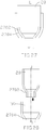
- FIGs. 5 - 7 are side views of part of an aerosol generating apparatus in accordance with some embodiments of the present disclosure.
- the mating structure 410 may be a tab protruding out of the periphery of the substrate 402.
- the corresponding supporting structure at the adaptor 30 would not be a jack or anything that protrudes out from the adaptor 30. Instead, it can be an indentation on the adaptor 30 to accommodate the protruding tab.
- the number, structure, placement or configuration of the mating/supporting structure between the substrate 402 and the adaptor 30 should not be limited to only the embodiments disclosed herein. A person having ordinary skill in the art would understand that any mechanism that provides minimal contact between the substrate 402 and the adaptor 30 at the periphery of the substrate 402 should fall within the scope of this disclosure.
- FIG. 6 shows another embodiment when the substrate 402 is not engaged with the adaptor 30.
- FIG. 7 shows the same embodiment when the substrate 402 is engaged with the adaptor 30. Particularly, FIG. 7 shows a cross-sectional view of the components along the dotted line D-D' in FIG. 6 but with the substrate 402 engaged with the adaptor 30.
- the substrate 402 is in contact with the adaptor 30 only at the jacks 308.
- the inner perimeter of the adaptor 30 surrounding the substrate 402 is not in contact with the substrate 402.
- a space is formed and maintained between the substrate 402 and the adaptor 30 except where the jack 308 is. As such, there's limited or minimal hindrance against the vibration of the substrate 402 by the adaptor 30.
- the resulting driving element 40 generates desired vibration energy with less electric power consumption.
- the liquid/aerosol flow direction from L to L' is again illustrated in FIG. 7 .
- the substrate 402 includes a first liquid inlet side facing the liquid container (not shown), and a first liquid outlet side facing the adaptor 30.
- the adaptor 30 includes a second liquid inlet side facing the liquid container (not shown) and a second liquid outlet side at the through hole 306 where aerosolized liquid leaves the adaptor 30.
- a space S1 is maintained between the first liquid outlet side and the second liquid inlet side such that the two sides will not touch each other during aerosolization.
- the space S1 also serves to ensure that there is enough room between the first liquid outlet side and the second liquid inlet side to accommodate the PZT element 404.
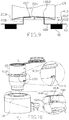
- FIGs. 8-9 are partial and lateral views of an aerosol generating apparatus with interchangeable parts in accordance with some embodiments of the present disclosure.
- FIG. 8 is a partial view of the aerosol generating apparatus 10 in the engaged state.
- the membrane 204 is in direct contact with but not pressed inward by the projection 408 extending from the face of the inlet surface 402 of the structure plate 40.
- the interface between the membrane 204 and the top surface of the projection 408 is substantially leveled.
- an additional layer such as a protection layer or a coating, may be provided between the membrane 204 and the projection 408. Still, as long as neither the transmission of vibration energy from the projection 408 to the membrane 204 nor the detachability of the projection 408 and the membrane 204 is affected, any layer may be added between the projection and the membrane and the two should still be considered as in direct contact.
- the projection 408 includes a top surface facing the membrane 204 when engaged, and the section of such top surface in contact with the membrane 204 is the working surface 4082.
- the working surface 4082 is the same size as the top surface of the projection 408.
- the working surface 4082 serves as the interface for transmitting the vibration energy from an oscillation generator 50 to the membrane 204 for aerosolization.
- the dimension, i.e., area, of the working surface 4082 is subject to change. The factors affecting its dimension may include size of the projection or the membrane, shape of the working surface, shape of the projection, extent of the membrane being pushed inward by the projection, material of the membrane, and so on.
- the dimension of the working surface 4082 may also be adjusted according to the purpose of the aerosol generating apparatus or the liquid medicament contained therein. In a preferred embodiment, the dimension of the working surface 4082 is not larger than that of the membrane 204 to ensure desired aerosolization efficiency.
- a space 410 is formed between the membrane 204 and the inlet surface 402.
- the space 410 is preserved because not the entire membrane 204 is in contact with the projection 408.
- vibration energy is transmitted from the oscillation generator 50 to the membrane 204 through the working surface 4082, those sections of the membrane 204 not in touch with or affected by the projection 408 are in free-form.
- being in "free-form” or "free-form movement” means that the vibration of the membrane 204 is not affected by undesirable influences of surrounding component(s) or structure(s) of the aerosol generating apparatus.
- a space 410' may be formed between the upper surface of the projection 408 and the membrane 204.
- the dimension of the working surface 4082 of the projection 408 is reduced because its area of contact with the membrane 204 is reduced. Still, as long as there is some working surface 4082 and vibration energy can be transmitted from the projection 408 to the membrane 204, such configuration is within the scope of the present disclosure.
- the distance D is less than the height H because not the entire projection 408 is pushed inward against the membrane 204. Thus, sections of the membrane 204 other than those in contact with the projection 408 are in free from and vibration of which is not affected by the projection 408 or the structure plate 40.
- the distance D can be adjusted pursuant to the need of the aerosol generating apparatus and the particle size of the liquid medicament.
- the height H of the projection 408 is no less than 0.1 mm in order to preserve the space 410 and the free-form movement of those sections not in contact with the structure plate 40 and/or the projection 408.
- the distance D is less than the height H to ensure that less than the entire projection 408 is pushed inward against membrane 204.
- FIGs. 10-14 schematically illustrate the liquid container 20 slidably and detachably mates and engages with the adaptor 30 via their respective mating elements according to some embodiments of the present disclosure.
- the liquid container 20 has a first mating element 1010.
- the adaptor 30 has a second mating element 1020 that can mate and engage with the first mating element 1010 in a mutually slidable and detachable manner.
- the second mating element may locate at either the body 302 or the interface 304.
- the first mating element 1010 may be a tongue.
- the second mating element 1020 may be a groove formed between a stopper 1080 and an inner edge 1014.
- the first mating element 1010 is adapted to slidably move along a sliding axis S into the receiving second mating element 1020 via the inner edge 1014.
- the stopper 1080 When the first mating element 1010 abuts the stopper 1080, a full mate condition is reached. In other words, the two mating elements are engaged and the liquid container 20 and adaptor 30 are locked. Note that the sliding movement is not limited to the first mating element 1010. Inversely, the second mating element may slidably move in the opposite direction to engage the first mating element.
- a third mating element 1030 may annuarly extend around the liquid container 20 in the shape of a protruding ring.
- a fourth mating element 1040 may locate at the top edge of the adaptor 30 to mate and engage the third mating element 1030.
- the fourth mating element 1040 may be a circular edge adapted to make contact with the protruding ring of the third mating element 1030 during mating operation, thereby preventing the third mating element (and the liquid container 20) from further downward movement.
- the third mating element is adapted to rest on the fourth mating element during engagement, allowing the vertical position of the liquid container 20 to maintain station.
- the first and second mating elements may slidably move to engage each other.
- a downward relative movement of the liquid container 20 along the dotted line from L to L' is initiated by a downward force F1.
- the third mating element 1030 mates with the fourth mating element 1040 by contacting or resting on the fourth mating element, while the first mating element sits on the inner edge 1014.
- the projection 408 of the substrate 402 may be in contact with the perforated membrane 204.
- the downward force F1 may be initiated by a user or by any mechanical means.
- FIG. 14 illustrates the successful engagement of the liquid container 20 and adaptor 30 where the perforated membrane 204 and the aperture 406 are properly aligned and the projection 408 presses against the perforated membrane 204.
- the extent in which the projection 408 presses the membrane 204 can be adjusted based on the position of the first and second mating elements 1010 and 1020 and/or the third and fourth mating elements 1030 and 1040, relative to the liquid container 20 and adaptor 30. For example, lowering the positions of the mating elements 1010 and 1020 will cause the projection 408 to press more against the perforated membrane 204, i.e., increasing the distance D. Conversely, raising the positions of the mating elements 1010 and 1020 will cause the projection 408 to press less against the perforated membrane 204, i.e., decreasing the distance D.
- FIGs. 15-20 illustrate other types of connection in which the first mating element 1010 and the second mating element 1020 can be engaged.
- the first mating element 1010 includes a helical threaded surface 1502 and the second mating element 1020 includes a helical threaded surface 1504.
- the helical threaded surface 1502 mates with the helical thread surface 1504 while the liquid container 20 rotates down along the direction of dotted line from L to L'.
- the liquid container 20 can no longer be rotated, either because the end of helical thread or a stopper is reached, a full mate condition is achieved and the liquid container 20 is affixed with the adaptor 30.
- the first mating element 1010 includes a groove 1702 and the second mating element 1020 includes a tongue 1704.
- the groove 1702 slidably mates with the tongue 1704 in a similar manner as described above.
- a full mate condition is reached.
- the first mating element 1010 includes a stopper 2102 and a helical threaded surface 2104
- the second mating element 1020 includes a helical threaded surface 2106.
- the helical threaded surface 2104 mates with the helical threaded surface 2106.
- the stopper 2102 makes contact with the upper edge of the second mating element 1020, it stops the liquid container 20 from rotating down further. A full mate condition is reached and the position of the liquid container 20 and adaptor 30 is fixed.
- connection mechanisms described involve either a sliding or a rotational movement.
- connection mechanisms that do not involve sliding or rotating movements are also applicable in the present invention, as illustrated in FIGs. 21 and 22 .
- the mating elements can mate and engage using a connection such as a snap fit, an interference fit, a (non-sliding) tongue-and-groove fit, a post-and-bore fit, or a press fit.
- the first mating element 1010 includes a protruding part 1902 and the second mating element 1020 includes a cavity 1904.
- the protruding part 1902 can be a hook, stud or bead.
- the protruding part 1902 is deflected briefly during the joining operation and catches in the mating cavity 1904 of the adaptor 30. After engagement, this snap-fit features should return to a stress-free condition.
- the engagement may be separable or inseparable depending on the shape of the cavity 1904.
- the extent in which the projection 408 presses against the membrane 204 may correspond to a relative movement of the first mating element 1010 (i.e., the protruding part 1902) in the longitudinal direction, i.e., along the dotted line from L to L'.
- distance D may correlate to how far the first mating element can move downward in respective to the adaptor 30.
- FIGs. 23-32 disclose other examples of the present disclosure that apply connection mechanisms similar to the one shown in FIGs. 21-22 .
- the first mating element 1010 includes a protruding part 2302 that extends annuarly around the liquid container 20, and the second mating element 1020 includes a cavity 2306.
- the protruding part 2302 mates and engages the cavity 2306 via an interference or press fit.
- the first mating element 1010 includes a protruding part 2502 that extend semi-annuarly around the liquid container 20, and the second mating element 1020 includes a mating cavity 2506.
- the two mating elements can be connected using an interference fit or press fit.
- the first mating element 1010 includes a contact surface 2702
- the second mating element 1020 includes a contact surface 2704.
- the contact surfaces 2702 and 2704 are adapted in a manner such that friction occurs between the two contact surfaces to create a friction or press-fit.
- the first mating element 1010 includes two protruding parts 2902 and 2904, and the second mating element 1020 includes two mating cavities 2906 and 2908.
- the two mating elements can be joined via a snap-fit configuration.
- the first mating element 1010 includes two cavities 3102 and 3104
- the second mating element 1020 includes two mating protruding parts 3106 and 3108.
- the two mating elements can be joined via a snap-fit configuration.
Landscapes
- Health & Medical Sciences (AREA)
- Engineering & Computer Science (AREA)
- Animal Behavior & Ethology (AREA)
- Anesthesiology (AREA)
- Biomedical Technology (AREA)
- Heart & Thoracic Surgery (AREA)
- Hematology (AREA)
- Life Sciences & Earth Sciences (AREA)
- General Health & Medical Sciences (AREA)
- Public Health (AREA)
- Veterinary Medicine (AREA)
- Pulmonology (AREA)
- Bioinformatics & Cheminformatics (AREA)
- Containers And Packaging Bodies Having A Special Means To Remove Contents (AREA)
- Special Spraying Apparatus (AREA)
Claims (15)
- Aerosol erzeugendes Gerät (10), umfassend:einen Flüssigkeitsbehälter (20), der eine perforierte Membran (204) beinhaltet, durch die eine Flüssigkeit durchdringen kann, wobei der Flüssigkeitsbehälter (20) ferner ein erstes Fügeelement (1010) beinhaltet;einen Adapter (30), der ein zweites Fügeelement (1020) beinhaltet; undein Antriebselement (40), das ein piezoelektrisches Element beinhaltet, das an ein Substrat (402) gekoppelt ist, wobei das Antriebselement (40) in dem Adapter (30) untergebracht ist und das Substrat (402) eine Öffnung (406) und einen Vorsprung (408) beinhaltet;wobei das erste und zweite Fügeelement (1010, 1020) dazu ausgelegt sind, sich lösbar miteinander derart zu fügen, dass die Öffnung (406) des Substrats (402) benachbart zu dem Zentrum der perforierten Membran (204) ausgerichtet ist,wobei der Vorsprung (408) dazu ausgelegt ist, gegen die perforierte Membran (204) zu pressen, wenn das erste und zweite Fügeelement (1010, 1020) miteinander eingreifen.
- Aerosol erzeugendes Gerät (10) nach Anspruch 1, wobei das erste und zweite Fügeelement (1010, 1020) dazu ausgelegt sind, unter Verwendung einer Verbindung miteinander einzugreifen, die ausgewählt ist aus der Gruppe bestehend aus einer Schnapppassung, einer Schrumpfpassung, einer Feder/Nut-Passung, einer Stift/Bohrung-Passung, und einer Presspassung.
- Aerosol erzeugendes Gerät (10) nach Anspruch 1, wobei das erste Fügeelement (1010) ferner dazu ausgelegt ist, sich in eine longitudinale Richtung zu bewegen, wobei vorzugsweise das Ausmaß, in dem die perforierte Membran (204) von dem Vorsprung (408) gepresst ist, mit einer relativen Bewegung des ersten Fügeelements (1010) in der longitudinalen Richtung korreliert.
- Aerosol erzeugendes Gerät (10) nach Anspruch 1, wobei der Adapter (30) ferner zumindest eine Buchse (308) zum Kontaktieren und Unterstützen des Substrats (402) umfasst.
- Aerosol erzeugendes Gerät (10) nach Anspruch 1, wobei das erste Fügeelement (1010) einen vorstehenden Teil (1902, 2302, 2502, 2902, 2904) beinhaltet und das zweite Fügeelement (1020) eine Kavität (1904, 2306, 2506, 3102, 3104) beinhaltet, wobei der vorstehende Teil (1902, 2302, 2502, 2902, 2904) während des Fügens kurzzeitig ausgelenkt ist und in die Kavität (1904, 2306, 2506, 3102, 3104) eingreift.
- Aerosol erzeugendes Gerät (10) nach Anspruch 5, wobei der vorstehende Teil (1902, 2302, 2502, 2902, 2904) ausgewählt ist aus der Gruppe bestehend aus einem Haken, einem Bolzen oder einer Kugel, oder
wobei sich der vorstehende Teil (1902, 2302, 2502, 2902, 2904) ringförmig um den Flüssigkeitsbehälter (20) herum erstreckt und sich die fügende Kavität (2906, 2908) ringförmig innerhalb des Adapters (30) erstreckt, oder
wobei sich der vorstehende Teil (1902, 2302, 2502, 2902, 2904) halbringförmig um den Flüssigkeitsbehälter (20) herum erstreckt und sich die fügende Kavität (2906, 2908) halbringförmig innerhalb des Adapters (30) erstreckt. - Aerosol erzeugendes Gerät (10) nach Anspruch 1, wobei das erste Fügeelement (1010) eine erste Kontaktierungsoberfläche beinhaltet und das zweite Fügeelement (1020) eine zweite Kontaktierungsoberfläche beinhaltet, wobei die erste und die zweite Kontaktierungsoberfläche dazu ausgelegt sind, Reibung derart zu erzeugen, dass der Flüssigkeitsbehälter (20) und der Adapter (30) in Eingriff sind.
- Aerosol erzeugendes Gerät (10) nach Anspruch 1, wobei das erste und das zweite Fügeelement (1010, 1020) dazu ausgelegt sind, gleitbar miteinander derart zu fügen, dass die Öffnung (406) des Substrats (402) benachbart zu dem Zentrum der perforierten Membran (204) ausgerichtet ist.
- Aerosol erzeugendes Gerät (10) nach Anspruch 1, wobei das erste und das zweite Fügeelement (1010, 1020) ferner für eine relative Bewegung entlang einer Gleitachse ausgelegt sind.
- Aerosol erzeugendes Gerät (10) nach Anspruch 1, wobei das erste und das zweite Fügeelement (1010, 1020) dazu ausgelegt sind, sich entlang einer Gleitachse zu bewegen bis eine vollständige Fügebedingung erreicht ist.
- Aerosol erzeugendes Gerät (10) nach Anspruch 1, wobei das erste Fügeelement (1010) eine Nut (1702) beinhaltet, die mit einer Fügefeder (1704) auf dem zweiten Fügeelement (1020) eingreift; oder
wobei das erste Fügeelement (1010) eine Feder (1704) beinhaltet, die mit einer Fügenut (1702) auf dem zweiten Fügeelement (1020) eingreift. - Aerosol erzeugendes Gerät (10) nach Anspruch 1, wobei der Adapter (30) ferner zumindest eine Buchse (308) zum Kontaktieren und Unterstützen des Substrats (402) umfasst.
- Aerosol erzeugendes Gerät (10) nach Anspruch 1, wobei der Flüssigkeitsbehälter (20) ein drittes Fügeelement (1030) beinhaltet, das dazu ausgelegt ist, den Flüssigkeitsbehälter (20) ringförmig zu umgeben, und wobei der Adapter (30) ein viertes Fügeelement (1040) beinhaltet, das dazu ausgelegt ist, sich an der Oberkante des Adapters (30) zu lokalisieren, wobei das dritte und das vierte Fügeelement (1030, 1040) dazu ausgelegt sind, miteinander derart zu fügen und einzugreifen, dass die vertikale Position des Flüssigkeitsbehälters (20) stationär gehalten wird, wobei vorzugsweise das dritte Fügeelement (1030) ein vorstehender Ring ist und das vierte Fügeelement (1040) eine kreisförmige Kante ist.
- Aerosol erzeugendes Gerät (10) nach Anspruch 1, wobei ein Ausmaß, in dem die perforierte Membran (204) von dem Vorsprung (408) gepresst ist, vorbestimmt ist von den Positionen des ersten und des zweiten Fügeelements (1010, 1020), oder wobei das erste Fügeelement (1010) eine spiralförmige Gewindeoberfläche (1502, 1504, 2104, 2016) beinhaltet, die rotierend mit einer fügenden spiralförmigen Gewindeoberfläche auf dem zweiten Fügeelement (1020) eingreift.
- Aerosol erzeugendes Gerät (10) nach Anspruch 1, wobei das erste Fügeelement (1010) einen Vorsprung beinhaltet und das zweite Fügeelement (1020) eine Kavität (1904, 2306, 2506, 3102, 3104) beinhaltet, wobei der Vorsprung in Folge eines Einsetzens des Flüssigkeitsbehälters (20) in den Adapter (30) temporär ausgelenkt ist und sich zurückbiegt, um in die Kavität (1904, 2306, 2506, 3102, 3104) einzugreifen.
Priority Applications (1)
| Application Number | Priority Date | Filing Date | Title |
|---|---|---|---|
| EP20185682.0A EP3769854B1 (de) | 2016-07-19 | 2017-07-19 | Aerosolerzeugungsvorrichtung |
Applications Claiming Priority (2)
| Application Number | Priority Date | Filing Date | Title |
|---|---|---|---|
| US201662364309P | 2016-07-19 | 2016-07-19 | |
| PCT/US2017/042687 WO2018017627A1 (en) | 2016-07-19 | 2017-07-19 | Aerosol generating apparatus |
Related Child Applications (2)
| Application Number | Title | Priority Date | Filing Date |
|---|---|---|---|
| EP20185682.0A Division-Into EP3769854B1 (de) | 2016-07-19 | 2017-07-19 | Aerosolerzeugungsvorrichtung |
| EP20185682.0A Division EP3769854B1 (de) | 2016-07-19 | 2017-07-19 | Aerosolerzeugungsvorrichtung |
Publications (3)
| Publication Number | Publication Date |
|---|---|
| EP3439793A1 EP3439793A1 (de) | 2019-02-13 |
| EP3439793A4 EP3439793A4 (de) | 2019-05-01 |
| EP3439793B1 true EP3439793B1 (de) | 2021-03-24 |
Family
ID=59381150
Family Applications (3)
| Application Number | Title | Priority Date | Filing Date |
|---|---|---|---|
| EP17831732.7A Active EP3439793B1 (de) | 2016-07-19 | 2017-07-19 | Aerosolerzeugungsvorrichtung |
| EP17182014.5A Active EP3272426B1 (de) | 2016-07-19 | 2017-07-19 | Zerstäubungsvorrichtung |
| EP20185682.0A Active EP3769854B1 (de) | 2016-07-19 | 2017-07-19 | Aerosolerzeugungsvorrichtung |
Family Applications After (2)
| Application Number | Title | Priority Date | Filing Date |
|---|---|---|---|
| EP17182014.5A Active EP3272426B1 (de) | 2016-07-19 | 2017-07-19 | Zerstäubungsvorrichtung |
| EP20185682.0A Active EP3769854B1 (de) | 2016-07-19 | 2017-07-19 | Aerosolerzeugungsvorrichtung |
Country Status (8)
| Country | Link |
|---|---|
| US (2) | US11065398B2 (de) |
| EP (3) | EP3439793B1 (de) |
| JP (1) | JP6700437B2 (de) |
| CN (2) | CN107626020B (de) |
| AU (1) | AU2017298354B2 (de) |
| ES (2) | ES2839506T3 (de) |
| TW (2) | TWI701056B (de) |
| WO (1) | WO2018017627A1 (de) |
Families Citing this family (15)
| Publication number | Priority date | Publication date | Assignee | Title |
|---|---|---|---|---|
| EP3452150B1 (de) | 2016-05-03 | 2024-01-17 | Pneuma Respiratory, Inc. | Tröpfchenausgabevorrichtung zur ausgabe von flüssigkeiten an das lungensystem |
| JP2020536614A (ja) | 2017-10-04 | 2020-12-17 | ニューマ・リスパイラトリー・インコーポレイテッド | 呼吸により電気的に作動するインライン液滴送達装置および使用方法 |
| JP2021502178A (ja) | 2017-11-08 | 2021-01-28 | ニューマ・リスパイラトリー・インコーポレイテッド | 小容積アンプルを有して呼吸により電気的に作動するインライン液滴送達装置および使用方法 |
| TWD194103S (zh) * | 2018-04-03 | 2018-11-21 | 微邦科技股份有限公司 | Part of the medicine cup |
| TWI669156B (zh) * | 2018-04-11 | 2019-08-21 | Microbase Technology Corp. | 霧化液容器及其進排氣件 |
| CN110393837B (zh) | 2018-04-25 | 2022-03-29 | 微邦科技股份有限公司 | 微雾产生器及雾化模块 |
| CN110394268B (zh) | 2018-04-25 | 2021-07-02 | 微邦科技股份有限公司 | 微雾生成装置及微雾产生器 |
| CN110743069A (zh) * | 2019-10-25 | 2020-02-04 | 苏州雾联医疗科技有限公司 | 一种雾化模块及雾化器 |
| CN114901157B (zh) * | 2020-01-06 | 2025-08-12 | 波士顿科学国际有限公司 | 药剂输送系统 |
| CN112691823A (zh) * | 2020-12-25 | 2021-04-23 | 山西潞安环保能源开发股份有限公司 | 便拆装喷嘴及喷雾除尘装置 |
| TWI747773B (zh) | 2021-03-25 | 2021-11-21 | 心誠鎂行動醫電股份有限公司 | 給藥容器以及霧化裝置 |
| PL4359046T3 (pl) * | 2021-06-22 | 2025-10-13 | Pneuma Respiratory, Inc. | Urządzenie do podawania kropelkowego z wyrzutem wypychającym |
| US12161795B2 (en) | 2022-07-18 | 2024-12-10 | Pneuma Respiratory, Inc. | Small step size and high resolution aerosol generation system and method |
| US11944742B1 (en) * | 2023-06-08 | 2024-04-02 | Microneb Tech Holdings, Inc. | Apparatus, methods, and systems for administering a medication to an animal |
| US11925748B1 (en) * | 2023-06-08 | 2024-03-12 | Microneb Tech Holdings, Inc. | Apparatus, methods, and systems for administering a medication to a patient from a capsule using an atomizer |
Family Cites Families (29)
| Publication number | Priority date | Publication date | Assignee | Title |
|---|---|---|---|---|
| US6446880B1 (en) * | 2000-08-02 | 2002-09-10 | S.C. Johnson & Son, Inc. | Replaceable reservoir for an atomizing apparatus |
| US6732944B2 (en) * | 2001-05-02 | 2004-05-11 | Aerogen, Inc. | Base isolated nebulizing device and methods |
| EP1304131B1 (de) * | 2001-10-18 | 2005-06-29 | PARI GmbH Spezialisten für effektive Inhalation | Inhalationstherapievorrichtung |
| DE10250625A1 (de) | 2002-10-30 | 2004-05-19 | Pari GmbH Spezialisten für effektive Inhalation | Inhalationstherapievorrichtung |
| US8616195B2 (en) | 2003-07-18 | 2013-12-31 | Novartis Ag | Nebuliser for the production of aerosolized medication |
| DE102005006375B4 (de) * | 2005-02-11 | 2007-10-11 | Pari GmbH Spezialisten für effektive Inhalation | Aerosolerzeugungsvorrichtung für Inhalationstherapiegeräte |
| DE102005006374B3 (de) * | 2005-02-11 | 2006-07-20 | Pari GmbH Spezialisten für effektive Inhalation | Aerosolerzeugungsvorrichtung und Inhalationstherapiegerät mit einer derartigen Vorrichtung |
| CN100404141C (zh) * | 2005-08-30 | 2008-07-23 | 财团法人工业技术研究院 | 雾化器结构 |
| EP1762264A1 (de) | 2005-09-08 | 2007-03-14 | Quatek Co. Ltd. | Ultraschallzerstäuber |
| US20070051827A1 (en) * | 2005-09-08 | 2007-03-08 | Sheng-Chih Shen | Spraying device |
| TWI288029B (en) * | 2006-07-07 | 2007-10-11 | Quatek Co Ltd | Improved ultrasonic transducer structure of atomizer |
| DE102007056462B4 (de) * | 2007-11-23 | 2011-10-27 | Pari Pharma Gmbh | Einwegampulle für eine Vorrichtung zur Erzeugung von Aerosolen |
| EP2534957B1 (de) * | 2007-12-14 | 2015-05-27 | AeroDesigns, Inc | Abgabe von Aerosol-sprühbaren Produkten |
| WO2010089822A1 (ja) * | 2009-02-09 | 2010-08-12 | 株式会社村田製作所 | 霧化部材及びそれを備える霧化器 |
| AU2010340769B2 (en) * | 2010-01-11 | 2015-02-12 | Koninklijke Philips Electronics N.V. | Magnetic coupling for aerosol generating apparatus |
| US9050424B2 (en) * | 2010-01-11 | 2015-06-09 | Koninklijke Philips N.V. | Magnetic coupling for aerosol generating apparatus |
| EP2569033B1 (de) * | 2010-05-13 | 2017-11-15 | Nortev Limited | Aerosolgeneratoranordnung |
| GB201108102D0 (en) * | 2011-05-16 | 2011-06-29 | The Technology Partnership Plc | Separable membrane improvements |
| TWM425720U (en) * | 2011-11-08 | 2012-04-01 | Microbase Technology Corp | Atomization structure |
| TWM437821U (en) * | 2011-11-11 | 2012-09-21 | Microbase Technology Corp | Atomizer with liquid replenishment container |
| EP2724741B1 (de) | 2012-10-26 | 2017-06-14 | Vectura GmbH | Inhalationsvorrichtung zur Verwendung in einer Inhalationstherapie |
| JP6014359B2 (ja) | 2012-04-27 | 2016-10-25 | 住友化学株式会社 | 超音波霧化装置 |
| TWM450428U (zh) * | 2012-10-19 | 2013-04-11 | Microbase Technology Corp | 噴孔片改良之霧化裝置 |
| GB201312263D0 (en) * | 2013-07-09 | 2013-08-21 | The Technology Partnership Plc | Separable membrane improvements |
| TWI548461B (zh) * | 2014-02-21 | 2016-09-11 | Double chamber full cover sealed piezoelectric atomization module | |
| EP2957349A1 (de) * | 2014-06-20 | 2015-12-23 | PARI Pharma GmbH | Aerosolerzeuger und Aerosolabgabevorrichtung mit dem Aerosolerzeuger |
| KR101584001B1 (ko) | 2014-10-22 | 2016-01-08 | 현대자동차주식회사 | V2x 통신을 위한 부정 행위 탐지 방법 및 시스템 |
| CN204412540U (zh) | 2014-11-27 | 2015-06-24 | 微邦科技股份有限公司 | 可加大雾化量的雾化装置 |
| EP3174585B1 (de) * | 2015-02-16 | 2022-05-04 | Microbase Technology Corp. | Aerosolerzeugungsvorrichtung mit austauschbaren teilen |
-
2017
- 2017-07-19 EP EP17831732.7A patent/EP3439793B1/de active Active
- 2017-07-19 US US16/097,272 patent/US11065398B2/en active Active
- 2017-07-19 AU AU2017298354A patent/AU2017298354B2/en active Active
- 2017-07-19 US US15/653,530 patent/US11110232B2/en active Active
- 2017-07-19 WO PCT/US2017/042687 patent/WO2018017627A1/en not_active Ceased
- 2017-07-19 TW TW106124047A patent/TWI701056B/zh active
- 2017-07-19 CN CN201710589241.8A patent/CN107626020B/zh active Active
- 2017-07-19 EP EP17182014.5A patent/EP3272426B1/de active Active
- 2017-07-19 JP JP2018564917A patent/JP6700437B2/ja active Active
- 2017-07-19 ES ES17182014T patent/ES2839506T3/es active Active
- 2017-07-19 EP EP20185682.0A patent/EP3769854B1/de active Active
- 2017-07-19 TW TW106124154A patent/TWI642453B/zh active
- 2017-07-19 ES ES17831732T patent/ES2877787T3/es active Active
- 2017-07-19 CN CN201780030319.0A patent/CN109311042B/zh active Active
Non-Patent Citations (1)
| Title |
|---|
| None * |
Also Published As
| Publication number | Publication date |
|---|---|
| JP2019522522A (ja) | 2019-08-15 |
| EP3769854A1 (de) | 2021-01-27 |
| EP3769854C0 (de) | 2023-08-30 |
| TW201803616A (zh) | 2018-02-01 |
| JP6700437B2 (ja) | 2020-05-27 |
| US11065398B2 (en) | 2021-07-20 |
| AU2017298354A1 (en) | 2018-11-22 |
| WO2018017627A1 (en) | 2018-01-25 |
| TWI642453B (zh) | 2018-12-01 |
| US20190117908A1 (en) | 2019-04-25 |
| EP3272426A1 (de) | 2018-01-24 |
| TW201811387A (zh) | 2018-04-01 |
| CN109311042A (zh) | 2019-02-05 |
| ES2877787T3 (es) | 2021-11-17 |
| EP3439793A1 (de) | 2019-02-13 |
| TWI701056B (zh) | 2020-08-11 |
| CN109311042B (zh) | 2022-05-27 |
| CN107626020A (zh) | 2018-01-26 |
| ES2839506T3 (es) | 2021-07-05 |
| AU2017298354B2 (en) | 2023-02-16 |
| US11110232B2 (en) | 2021-09-07 |
| EP3769854B1 (de) | 2023-08-30 |
| CN107626020B (zh) | 2024-05-31 |
| EP3272426B1 (de) | 2020-09-30 |
| US20180021528A1 (en) | 2018-01-25 |
| EP3439793A4 (de) | 2019-05-01 |
Similar Documents
| Publication | Publication Date | Title |
|---|---|---|
| EP3439793B1 (de) | Aerosolerzeugungsvorrichtung | |
| AU2020202769B2 (en) | Aerosol generating apparatus with interchangeable parts | |
| US9821125B2 (en) | Nebulizer and a method of manufacturing a nebulizer | |
| EP2189175B1 (de) | Zerstäuber |
Legal Events
| Date | Code | Title | Description |
|---|---|---|---|
| STAA | Information on the status of an ep patent application or granted ep patent |
Free format text: STATUS: THE INTERNATIONAL PUBLICATION HAS BEEN MADE |
|
| PUAI | Public reference made under article 153(3) epc to a published international application that has entered the european phase |
Free format text: ORIGINAL CODE: 0009012 |
|
| STAA | Information on the status of an ep patent application or granted ep patent |
Free format text: STATUS: REQUEST FOR EXAMINATION WAS MADE |
|
| 17P | Request for examination filed |
Effective date: 20181108 |
|
| AK | Designated contracting states |
Kind code of ref document: A1 Designated state(s): AL AT BE BG CH CY CZ DE DK EE ES FI FR GB GR HR HU IE IS IT LI LT LU LV MC MK MT NL NO PL PT RO RS SE SI SK SM TR |
|
| AX | Request for extension of the european patent |
Extension state: BA ME |
|
| REG | Reference to a national code |
Ref country code: DE Ref legal event code: R079 Ref document number: 602017035412 Country of ref document: DE Free format text: PREVIOUS MAIN CLASS: B05B0017060000 Ipc: B05B0017000000 |
|
| A4 | Supplementary search report drawn up and despatched |
Effective date: 20190401 |
|
| RIC1 | Information provided on ipc code assigned before grant |
Ipc: B05B 17/00 20060101AFI20190326BHEP Ipc: B05B 17/06 20060101ALI20190326BHEP |
|
| DAV | Request for validation of the european patent (deleted) | ||
| DAX | Request for extension of the european patent (deleted) | ||
| STAA | Information on the status of an ep patent application or granted ep patent |
Free format text: STATUS: EXAMINATION IS IN PROGRESS |
|
| 17Q | First examination report despatched |
Effective date: 20200310 |
|
| GRAP | Despatch of communication of intention to grant a patent |
Free format text: ORIGINAL CODE: EPIDOSNIGR1 |
|
| STAA | Information on the status of an ep patent application or granted ep patent |
Free format text: STATUS: GRANT OF PATENT IS INTENDED |
|
| INTG | Intention to grant announced |
Effective date: 20201021 |
|
| GRAS | Grant fee paid |
Free format text: ORIGINAL CODE: EPIDOSNIGR3 |
|
| GRAA | (expected) grant |
Free format text: ORIGINAL CODE: 0009210 |
|
| STAA | Information on the status of an ep patent application or granted ep patent |
Free format text: STATUS: THE PATENT HAS BEEN GRANTED |
|
| AK | Designated contracting states |
Kind code of ref document: B1 Designated state(s): AL AT BE BG CH CY CZ DE DK EE ES FI FR GB GR HR HU IE IS IT LI LT LU LV MC MK MT NL NO PL PT RO RS SE SI SK SM TR |
|
| REG | Reference to a national code |
Ref country code: GB Ref legal event code: FG4D |
|
| REG | Reference to a national code |
Ref country code: CH Ref legal event code: EP |
|
| REG | Reference to a national code |
Ref country code: IE Ref legal event code: FG4D |
|
| REG | Reference to a national code |
Ref country code: AT Ref legal event code: REF Ref document number: 1373963 Country of ref document: AT Kind code of ref document: T Effective date: 20210415 Ref country code: DE Ref legal event code: R096 Ref document number: 602017035412 Country of ref document: DE |
|
| REG | Reference to a national code |
Ref country code: LT Ref legal event code: MG9D |
|
| PG25 | Lapsed in a contracting state [announced via postgrant information from national office to epo] |
Ref country code: HR Free format text: LAPSE BECAUSE OF FAILURE TO SUBMIT A TRANSLATION OF THE DESCRIPTION OR TO PAY THE FEE WITHIN THE PRESCRIBED TIME-LIMIT Effective date: 20210324 Ref country code: GR Free format text: LAPSE BECAUSE OF FAILURE TO SUBMIT A TRANSLATION OF THE DESCRIPTION OR TO PAY THE FEE WITHIN THE PRESCRIBED TIME-LIMIT Effective date: 20210625 Ref country code: FI Free format text: LAPSE BECAUSE OF FAILURE TO SUBMIT A TRANSLATION OF THE DESCRIPTION OR TO PAY THE FEE WITHIN THE PRESCRIBED TIME-LIMIT Effective date: 20210324 Ref country code: NO Free format text: LAPSE BECAUSE OF FAILURE TO SUBMIT A TRANSLATION OF THE DESCRIPTION OR TO PAY THE FEE WITHIN THE PRESCRIBED TIME-LIMIT Effective date: 20210624 Ref country code: BG Free format text: LAPSE BECAUSE OF FAILURE TO SUBMIT A TRANSLATION OF THE DESCRIPTION OR TO PAY THE FEE WITHIN THE PRESCRIBED TIME-LIMIT Effective date: 20210624 |
|
| PG25 | Lapsed in a contracting state [announced via postgrant information from national office to epo] |
Ref country code: RS Free format text: LAPSE BECAUSE OF FAILURE TO SUBMIT A TRANSLATION OF THE DESCRIPTION OR TO PAY THE FEE WITHIN THE PRESCRIBED TIME-LIMIT Effective date: 20210324 Ref country code: LV Free format text: LAPSE BECAUSE OF FAILURE TO SUBMIT A TRANSLATION OF THE DESCRIPTION OR TO PAY THE FEE WITHIN THE PRESCRIBED TIME-LIMIT Effective date: 20210324 Ref country code: SE Free format text: LAPSE BECAUSE OF FAILURE TO SUBMIT A TRANSLATION OF THE DESCRIPTION OR TO PAY THE FEE WITHIN THE PRESCRIBED TIME-LIMIT Effective date: 20210324 |
|
| REG | Reference to a national code |
Ref country code: NL Ref legal event code: MP Effective date: 20210324 |
|
| REG | Reference to a national code |
Ref country code: AT Ref legal event code: MK05 Ref document number: 1373963 Country of ref document: AT Kind code of ref document: T Effective date: 20210324 |
|
| PG25 | Lapsed in a contracting state [announced via postgrant information from national office to epo] |
Ref country code: NL Free format text: LAPSE BECAUSE OF FAILURE TO SUBMIT A TRANSLATION OF THE DESCRIPTION OR TO PAY THE FEE WITHIN THE PRESCRIBED TIME-LIMIT Effective date: 20210324 |
|
| PG25 | Lapsed in a contracting state [announced via postgrant information from national office to epo] |
Ref country code: SM Free format text: LAPSE BECAUSE OF FAILURE TO SUBMIT A TRANSLATION OF THE DESCRIPTION OR TO PAY THE FEE WITHIN THE PRESCRIBED TIME-LIMIT Effective date: 20210324 Ref country code: AT Free format text: LAPSE BECAUSE OF FAILURE TO SUBMIT A TRANSLATION OF THE DESCRIPTION OR TO PAY THE FEE WITHIN THE PRESCRIBED TIME-LIMIT Effective date: 20210324 Ref country code: CZ Free format text: LAPSE BECAUSE OF FAILURE TO SUBMIT A TRANSLATION OF THE DESCRIPTION OR TO PAY THE FEE WITHIN THE PRESCRIBED TIME-LIMIT Effective date: 20210324 Ref country code: EE Free format text: LAPSE BECAUSE OF FAILURE TO SUBMIT A TRANSLATION OF THE DESCRIPTION OR TO PAY THE FEE WITHIN THE PRESCRIBED TIME-LIMIT Effective date: 20210324 Ref country code: LT Free format text: LAPSE BECAUSE OF FAILURE TO SUBMIT A TRANSLATION OF THE DESCRIPTION OR TO PAY THE FEE WITHIN THE PRESCRIBED TIME-LIMIT Effective date: 20210324 |
|
| REG | Reference to a national code |
Ref country code: ES Ref legal event code: FG2A Ref document number: 2877787 Country of ref document: ES Kind code of ref document: T3 Effective date: 20211117 |
|
| PG25 | Lapsed in a contracting state [announced via postgrant information from national office to epo] |
Ref country code: PL Free format text: LAPSE BECAUSE OF FAILURE TO SUBMIT A TRANSLATION OF THE DESCRIPTION OR TO PAY THE FEE WITHIN THE PRESCRIBED TIME-LIMIT Effective date: 20210324 Ref country code: PT Free format text: LAPSE BECAUSE OF FAILURE TO SUBMIT A TRANSLATION OF THE DESCRIPTION OR TO PAY THE FEE WITHIN THE PRESCRIBED TIME-LIMIT Effective date: 20210726 Ref country code: RO Free format text: LAPSE BECAUSE OF FAILURE TO SUBMIT A TRANSLATION OF THE DESCRIPTION OR TO PAY THE FEE WITHIN THE PRESCRIBED TIME-LIMIT Effective date: 20210324 Ref country code: SK Free format text: LAPSE BECAUSE OF FAILURE TO SUBMIT A TRANSLATION OF THE DESCRIPTION OR TO PAY THE FEE WITHIN THE PRESCRIBED TIME-LIMIT Effective date: 20210324 Ref country code: IS Free format text: LAPSE BECAUSE OF FAILURE TO SUBMIT A TRANSLATION OF THE DESCRIPTION OR TO PAY THE FEE WITHIN THE PRESCRIBED TIME-LIMIT Effective date: 20210724 |
|
| REG | Reference to a national code |
Ref country code: DE Ref legal event code: R097 Ref document number: 602017035412 Country of ref document: DE |
|
| PG25 | Lapsed in a contracting state [announced via postgrant information from national office to epo] |
Ref country code: DK Free format text: LAPSE BECAUSE OF FAILURE TO SUBMIT A TRANSLATION OF THE DESCRIPTION OR TO PAY THE FEE WITHIN THE PRESCRIBED TIME-LIMIT Effective date: 20210324 Ref country code: AL Free format text: LAPSE BECAUSE OF FAILURE TO SUBMIT A TRANSLATION OF THE DESCRIPTION OR TO PAY THE FEE WITHIN THE PRESCRIBED TIME-LIMIT Effective date: 20210324 |
|
| PLBE | No opposition filed within time limit |
Free format text: ORIGINAL CODE: 0009261 |
|
| STAA | Information on the status of an ep patent application or granted ep patent |
Free format text: STATUS: NO OPPOSITION FILED WITHIN TIME LIMIT |
|
| PG25 | Lapsed in a contracting state [announced via postgrant information from national office to epo] |
Ref country code: SI Free format text: LAPSE BECAUSE OF FAILURE TO SUBMIT A TRANSLATION OF THE DESCRIPTION OR TO PAY THE FEE WITHIN THE PRESCRIBED TIME-LIMIT Effective date: 20210324 |
|
| REG | Reference to a national code |
Ref country code: CH Ref legal event code: PL |
|
| 26N | No opposition filed |
Effective date: 20220104 |
|
| PG25 | Lapsed in a contracting state [announced via postgrant information from national office to epo] |
Ref country code: MC Free format text: LAPSE BECAUSE OF FAILURE TO SUBMIT A TRANSLATION OF THE DESCRIPTION OR TO PAY THE FEE WITHIN THE PRESCRIBED TIME-LIMIT Effective date: 20210324 |
|
| REG | Reference to a national code |
Ref country code: BE Ref legal event code: MM Effective date: 20210731 |
|
| PG25 | Lapsed in a contracting state [announced via postgrant information from national office to epo] |
Ref country code: LI Free format text: LAPSE BECAUSE OF NON-PAYMENT OF DUE FEES Effective date: 20210731 Ref country code: CH Free format text: LAPSE BECAUSE OF NON-PAYMENT OF DUE FEES Effective date: 20210731 |
|
| PG25 | Lapsed in a contracting state [announced via postgrant information from national office to epo] |
Ref country code: IS Free format text: LAPSE BECAUSE OF FAILURE TO SUBMIT A TRANSLATION OF THE DESCRIPTION OR TO PAY THE FEE WITHIN THE PRESCRIBED TIME-LIMIT Effective date: 20210724 Ref country code: LU Free format text: LAPSE BECAUSE OF NON-PAYMENT OF DUE FEES Effective date: 20210719 |
|
| PG25 | Lapsed in a contracting state [announced via postgrant information from national office to epo] |
Ref country code: IE Free format text: LAPSE BECAUSE OF NON-PAYMENT OF DUE FEES Effective date: 20210719 Ref country code: BE Free format text: LAPSE BECAUSE OF NON-PAYMENT OF DUE FEES Effective date: 20210731 |
|
| PG25 | Lapsed in a contracting state [announced via postgrant information from national office to epo] |
Ref country code: CY Free format text: LAPSE BECAUSE OF FAILURE TO SUBMIT A TRANSLATION OF THE DESCRIPTION OR TO PAY THE FEE WITHIN THE PRESCRIBED TIME-LIMIT Effective date: 20210324 |
|
| PG25 | Lapsed in a contracting state [announced via postgrant information from national office to epo] |
Ref country code: HU Free format text: LAPSE BECAUSE OF FAILURE TO SUBMIT A TRANSLATION OF THE DESCRIPTION OR TO PAY THE FEE WITHIN THE PRESCRIBED TIME-LIMIT; INVALID AB INITIO Effective date: 20170719 |
|
| PG25 | Lapsed in a contracting state [announced via postgrant information from national office to epo] |
Ref country code: MK Free format text: LAPSE BECAUSE OF FAILURE TO SUBMIT A TRANSLATION OF THE DESCRIPTION OR TO PAY THE FEE WITHIN THE PRESCRIBED TIME-LIMIT Effective date: 20210324 |
|
| PG25 | Lapsed in a contracting state [announced via postgrant information from national office to epo] |
Ref country code: MT Free format text: LAPSE BECAUSE OF FAILURE TO SUBMIT A TRANSLATION OF THE DESCRIPTION OR TO PAY THE FEE WITHIN THE PRESCRIBED TIME-LIMIT Effective date: 20210324 |
|
| PGFP | Annual fee paid to national office [announced via postgrant information from national office to epo] |
Ref country code: DE Payment date: 20240704 Year of fee payment: 8 |
|
| PGFP | Annual fee paid to national office [announced via postgrant information from national office to epo] |
Ref country code: FR Payment date: 20240705 Year of fee payment: 8 |
|
| PGFP | Annual fee paid to national office [announced via postgrant information from national office to epo] |
Ref country code: IT Payment date: 20240722 Year of fee payment: 8 |
|
| PGFP | Annual fee paid to national office [announced via postgrant information from national office to epo] |
Ref country code: ES Payment date: 20250812 Year of fee payment: 9 |
|
| PGFP | Annual fee paid to national office [announced via postgrant information from national office to epo] |
Ref country code: GB Payment date: 20250701 Year of fee payment: 9 |
|
| PG25 | Lapsed in a contracting state [announced via postgrant information from national office to epo] |
Ref country code: TR Free format text: LAPSE BECAUSE OF FAILURE TO SUBMIT A TRANSLATION OF THE DESCRIPTION OR TO PAY THE FEE WITHIN THE PRESCRIBED TIME-LIMIT Effective date: 20210324 |
|
| REG | Reference to a national code |
Ref country code: DE Ref legal event code: R119 Ref document number: 602017035412 Country of ref document: DE |
|
| PG25 | Lapsed in a contracting state [announced via postgrant information from national office to epo] |
Ref country code: DE Free format text: LAPSE BECAUSE OF NON-PAYMENT OF DUE FEES Effective date: 20260203 |
|
| PG25 | Lapsed in a contracting state [announced via postgrant information from national office to epo] |
Ref country code: FR Free format text: LAPSE BECAUSE OF NON-PAYMENT OF DUE FEES Effective date: 20250731 |