EP2570587B1 - Barrière annulaire dotée d'un manchon métallique de sécurité - Google Patents
Barrière annulaire dotée d'un manchon métallique de sécurité Download PDFInfo
- Publication number
- EP2570587B1 EP2570587B1 EP11181068.5A EP11181068A EP2570587B1 EP 2570587 B1 EP2570587 B1 EP 2570587B1 EP 11181068 A EP11181068 A EP 11181068A EP 2570587 B1 EP2570587 B1 EP 2570587B1
- Authority
- EP
- European Patent Office
- Prior art keywords
- metal sleeve
- safety
- annular barrier
- expandable
- sleeve
- Prior art date
- Legal status (The legal status is an assumption and is not a legal conclusion. Google has not performed a legal analysis and makes no representation as to the accuracy of the status listed.)
- Revoked
Links
Images




Classifications
-
- E—FIXED CONSTRUCTIONS
- E21—EARTH OR ROCK DRILLING; MINING
- E21B—EARTH OR ROCK DRILLING; OBTAINING OIL, GAS, WATER, SOLUBLE OR MELTABLE MATERIALS OR A SLURRY OF MINERALS FROM WELLS
- E21B33/00—Sealing or packing boreholes or wells
- E21B33/10—Sealing or packing boreholes or wells in the borehole
- E21B33/12—Packers; Plugs
- E21B33/127—Packers; Plugs with inflatable sleeve
-
- E—FIXED CONSTRUCTIONS
- E21—EARTH OR ROCK DRILLING; MINING
- E21B—EARTH OR ROCK DRILLING; OBTAINING OIL, GAS, WATER, SOLUBLE OR MELTABLE MATERIALS OR A SLURRY OF MINERALS FROM WELLS
- E21B33/00—Sealing or packing boreholes or wells
- E21B33/10—Sealing or packing boreholes or wells in the borehole
- E21B33/12—Packers; Plugs
- E21B33/127—Packers; Plugs with inflatable sleeve
- E21B33/1277—Packers; Plugs with inflatable sleeve characterised by the construction or fixation of the sleeve
Definitions
- the present invention relates to an annular barrier to be expanded in an annulus between a well tubular structure and an inside wall of a borehole downhole for providing zone isolation between a first zone and a second zone of the borehole.
- annular barriers are used for different purposes, such as for providing an isolation barrier.
- An annular barrier has a tubular part mounted as part of the well tubular structure, such as the production casing, which is surrounded by an annular expandable sleeve.
- the expandable sleeve is typically made of an elastomeric material or metal. The sleeve Is fastened at its ends to the tubular part of the annular barrier.
- a well packer seal element is known from US 2005/072579 A1 , which comprises an energising element and a support sleeve.
- the well packer seal element is set by compressing the energising element from either side, forcing the element radially outwards towards the wall, which also pushes the support sleeve towards the wall.
- a second annular barrier In order to seal off a zone between a well tubular structure and the borehole or an inner and an outer tubular structure, a second annular barrier is used.
- the first annular barrier is expanded on one side of the zone to be sealed off, and the second annular barrier is expanded on the other side of that zone, and in this way, the zone is sealed off.
- the pressure envelope of a well is governed by the burst rating of the tubular and the well hardware etc. used within the well construction.
- the expandable sleeve of an annular barrier may be expanded by increasing the pressure within the well, which is the most cost-efficient way of expanding the sleeve.
- Expanding the expandable sleeve by increasing the pressure within the well requires a high expansion pressure. Using such a high expansion pressure applies great stressing forces to the expandable sleeve, and the expandable sleeve may rupture during expansion. The rupture of an expandable sleeve is very undesirable since the outside of the well casing, i.e. the borehole environment, becomes fluidly connected with the inside of the well casing, thereby polluting the production fluid, e.g. crude oil, with fluids containing less oil, e.g. drilling mud.
- the production fluid e.g. crude oil
- Expanded annular barriers may be subjected to a continuous pressure or a periodic high pressure from the outside, either in the form of hydraulic pressure within the well environment or in the form of formation pressure. In some circumstances, such pressure may cause the annular barrier to collapse, which may have consequences for the area which is to be sealed off by the barrier as the sealing properties are lost due to the collapse. Therefore, annular barriers are designed to withstand large pressure to avoid collapse. The ability of the expanded sleeve of an annular barrier to withstand the collapse pressure is referred to as the collapse rating.
- annular barrier is improved so that it does not rupture during expansion or collapse when expanded, without having to increase the thickness of the expandable sleeve to levels where the expandable sleeve cannot be inflated by the available expansion pressure in the well.
- annular barrier to be expanded in an annulus between a well tubular structure and an inside wall of a borehole downhole for providing zone isolation between a first zone and a second zone of the borehole, comprising
- the sleeves may have a length, and the first face of the first safety metal sleeve may abut the face of the expandable metal sleeve along the whole length of the expandable metal sleeve.
- first safety metal sleeve may have a first inner face abutting the outer face of the expandable metal sleeve.
- the annular barrier as described above may further comprise a second safety metal sleeve surrounding the tubular part, said second safety metal sleeve having a second inner face facing the safety metal sleeve, each end of the second safety metal sleeve being connected with the connection part which is connected with the tubular part.
- the annular barrier as described above may comprise a third safety metal sleeve, said third safety metal sleeve having a third inner face facing the second outer face of the second safety metal sleeve, each end of the third safety metal sleeve being connected with the connection part which is connected with the tubular part.
- annular barrier as described above may comprise a plurality of additional safety metal sleeves surrounding the tubular part and the first and second safety metal sleeves and being connected with the connection part which is connected with the tubular part.
- the expandable metal sleeve and safety metal sleeve(s) may have different required expansion pressures, i.e. the pressure required to expand one sleeve may be different from sleeve to sleeve.
- expandable metal sleeve and safety metal sleeve(s) may be made from different materials.
- Said sleeves may have a thickness and the thickness of the expandable metal sleeve may be greater than the thickness of the safety metal sleeve.
- the sleeves may have a thickness, the thickness of the first safety metal sleeve being smaller than the thickness of the expandable metal sleeve and greater than the thickness of the second sleeve.
- the sleeves may have a thickness, the thickness of the first safety metal sleeve being smaller than the thickness of the expandable metal sleeve and smaller than the thickness of the second saftey sleeve.
- the safety metal sleeve may have a higher ductility than the expandable metal sleeve.
- the expandable metal sleeve may have a higher yield strength than the safety metal sleeve.
- the thickness of the expandable metal sleeve may be at least 10% greater than the thickness of the safety metal sleeve(s), preferably at least 15% greater than the thickness of the safety metal sleeve(s), and more preferably at least 20% greater than the thickness of the safety metal sleeve(s).
- the first safety metal sleeve may be made of a material having an elongation of more than 10% of an elongation of the material of the expandable metal sleeve.
- one of the safety metal sleeves may be made of a material more ductile than a material of the expandable metal sleeve.
- Said expandable metal sleeve may have a length which Is substantially equal to a length of the first and second sleeves in an unexpanded condition of the annular barrier.
- the expandable metal sleeve may be made of a material having a yield strength which is higher than a yield strength of a material of the first and/or second safety metal sleeve.
- the expandable metal sleeve may be made of a material having a yield strength which is at least 10% higher than a yield strength of a material of the first and/or second sleeve, preferably at least 15% higher and more preferably at least 20% higher than a yield strength of the material of the first and/or second sleeve.
- the expandable metal sleeve may have an unexpanded outside diameter and an expanded outside diameter, the expanded diameter of the expandable metal sleeve being at least 10% larger than the unexpanded diameter, preferably at least 15% larger than the unexpanded diameter, more preferably at least 30% larger than the unexpanded diameter.
- the second sleeve may have circumferential elements restricting a free expansion of at least the second saftey sleeve.
- the additional sealing element surrounding an outermost saftey sleeve may comprise an intermediate layer of elastomer, rubber or polymer arranged between the outermost safety metal sleeve and a sealing element sleeve.
- the safety metal sleeve closest to the inside wall of the borehole may be made from a sealing metal material.
- the safety metal sleeve closest to the Inside wall of the borehole may comprise at least one sealing element.
- annular barrier according to the present Invention may further comprise a protective layer of lames on the outer face of the safety metal sleeve closest to the inside wall of the borehole.
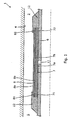
- Fig. 1 shows a cross-sectional view along a longitudinal extension of an annular barrier 1 in its unexpanded condition.
- the annular barrier 1 is rotationally symmetric around a centre axis of rotation.
- the annular barrier is to be expanded in an annulus 2 between a well tubular structure 3 and an inside wall 4 of a borehole 5 downhole.
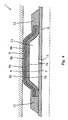
- Fig. 2 shows the annular barrier of Fig. 1 In its expanded condition, providing zone isolation between a first zone and a second zone of the borehole 5.
- the annular barrier 1 comprises a tubular part 6 for mounting as part of the well tubular structure and an expandable metal sleeve 7 surrounding the tubular part 6.
- the expandable metal sleeve has an inner face 7a facing the tubular part, and each end 71, 72 of the expandable metal sleeve is connected with a connection part 12 which is connected with the tubular part, thereby defining a space 13 between the inner face of the expandable metal sleeve 7 and the tubular part.
- the space 13 is defined by the expandable metal sleeve, the connection parts 12 and the tubular part 6.
- the annular barrier further comprises a first safety metal sleeve 8 surrounding the tubular part and abutting the expandable metal sleeve 7.
- the first safety metal sleeve has a first inner face 8a abutting an outer face 7b of the expandable metal sleeve, and each end 81, 82 of the first safety metal sleeve is connected with the connection part 12 which is connected with the tubular part.
- the tubular part 6 comprises an expansion opening 11 for allowing fluid to enter the space 13 during expansion of the annular barrier 1.
- the inner face of the first safety metal sleeve 8 abuts and contacts the face of the expandable metal sleeve along the whole length of the expandable metal sleeve in its unexpanded condition.
- the outer face 8b of the first safety metal sleeve abuts the inner wall of the borehole and during expansion, and the safety metal sleeve. limits the free movement of the expandable metal sleeve. Furthermore, the force applied to the expandable metal sleeve 7 is transferred to the safety metal sleeve 8 by means of the expandable metal sleeve, resulting in a more even distribution of the force applied on the safety metal sleeve than when applied on the expandable metal sleeve.
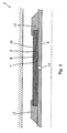
- Fig. 3 shows a cross-sectional view along a longitudinal extension of an annular barrier 1 condition further comprising a second safety metal sleeve 9 surrounding the tubular part, the expandable metal sleeve 7 and the first safety metal sleeve 8.
- the second safety metal sleeve 9 has a second Inner face 9a facing the first safety metal sleeve 8, and each end 91, 92 of the second safety metal sleeve 9 is connected with the connection part 12 which again is connected with the tubular part.
- the tubular part 6 comprises an expansion opening 11 for allowing fluid to enter the space 13 during expansion of the annular barrier 1.
- Fig. 4 shows the annular barrier of Fig. 3 in its expanded condition, providing zone Isolation between a first zone and a second zone of the borehole 5.
- Fig. 5 shows an annular barrier further comprising an additional safety metal sleeve 10.
- the annular barrier 1 shown in Fig. 5 comprises one additional safety metal sleeve 10, the first and second safety metal sleeve 8, 9 and the expandable metal sleeve 7, but even more additional safety metal sleeves may be added to avoid ruptures of the annular barrier.
- the annular barrier may be optimised by using safety metal sleeves with different required expansion pressures, such that peripheral sleeves have lower required expansion pressures than more central sleeves. If the safety metal sleeves have lower required expansion pressures, e.g. because they are thinner than the expandable metal sleeve such as shown in Figs. 1 and 2 , the pressure required to expand the annular barrier may be lowered.
- the sleeves may be made from different materials to provide a difference in required expansion pressure, e.g. one sleeve may be designed to require a smaller expansion pressure than another sleeve by using two different materials.
- the use of different materials may be used to provide a very ductile material in the outermost sleeves to inhibit necking in the outermost sleeves during expansion.
- the innermost sleeves such as the expandable metal sleeve and the first safety metal sleeve, may be be made from a less ductile material, which may resist a larger external pressure from the outside of the annular barrier, e.g. sudden changes in the borehole pressure. Since the outermost sleeves are supported by the innermost sleeves when a pressure is applied from the outside, the ability of the innermost sleeves to resist such pressures is important when requiring an annular barrier with a high collapse pressure.
- the thickness of the expandable metal sleeve shown in Fig. 5 is substantially reduced compared to the expandable metal sleeves shown in Figs. 1-4 .
- the overall strength of the annular barrier is increased, and the thickness of the expandable metal sleeve 7 may be decreased in order to reduce the total thickness of the sleeves.
- An annular barrier may comprise several additional safety metal sleeves 10, such as three additional safety metal sleeves 10, such as four additional safety metal sleeves 10, such as five additional safety metal sleeves 10, or even more additional safety metal sleeves.
- Figs. 6a-6c show a known annular barrier comprising an expandable metal sleeve 7 with no safety metal sleeves.
- the expandable metal sleeve 7 has a weak area 17a, e.g. a thinning, an area with one or more fractures, an area with reduced strength due to material composition, an area with impurities.
- a weak area 17a e.g. a thinning
- the expandable metal sleeve starts to deform more rapidly around the weak area 17a and bulge due to the reduced strength in this weak area, as shown in Fig. 6b .
- the more rapid expansion of the material around the weak area leads to the creation of a "bubble" oh the expandable metal sleeve 7 near the weak area.
- the expandable metal sleeve thins in this area and is more likely to have a fracture 20 near the weak area 17a, leading to at least a local rupture if not a circumferential rupture of the annular barrier as illustrated in Fig. 6c .
- Figs. 7a-7c show an annular barrier comprising an expandable metal sleeve 7 and a first safety metal sleeve 8.
- the expandable metal sleeve 7 has a weak area 17a, which is most likely to occur during the manufacturing process of making the expandable metal sleeve.
- the first safety metal sleeve also has a weak area 17b, it is not likely to be arranged opposite the weak area of the expandable metal sleeve.
- the safety metal sleeve 8 braces and supports the weak area 17a of the expandable metal sleeve such that it cannot bulge and form a bubble, such as the one shown in Fig. 6b .
- the safety metal sleeve prevents the expandable metal sleeve from moving freely but controls the expansion process of the expandable metal sleeve to occur more evenly.
- the force from the expansion fluid in the space 13 will be applied on the inner face 7a of the expandable metal sleeve 7, and since the safety metal sleeve abuts the expandable metal sleeve, the force on the safety metal sleeve will be applied by the expandable metal sleeve directly.
- the safety metal sleeve 8 comprise a weak area 17b
- the part of the expandable metal sleeve close to the weak area will brace the weak area 17b of the safety metal sleeve such that a bubble is not formed on the safety metal sleeve as well.
- the force on the safety metal sleeve is distributed evenly to the safety metal sleeve by means of the expandable metal sleeve, and thus no force will be applied to a part of the safety metal sleeve which is not in contact with the expandable metal sleeve until the expandable metal sleeve is once again in contact with that part of the safety metal sleeve.
- no bulging of the safety metal sleeve can occur as no force will be applied to the somewhat bulging part, resulting in a subsequent burst of the safety metal sleeve.
- the safety metal sleeve of Figs. 7a-7b is thinner than the expandable metal sleeve, e.g. the safety metal sleeve may be 0.5-1.0 mm and the expandable metal sleeve may be 5-10 mm and thus, by adding only a thin outer sleeve, the risk of fracturing the expandable metal sleeve during expansion is substantially reduced without substantially increasing the overall thickness of the annular barrier.
- Figs. 8a-8c show an annular barrier comprising an expandable metal sleeve 7, a first safety metal sleeve 8 and a second safety metal sleeve 9.
- the expandable metal sleeve 7 has a weak area 17a
- the first safety metal sleeve 8 has a weak area 17b
- the second safety metal sleeve 9 has a weak area 17c.
- Increasing the number of safety metal sleeves reduces the risk of all sleeves having a weak area close to each other. If all sleeves have a weak area close to each other, the situation resembles the situation shown in Fig. 6a where only one sleeve comprising a weak area constitutes the expandable part of the annular barrier.
- a safety metal sleeve substantially reduces the risk of rupturing the expandable metal sleeve during expansion, and the addition of more safety metal sleeves even further minimises this risk.
- the two inner sleeves i.e. the expandable metal sleeve and the first safety metal sleeve, are still braced by the second safety metal sleeve to ensure that a "bubble" is not formed.
- annular barrier has a large surface area and the weak areas of the sleeves with modem production techniques are typically very small and widely spread on this large surface area, the risk of two overlapping weak areas is very small.
- adding one more safety metal sleeves as shown in Figs. 8a-8c or even a third safety metal sleeve as shown in Fig. 5 almost eliminates the risk of overlapping weak areas, since the probability may typically be lowered by several orders of magnitude for every additional safety metal sleeve.
- Fig. 9 shows a known barrier 400 comprising an expandable sleeve member 40 surrounding a tubular section 41 and a further outer sleeve member 42 partially surrounding the expandable sleeve member 40 and enclosing a space 43 filled with a sealing material 44 such as a polymeric material.
- a sealing material 44 such as a polymeric material.
- the expandable metal sleeve member comprises a weak area 45
- the expandable metal sleeve member 40 may still rupture during expansion, since a bubble or bulging may start to form within the space 43 and displace the polymeric material and eventually lead to a fracture in the sealing expandable metal sleeve member 40.
- the collapse strength of the expandable metal sleeve member is thus substantially reduced.
- the barrier leaks since the pressurised fluid expanding the expandable metal sleeve member will force its way through the polymeric material and out through the opening, and a seal will never be formed.
- the annular barrier of the present invention may be improved with respect to sealing properties towards the inside wall 4 of the borehole by adding an additional sealing element surrounding an outermost saftey sleeve, which comprises an Intermediate layer of elastomer, rubber or polymer arranged between the outermost safety metal sleeve and a sealing element sleeve.
- an additional sealing element surrounding an outermost saftey sleeve which comprises an Intermediate layer of elastomer, rubber or polymer arranged between the outermost safety metal sleeve and a sealing element sleeve.
- other known sealing elements may be added to the annular barrier surrounding the outermost saftey sleeve to improve sealing properties of the annular barrier.
- the outermost safety metal sleeve may be made from or comprise a sealing metal material. If additional sealing elements surrounding the outermost safety metal sleeve is inappropriate for other reasons such as limited space in the annulus, the outermost safety metal sleeve may be made from a material having good sealing properties such as high ductility.
- the annular barrier may comprise restricting a free expansion of the sleeves.
- the expandable metal sleeve 7 and the additional safety metal sleeves 8, 9, 10 may be made from different materials, one having a higher strength and thereby lower ductility than the other material having a lower strength but higher ductility.
- the annular barrier may comprise the materials adapted to provide high strength or high ductility in a preferred combination. Once expanded, the overall effect is an annular barrier with a higher collapse resistance and higher resistance towards rupture during expansion.
- the metal used for the sleeves may have an elongation of 10-35%, preferably 25-35%.
- the metal may have a yield strength (cold worked) of 500-1000 MPa, preferably 500-700 MPa.
- the sleeves may be a cold-drawn or hot-drawn tubular structure.
- the thickness of the expandable metal sleeve may preferably be at least 10% greater than the thickness of the safety metal sleeves, and more preferably at least 15% greater than the thickness of the safety metal sleeves, and even more preferably at least 20% greater than the thickness of the safety metal sleeves.
- the thickness of the safety metal sleeve may be 0.5 mm to 5 mm, and the thickness of the expandable metal sleeve may be 5 mm to 20 mm.
- the safety metal sleeves may preferably be made from a material having an elongation of more than 10% of an elongation of the material of the expandable metal sleeve.
- the annular barrier may preferably comprise an expandable metal sleeve made from a material having a yield strength which is at least 10% higher than a yield strength of a material of the first and/or second safety metal sleeve, or more preferably at least 15% higher and even more preferably at least 20% higher than a yield strength of the material of the first and/or second safety metal sleeve.
- the expandable metal sleeve may have an unexpanded outside diameter and an expanded outside diameter, the expanded diameter of the expandable metal sleeve being at least 10% larger than the unexpanded diameter, preferably at least 15% larger than the unexpanded diameter, and more preferably at least 30% larger than the unexpanded diameter.
Landscapes
- Geology (AREA)
- Life Sciences & Earth Sciences (AREA)
- Engineering & Computer Science (AREA)
- Mining & Mineral Resources (AREA)
- Environmental & Geological Engineering (AREA)
- Fluid Mechanics (AREA)
- Physics & Mathematics (AREA)
- General Life Sciences & Earth Sciences (AREA)
- Geochemistry & Mineralogy (AREA)
- Filling Or Discharging Of Gas Storage Vessels (AREA)
- Piles And Underground Anchors (AREA)
- Mechanical Operated Clutches (AREA)
- Pipe Accessories (AREA)
- Pressure Vessels And Lids Thereof (AREA)
- Earth Drilling (AREA)
Claims (14)
- Barrière annulaire (1) destinée à être étendue dans un espace annulaire (2) entre une structure tubulaire de puits (3) et une paroi intérieure (4) d'un trou de forage (5) en fond de trou pour fournir une zone d'isolation entre une première zone (200) et une seconde zone (300) du trou de forage, comprenant
une partie tubulaire (6) pour le montage étant une partie de la structure tubulaire de puits,
un manchon métallique extensible (7) entourant la partie tubulaire et comportant une face intérieure (7a) faisant face à la partie tubulaire et une face extérieure (7b) dirigée vers la paroi intérieure du trou de forage, chaque extrémité (71, 72) du manchon métallique extensible étant reliée à une partie de liaison (12) qui est reliée à la partie tubulaire,
un espace (13) entre la face intérieure du manchon métallique extensible et la partie tubulaire, et
une ouverture d'expansion (11) dans la partie tubulaire (6) à travers laquelle du fluide peut entrer dans l'espace (13) afin d'étendre le manchon métallique extensible (7),
dans lequel la barrière annulaire comprend en outre un premier manchon métallique de sécurité (8) entourant la partie tubulaire et venant en butée sur le manchon métallique extensible, caractérisé en ce que
ledit premier manchon métallique de sécurité a une première face (8a) venant en butée sur la face du manchon métallique extensible, chaque extrémité (81, 82) du premier manchon métallique de sécurité étant reliée à la partie de liaison (12) qui est reliée à la partie tubulaire. - Barrière annulaire selon la revendication 1, dans laquelle le premier manchon métallique de sécurité comporte une première face intérieure (8a) venant en butée sur la face extérieure du manchon métallique extensible.
- Barrière annulaire selon la revendication 1 ou 2, comprenant en outre un second manchon métallique de sécurité (9) entourant la partie tubulaire, ledit second manchon métallique de sécurité comportant une seconde face intérieure (9a) faisant face au manchon métallique de sécurité, chaque extrémité (91, 92) du second manchon métallique de sécurité étant reliée à la partie de liaison (12) qui est reliée à la partie tubulaire.
- Barrière annulaire selon la revendication 3, comprenant en outre un troisième manchon métallique de sécurité (10), ledit troisième manchon métallique de sécurité comportant une troisième face intérieure (10a) faisant face à la seconde face extérieure (9b) du second manchon métallique de sécurité, chaque extrémité (101, 102) du troisième manchon métallique de sécurité étant reliée à la partie de liaison (12) qui est reliée à la partie tubulaire.
- Barrière annulaire selon la revendication 1, comprenant en outre une pluralité de manchons métalliques de sécurité supplémentaires entourant la partie tubulaire et le premier manchon métallique de sécurité et étant reliés à la partie de liaison (12) qui est reliée à la partie tubulaire.
- Barrière annulaire selon l'une quelconque des revendications précédentes, dans laquelle le manchon métallique extensible et le(s) manchon(s) métallique(s) de sécurité ont différentes pression(s) d'extension requises.
- Barrière annulaire selon l'une quelconque des revendications précédentes, dans laquelle le manchon métallique extensible et le(s) manchon(s) métallique de sécurité sont faits de matériaux différents.
- Barrière annulaire selon l'une quelconque des revendications précédentes, dans laquelle les manchons ont une épaisseur et l'épaisseur du manchon métallique extensible est supérieure à l'épaisseur du manchon métallique de sécurité.
- Barrière annulaire selon l'une quelconque des revendications précédentes, dans laquelle le manchon métallique de sécurité a une ductilité supérieure à celle du manchon métallique extensible.
- Barrière annulaire selon l'une quelconque des revendications précédentes, dans laquelle le manchon métallique extensible a une limite d'élasticité supérieure à celle du manchon métallique de sécurité.
- Barrière annulaire selon la revendication 9, dans laquelle le premier manchon métallique de sécurité est fait d'un matériau ayant un allongement de plus de 10% d'un allongement du matériau du manchon métallique extensible.
- Barrière annulaire selon l'une quelconque des revendications précédentes, dans laquelle un élément d'étanchéité supplémentaire entourant un manchon de sécurité le plus extérieur comprend une couche intermédiaire d'élastomère, de caoutchouc ou de polymère agencée entre le manchon métallique de sécurité le plus extérieur et un manchon d'élément d'étanchéité.
- Barrière annulaire selon l'une quelconque des revendications 3-5, dans laquelle le manchon métallique de sécurité le plus proche de la paroi intérieure (4) du trou de forage est fait d'un matériau métallique d'étanchéité.
- Barrière annulaire selon l'une quelconque des revendications 3-5, dans laquelle le manchon métallique de sécurité le plus proche de la paroi intérieure (4) du trou de forage comprend au moins un élément d'étanchéité.
Priority Applications (11)
| Application Number | Priority Date | Filing Date | Title |
|---|---|---|---|
| EP11181068.5A EP2570587B1 (fr) | 2011-09-13 | 2011-09-13 | Barrière annulaire dotée d'un manchon métallique de sécurité |
| DK11181068.5T DK2570587T3 (da) | 2011-09-13 | 2011-09-13 | Ringformet barriere med sikkerhedsmetalrørstykke |
| MYPI2014000590A MY174721A (en) | 2011-09-13 | 2012-09-12 | Annular barrier with safety metal sleeve |
| BR112013020172-0A BR112013020172B1 (pt) | 2011-09-13 | 2012-09-12 | barreira anular a ser expandida em um espaço anular entre uma estrutura tubular do poço e uma parede interior de um furo de poço |
| CN201280041856.2A CN103764943A (zh) | 2011-09-13 | 2012-09-12 | 具有安全金属套筒的环形屏障 |
| CN201910537373.5A CN110242246A (zh) | 2011-09-13 | 2012-09-12 | 具有安全金属套筒的环形屏障 |
| PCT/EP2012/067819 WO2013037816A1 (fr) | 2011-09-13 | 2012-09-12 | Barrière annulaire avec manchon de sécurité métallique |
| CA2814336A CA2814336C (fr) | 2011-09-13 | 2012-09-12 | Barriere annulaire avec manchon de securite metallique |
| RU2014111784A RU2630339C2 (ru) | 2011-09-13 | 2012-09-12 | Затрубный барьер с предохранительной металлической муфтой |
| MX2014002348A MX344574B (es) | 2011-09-13 | 2012-09-12 | Barrera anular con manga de metal de seguridad. |
| US13/878,609 US10844686B2 (en) | 2011-09-13 | 2012-09-12 | Annular barrier with safety metal sleeve |
Applications Claiming Priority (1)
| Application Number | Priority Date | Filing Date | Title |
|---|---|---|---|
| EP11181068.5A EP2570587B1 (fr) | 2011-09-13 | 2011-09-13 | Barrière annulaire dotée d'un manchon métallique de sécurité |
Publications (2)
| Publication Number | Publication Date |
|---|---|
| EP2570587A1 EP2570587A1 (fr) | 2013-03-20 |
| EP2570587B1 true EP2570587B1 (fr) | 2013-10-30 |
Family
ID=46826556
Family Applications (1)
| Application Number | Title | Priority Date | Filing Date |
|---|---|---|---|
| EP11181068.5A Revoked EP2570587B1 (fr) | 2011-09-13 | 2011-09-13 | Barrière annulaire dotée d'un manchon métallique de sécurité |
Country Status (10)
| Country | Link |
|---|---|
| US (1) | US10844686B2 (fr) |
| EP (1) | EP2570587B1 (fr) |
| CN (2) | CN103764943A (fr) |
| BR (1) | BR112013020172B1 (fr) |
| CA (1) | CA2814336C (fr) |
| DK (1) | DK2570587T3 (fr) |
| MX (1) | MX344574B (fr) |
| MY (1) | MY174721A (fr) |
| RU (1) | RU2630339C2 (fr) |
| WO (1) | WO2013037816A1 (fr) |
Families Citing this family (20)
| Publication number | Priority date | Publication date | Assignee | Title |
|---|---|---|---|---|
| US9267368B2 (en) * | 2013-04-29 | 2016-02-23 | Baker Hughes Incorporated | Fracturing multiple zones with inflatables |
| FR3012512A1 (fr) | 2013-10-30 | 2015-05-01 | Saltel Ind | Chemise metallique expansible et dispositif qui en fait usage |
| WO2016202834A1 (fr) * | 2015-06-16 | 2016-12-22 | Welltec A/S | Procédé de rhabillage et système de complétion rhabillé |
| CN105587287A (zh) * | 2016-03-07 | 2016-05-18 | 威海丰泰新材料科技股份有限公司 | 一种扩张式封隔器 |
| DK3658744T3 (da) * | 2017-07-27 | 2022-03-07 | Welltec Oilfield Solutions Ag | Ringformet barriere til brønde med små diametre |
| GB2565778B (en) * | 2017-08-21 | 2019-12-04 | Morphpackers Ltd | Improved isolation barrier |
| GB2572449B (en) | 2018-03-30 | 2020-09-16 | Morphpackers Ltd | Improved isolation barrier |
| EP3584403A1 (fr) * | 2018-06-19 | 2019-12-25 | Welltec Oilfield Solutions AG | Barrière annulaire |
| US11802455B2 (en) * | 2019-01-23 | 2023-10-31 | Schlumberger Technology Corporation | Expandable metal packer with anchoring system |
| US11788365B2 (en) | 2019-01-23 | 2023-10-17 | Saltel Industries Sas | Expandable metal packer system with pressure control device |
| US10662734B1 (en) | 2019-09-14 | 2020-05-26 | Vertice Oil Tools | Methods and systems for preventing hydrostatic head within a well |
| US11773681B2 (en) | 2019-09-14 | 2023-10-03 | Vertice Oil Tools Inc. | Methods and systems associated with developing a metal deformable packer |
| TWI739530B (zh) * | 2020-07-27 | 2021-09-11 | 昶城有限公司 | 伸縮管件的密封裝置 |
| EP4015763A1 (fr) * | 2020-12-18 | 2022-06-22 | Welltec Oilfield Solutions AG | Système d'exécution de fond de trou |
| EP4043691A1 (fr) * | 2021-02-12 | 2022-08-17 | Welltec Oilfield Solutions AG | Barrière annulaire et système de fond de trou |
| US11598472B2 (en) * | 2021-04-15 | 2023-03-07 | Halliburton Energy Services, Inc. | Clamp on seal for water leaks |
| DK4323620T3 (da) * | 2021-04-16 | 2025-11-10 | Welltec Mfg Center Completions Aps | Ringformet barriere og brøndsystem |
| CN114689128B (zh) * | 2022-05-31 | 2022-08-19 | 青岛道万科技有限公司 | 一种特种温度压力测量仪及其方法 |
| EP4506535A1 (fr) * | 2023-08-08 | 2025-02-12 | Welltec Manufacturing Center Completions ApS | Système de complétion de fond de trou |
| EP4650563A1 (fr) * | 2024-05-17 | 2025-11-19 | Welltec Manufacturing Center Completions ApS | Composant de complétion |
Citations (1)
| Publication number | Priority date | Publication date | Assignee | Title |
|---|---|---|---|---|
| US20060027371A1 (en) * | 2004-08-04 | 2006-02-09 | Read Well Services Limited | Apparatus and method |
Family Cites Families (22)
| Publication number | Priority date | Publication date | Assignee | Title |
|---|---|---|---|---|
| US2098484A (en) * | 1936-04-21 | 1937-11-09 | Brundred Oil Corp | Packer |
| US4967846A (en) * | 1984-04-04 | 1990-11-06 | Completion Tool Company | Progressively inflated packers |
| US4768590A (en) * | 1986-07-29 | 1988-09-06 | Tam International, Inc. | Inflatable well packer |
| GB9117683D0 (en) * | 1991-08-16 | 1991-10-02 | Head Philip F | Well packer |
| US5507345A (en) | 1994-11-23 | 1996-04-16 | Chevron U.S.A. Inc. | Methods for sub-surface fluid shut-off |
| RU6406U1 (ru) * | 1995-04-19 | 1998-04-16 | Клявин Рим Мусеевич | Пакерующее устройство |
| RU2128279C1 (ru) | 1997-06-16 | 1999-03-27 | Закрытое акционерное общество "ЮКСОН" | Надувной гидравлический пакер |
| FR2791732B1 (fr) * | 1999-03-29 | 2001-08-10 | Cooperation Miniere Et Ind Soc | Dispositif d'obturation d'un puits de forage |
| RU2224872C1 (ru) * | 2002-07-29 | 2004-02-27 | Государственное унитарное предприятие Научно-производственное объединение "Гидротрубопровод" | Пакер |
| GB0227206D0 (en) | 2002-11-21 | 2002-12-24 | Qinetiq Ltd | Electrical transmission system |
| RU2249669C1 (ru) * | 2003-08-14 | 2005-04-10 | Общество с ограниченной ответственностью "ЛУКОЙЛ-ПЕРМЬ" | Двухпакерное устройство |
| US7234533B2 (en) * | 2003-10-03 | 2007-06-26 | Schlumberger Technology Corporation | Well packer having an energized sealing element and associated method |
| CN1624293A (zh) * | 2003-12-04 | 2005-06-08 | 中国石油天然气股份有限公司 | 自然分流平衡挤注堵水工艺 |
| US7347274B2 (en) | 2004-01-27 | 2008-03-25 | Schlumberger Technology Corporation | Annular barrier tool |
| US20060042801A1 (en) | 2004-08-24 | 2006-03-02 | Hackworth Matthew R | Isolation device and method |
| WO2008033115A1 (fr) * | 2006-09-11 | 2008-03-20 | Halliburton Energy Services, Inc. | Construction de garniture d'étanchéité gonflable |
| CN101532600B (zh) | 2008-03-13 | 2013-03-13 | 中国石化集团胜利石油管理局钻井工艺研究院 | 一种实体膨胀管堵漏方法 |
| US20090255691A1 (en) * | 2008-04-10 | 2009-10-15 | Baker Hughes Incorporated | Permanent packer using a slurry inflation medium |
| US8369667B2 (en) * | 2008-05-23 | 2013-02-05 | Halliburton Energy Services, Inc. | Downhole cable |
| ES2464457T3 (es) | 2009-01-12 | 2014-06-02 | Welltec A/S | Barrera anular y sistema de barrera anular |
| EP2312119A1 (fr) | 2009-10-07 | 2011-04-20 | Welltec A/S | Barrière annulaire |
| EP2706188B1 (fr) | 2011-01-25 | 2017-10-11 | Welltec A/S | Barrière annulaire avec diaphragme |
-
2011
- 2011-09-13 EP EP11181068.5A patent/EP2570587B1/fr not_active Revoked
- 2011-09-13 DK DK11181068.5T patent/DK2570587T3/da active
-
2012
- 2012-09-12 US US13/878,609 patent/US10844686B2/en not_active Expired - Fee Related
- 2012-09-12 CN CN201280041856.2A patent/CN103764943A/zh active Pending
- 2012-09-12 CN CN201910537373.5A patent/CN110242246A/zh active Pending
- 2012-09-12 MY MYPI2014000590A patent/MY174721A/en unknown
- 2012-09-12 BR BR112013020172-0A patent/BR112013020172B1/pt not_active IP Right Cessation
- 2012-09-12 CA CA2814336A patent/CA2814336C/fr not_active Expired - Fee Related
- 2012-09-12 RU RU2014111784A patent/RU2630339C2/ru active
- 2012-09-12 WO PCT/EP2012/067819 patent/WO2013037816A1/fr not_active Ceased
- 2012-09-12 MX MX2014002348A patent/MX344574B/es active IP Right Grant
Patent Citations (1)
| Publication number | Priority date | Publication date | Assignee | Title |
|---|---|---|---|---|
| US20060027371A1 (en) * | 2004-08-04 | 2006-02-09 | Read Well Services Limited | Apparatus and method |
Also Published As
| Publication number | Publication date |
|---|---|
| CN103764943A (zh) | 2014-04-30 |
| CA2814336A1 (fr) | 2013-03-21 |
| MX2014002348A (es) | 2014-04-14 |
| US10844686B2 (en) | 2020-11-24 |
| RU2014111784A (ru) | 2015-10-20 |
| EP2570587A1 (fr) | 2013-03-20 |
| BR112013020172A2 (pt) | 2016-11-08 |
| BR112013020172B1 (pt) | 2020-11-03 |
| DK2570587T3 (da) | 2013-11-11 |
| MX344574B (es) | 2016-12-20 |
| WO2013037816A1 (fr) | 2013-03-21 |
| CN110242246A (zh) | 2019-09-17 |
| RU2630339C2 (ru) | 2017-09-07 |
| CA2814336C (fr) | 2014-08-12 |
| US20140196887A1 (en) | 2014-07-17 |
| MY174721A (en) | 2020-05-10 |
Similar Documents
| Publication | Publication Date | Title |
|---|---|---|
| EP2570587B1 (fr) | Barrière annulaire dotée d'un manchon métallique de sécurité | |
| US11473392B2 (en) | Downhole expandable metal tubular | |
| US9359860B2 (en) | Annular barrier | |
| US8997854B2 (en) | Swellable packer anchors | |
| US9217308B2 (en) | Active external casing packer (ECP) for frac operations in oil and gas wells | |
| EP2538018A1 (fr) | Barrière annulaire dotée d'un joint externe | |
| US3542127A (en) | Reinforced inflatable packer with expansible back-up skirts for end portions | |
| US12392212B2 (en) | Annular barrier | |
| EP2312119A1 (fr) | Barrière annulaire | |
| EP2706188B1 (fr) | Barrière annulaire avec diaphragme | |
| EP2418348B1 (fr) | Bagues de remplissage pour emballeuses gonflables | |
| US20140014374A1 (en) | Swellable packer | |
| WO2010135644A2 (fr) | Système de joint d'étanchéité métallique à forte dilatation | |
| US20160348463A1 (en) | Annular barrier having a downhole expandable tubular | |
| US20200165892A1 (en) | Annular barrier | |
| EP2625375B1 (fr) | Barrière annulaire | |
| AU2013100364A4 (en) | Annular barrier with safety metal sleeve | |
| US12326053B2 (en) | Sealing assembly employing a cylindrical protective sleeve | |
| CN121556813A (zh) | 一种尾管顶部封隔器 | |
| AU2013100388B4 (en) | Annular barrier |
Legal Events
| Date | Code | Title | Description |
|---|---|---|---|
| PUAI | Public reference made under article 153(3) epc to a published international application that has entered the european phase |
Free format text: ORIGINAL CODE: 0009012 |
|
| AK | Designated contracting states |
Kind code of ref document: A1 Designated state(s): AL AT BE BG CH CY CZ DE DK EE ES FI FR GB GR HR HU IE IS IT LI LT LU LV MC MK MT NL NO PL PT RO RS SE SI SK SM TR |
|
| AX | Request for extension of the european patent |
Extension state: BA ME |
|
| 17P | Request for examination filed |
Effective date: 20130327 |
|
| 17Q | First examination report despatched |
Effective date: 20130514 |
|
| GRAP | Despatch of communication of intention to grant a patent |
Free format text: ORIGINAL CODE: EPIDOSNIGR1 |
|
| GRAS | Grant fee paid |
Free format text: ORIGINAL CODE: EPIDOSNIGR3 |
|
| INTG | Intention to grant announced |
Effective date: 20130716 |
|
| GRAP | Despatch of communication of intention to grant a patent |
Free format text: ORIGINAL CODE: EPIDOSNIGR1 |
|
| GRAJ | Information related to disapproval of communication of intention to grant by the applicant or resumption of examination proceedings by the epo deleted |
Free format text: ORIGINAL CODE: EPIDOSDIGR1 |
|
| GRAS | Grant fee paid |
Free format text: ORIGINAL CODE: EPIDOSNIGR3 |
|
| INTG | Intention to grant announced |
Effective date: 20130816 |
|
| GRAP | Despatch of communication of intention to grant a patent |
Free format text: ORIGINAL CODE: EPIDOSNIGR1 |
|
| GRAA | (expected) grant |
Free format text: ORIGINAL CODE: 0009210 |
|
| TPAC | Observations filed by third parties |
Free format text: ORIGINAL CODE: EPIDOSNTIPA |
|
| INTG | Intention to grant announced |
Effective date: 20130917 |
|
| AK | Designated contracting states |
Kind code of ref document: B1 Designated state(s): AL AT BE BG CH CY CZ DE DK EE ES FI FR GB GR HR HU IE IS IT LI LT LU LV MC MK MT NL NO PL PT RO RS SE SI SK SM TR |
|
| REG | Reference to a national code |
Ref country code: GB Ref legal event code: FG4D |
|
| REG | Reference to a national code |
Ref country code: CH Ref legal event code: EP |
|
| REG | Reference to a national code |
Ref country code: NL Ref legal event code: T3 |
|
| REG | Reference to a national code |
Ref country code: DK Ref legal event code: T3 Effective date: 20131106 |
|
| REG | Reference to a national code |
Ref country code: AT Ref legal event code: REF Ref document number: 638549 Country of ref document: AT Kind code of ref document: T Effective date: 20131115 |
|
| REG | Reference to a national code |
Ref country code: IE Ref legal event code: FG4D |
|
| REG | Reference to a national code |
Ref country code: NO Ref legal event code: T2 Effective date: 20131030 |
|
| REG | Reference to a national code |
Ref country code: DE Ref legal event code: R096 Ref document number: 602011003548 Country of ref document: DE Effective date: 20131224 |
|
| REG | Reference to a national code |
Ref country code: AT Ref legal event code: MK05 Ref document number: 638549 Country of ref document: AT Kind code of ref document: T Effective date: 20131030 |
|
| REG | Reference to a national code |
Ref country code: LT Ref legal event code: MG4D |
|
| PG25 | Lapsed in a contracting state [announced via postgrant information from national office to epo] |
Ref country code: IS Free format text: LAPSE BECAUSE OF FAILURE TO SUBMIT A TRANSLATION OF THE DESCRIPTION OR TO PAY THE FEE WITHIN THE PRESCRIBED TIME-LIMIT Effective date: 20140228 Ref country code: HR Free format text: LAPSE BECAUSE OF FAILURE TO SUBMIT A TRANSLATION OF THE DESCRIPTION OR TO PAY THE FEE WITHIN THE PRESCRIBED TIME-LIMIT Effective date: 20131030 Ref country code: LT Free format text: LAPSE BECAUSE OF FAILURE TO SUBMIT A TRANSLATION OF THE DESCRIPTION OR TO PAY THE FEE WITHIN THE PRESCRIBED TIME-LIMIT Effective date: 20131030 Ref country code: SE Free format text: LAPSE BECAUSE OF FAILURE TO SUBMIT A TRANSLATION OF THE DESCRIPTION OR TO PAY THE FEE WITHIN THE PRESCRIBED TIME-LIMIT Effective date: 20131030 Ref country code: FI Free format text: LAPSE BECAUSE OF FAILURE TO SUBMIT A TRANSLATION OF THE DESCRIPTION OR TO PAY THE FEE WITHIN THE PRESCRIBED TIME-LIMIT Effective date: 20131030 Ref country code: BE Free format text: LAPSE BECAUSE OF FAILURE TO SUBMIT A TRANSLATION OF THE DESCRIPTION OR TO PAY THE FEE WITHIN THE PRESCRIBED TIME-LIMIT Effective date: 20131030 |
|
| PG25 | Lapsed in a contracting state [announced via postgrant information from national office to epo] |
Ref country code: LV Free format text: LAPSE BECAUSE OF FAILURE TO SUBMIT A TRANSLATION OF THE DESCRIPTION OR TO PAY THE FEE WITHIN THE PRESCRIBED TIME-LIMIT Effective date: 20131030 Ref country code: AT Free format text: LAPSE BECAUSE OF FAILURE TO SUBMIT A TRANSLATION OF THE DESCRIPTION OR TO PAY THE FEE WITHIN THE PRESCRIBED TIME-LIMIT Effective date: 20131030 Ref country code: RS Free format text: LAPSE BECAUSE OF FAILURE TO SUBMIT A TRANSLATION OF THE DESCRIPTION OR TO PAY THE FEE WITHIN THE PRESCRIBED TIME-LIMIT Effective date: 20131030 Ref country code: CY Free format text: LAPSE BECAUSE OF FAILURE TO SUBMIT A TRANSLATION OF THE DESCRIPTION OR TO PAY THE FEE WITHIN THE PRESCRIBED TIME-LIMIT Effective date: 20131030 Ref country code: ES Free format text: LAPSE BECAUSE OF FAILURE TO SUBMIT A TRANSLATION OF THE DESCRIPTION OR TO PAY THE FEE WITHIN THE PRESCRIBED TIME-LIMIT Effective date: 20131030 |
|
| PG25 | Lapsed in a contracting state [announced via postgrant information from national office to epo] |
Ref country code: PT Free format text: LAPSE BECAUSE OF FAILURE TO SUBMIT A TRANSLATION OF THE DESCRIPTION OR TO PAY THE FEE WITHIN THE PRESCRIBED TIME-LIMIT Effective date: 20140228 |
|
| REG | Reference to a national code |
Ref country code: DE Ref legal event code: R026 Ref document number: 602011003548 Country of ref document: DE |
|
| PLBI | Opposition filed |
Free format text: ORIGINAL CODE: 0009260 |
|
| PLAB | Opposition data, opponent's data or that of the opponent's representative modified |
Free format text: ORIGINAL CODE: 0009299OPPO |
|
| PG25 | Lapsed in a contracting state [announced via postgrant information from national office to epo] |
Ref country code: EE Free format text: LAPSE BECAUSE OF FAILURE TO SUBMIT A TRANSLATION OF THE DESCRIPTION OR TO PAY THE FEE WITHIN THE PRESCRIBED TIME-LIMIT Effective date: 20131030 |
|
| 26 | Opposition filed |
Opponent name: SALTEL INDUSTRIES Effective date: 20140710 |
|
| R26 | Opposition filed (corrected) |
Opponent name: SALTEL INDUSTRIES Effective date: 20140710 |
|
| PG25 | Lapsed in a contracting state [announced via postgrant information from national office to epo] |
Ref country code: PL Free format text: LAPSE BECAUSE OF FAILURE TO SUBMIT A TRANSLATION OF THE DESCRIPTION OR TO PAY THE FEE WITHIN THE PRESCRIBED TIME-LIMIT Effective date: 20131030 Ref country code: CZ Free format text: LAPSE BECAUSE OF FAILURE TO SUBMIT A TRANSLATION OF THE DESCRIPTION OR TO PAY THE FEE WITHIN THE PRESCRIBED TIME-LIMIT Effective date: 20131030 Ref country code: SK Free format text: LAPSE BECAUSE OF FAILURE TO SUBMIT A TRANSLATION OF THE DESCRIPTION OR TO PAY THE FEE WITHIN THE PRESCRIBED TIME-LIMIT Effective date: 20131030 Ref country code: IT Free format text: LAPSE BECAUSE OF FAILURE TO SUBMIT A TRANSLATION OF THE DESCRIPTION OR TO PAY THE FEE WITHIN THE PRESCRIBED TIME-LIMIT Effective date: 20131030 Ref country code: RO Free format text: LAPSE BECAUSE OF FAILURE TO SUBMIT A TRANSLATION OF THE DESCRIPTION OR TO PAY THE FEE WITHIN THE PRESCRIBED TIME-LIMIT Effective date: 20131030 |
|
| PLAX | Notice of opposition and request to file observation + time limit sent |
Free format text: ORIGINAL CODE: EPIDOSNOBS2 |
|
| REG | Reference to a national code |
Ref country code: DE Ref legal event code: R026 Ref document number: 602011003548 Country of ref document: DE Effective date: 20140710 |
|
| PLBB | Reply of patent proprietor to notice(s) of opposition received |
Free format text: ORIGINAL CODE: EPIDOSNOBS3 |
|
| PG25 | Lapsed in a contracting state [announced via postgrant information from national office to epo] |
Ref country code: SI Free format text: LAPSE BECAUSE OF FAILURE TO SUBMIT A TRANSLATION OF THE DESCRIPTION OR TO PAY THE FEE WITHIN THE PRESCRIBED TIME-LIMIT Effective date: 20131030 |
|
| PG25 | Lapsed in a contracting state [announced via postgrant information from national office to epo] |
Ref country code: LU Free format text: LAPSE BECAUSE OF FAILURE TO SUBMIT A TRANSLATION OF THE DESCRIPTION OR TO PAY THE FEE WITHIN THE PRESCRIBED TIME-LIMIT Effective date: 20140913 Ref country code: MC Free format text: LAPSE BECAUSE OF FAILURE TO SUBMIT A TRANSLATION OF THE DESCRIPTION OR TO PAY THE FEE WITHIN THE PRESCRIBED TIME-LIMIT Effective date: 20131030 |
|
| REG | Reference to a national code |
Ref country code: CH Ref legal event code: PL |
|
| REG | Reference to a national code |
Ref country code: IE Ref legal event code: MM4A |
|
| PG25 | Lapsed in a contracting state [announced via postgrant information from national office to epo] |
Ref country code: CH Free format text: LAPSE BECAUSE OF NON-PAYMENT OF DUE FEES Effective date: 20140930 Ref country code: LI Free format text: LAPSE BECAUSE OF NON-PAYMENT OF DUE FEES Effective date: 20140930 |
|
| PG25 | Lapsed in a contracting state [announced via postgrant information from national office to epo] |
Ref country code: IE Free format text: LAPSE BECAUSE OF NON-PAYMENT OF DUE FEES Effective date: 20140913 |
|
| PG25 | Lapsed in a contracting state [announced via postgrant information from national office to epo] |
Ref country code: SM Free format text: LAPSE BECAUSE OF FAILURE TO SUBMIT A TRANSLATION OF THE DESCRIPTION OR TO PAY THE FEE WITHIN THE PRESCRIBED TIME-LIMIT Effective date: 20131030 |
|
| PG25 | Lapsed in a contracting state [announced via postgrant information from national office to epo] |
Ref country code: MT Free format text: LAPSE BECAUSE OF FAILURE TO SUBMIT A TRANSLATION OF THE DESCRIPTION OR TO PAY THE FEE WITHIN THE PRESCRIBED TIME-LIMIT Effective date: 20131030 Ref country code: BG Free format text: LAPSE BECAUSE OF FAILURE TO SUBMIT A TRANSLATION OF THE DESCRIPTION OR TO PAY THE FEE WITHIN THE PRESCRIBED TIME-LIMIT Effective date: 20131030 Ref country code: GR Free format text: LAPSE BECAUSE OF FAILURE TO SUBMIT A TRANSLATION OF THE DESCRIPTION OR TO PAY THE FEE WITHIN THE PRESCRIBED TIME-LIMIT Effective date: 20140131 |
|
| PG25 | Lapsed in a contracting state [announced via postgrant information from national office to epo] |
Ref country code: HU Free format text: LAPSE BECAUSE OF FAILURE TO SUBMIT A TRANSLATION OF THE DESCRIPTION OR TO PAY THE FEE WITHIN THE PRESCRIBED TIME-LIMIT; INVALID AB INITIO Effective date: 20110913 Ref country code: TR Free format text: LAPSE BECAUSE OF FAILURE TO SUBMIT A TRANSLATION OF THE DESCRIPTION OR TO PAY THE FEE WITHIN THE PRESCRIBED TIME-LIMIT Effective date: 20131030 |
|
| REG | Reference to a national code |
Ref country code: FR Ref legal event code: PLFP Year of fee payment: 6 |
|
| APAH | Appeal reference modified |
Free format text: ORIGINAL CODE: EPIDOSCREFNO |
|
| APBM | Appeal reference recorded |
Free format text: ORIGINAL CODE: EPIDOSNREFNO |
|
| APBP | Date of receipt of notice of appeal recorded |
Free format text: ORIGINAL CODE: EPIDOSNNOA2O |
|
| REG | Reference to a national code |
Ref country code: FR Ref legal event code: PLFP Year of fee payment: 7 |
|
| APBQ | Date of receipt of statement of grounds of appeal recorded |
Free format text: ORIGINAL CODE: EPIDOSNNOA3O |
|
| PG25 | Lapsed in a contracting state [announced via postgrant information from national office to epo] |
Ref country code: MK Free format text: LAPSE BECAUSE OF FAILURE TO SUBMIT A TRANSLATION OF THE DESCRIPTION OR TO PAY THE FEE WITHIN THE PRESCRIBED TIME-LIMIT Effective date: 20131030 |
|
| REG | Reference to a national code |
Ref country code: FR Ref legal event code: PLFP Year of fee payment: 8 |
|
| PG25 | Lapsed in a contracting state [announced via postgrant information from national office to epo] |
Ref country code: AL Free format text: LAPSE BECAUSE OF FAILURE TO SUBMIT A TRANSLATION OF THE DESCRIPTION OR TO PAY THE FEE WITHIN THE PRESCRIBED TIME-LIMIT Effective date: 20131030 |
|
| RAP2 | Party data changed (patent owner data changed or rights of a patent transferred) |
Owner name: WELLTEC OILFIELD SOLUTIONS AG |
|
| REG | Reference to a national code |
Ref country code: DE Ref legal event code: R082 Ref document number: 602011003548 Country of ref document: DE Representative=s name: SAMSON & PARTNER PATENTANWAELTE MBB, DE Ref country code: DE Ref legal event code: R081 Ref document number: 602011003548 Country of ref document: DE Owner name: WELLTEC OILFIELD SOLUTIONS AG, CH Free format text: FORMER OWNER: WELLTEC A/S, ALLEROED, DK |
|
| REG | Reference to a national code |
Ref country code: NO Ref legal event code: CHAD Owner name: WELLTEC OILFIELD SOLUTIONS AG, CH Ref country code: NO Ref legal event code: CREP Representative=s name: ACAPO AS, POSTBOKS 1880 NORDNES, 5817 BERGEN |
|
| REG | Reference to a national code |
Ref country code: GB Ref legal event code: 732E Free format text: REGISTERED BETWEEN 20190429 AND 20190502 |
|
| REG | Reference to a national code |
Ref country code: NL Ref legal event code: PD Owner name: WELLTEC OILFIELD SOLUTIONS AG; CH Free format text: DETAILS ASSIGNMENT: CHANGE OF OWNER(S), ASSIGNMENT; FORMER OWNER NAME: WELLTEC A/S Effective date: 20190607 |
|
| RAP2 | Party data changed (patent owner data changed or rights of a patent transferred) |
Owner name: WELLTEC OILFIELD SOLUTIONS AG |
|
| APBY | Invitation to file observations in appeal sent |
Free format text: ORIGINAL CODE: EPIDOSNOBA2O |
|
| APBU | Appeal procedure closed |
Free format text: ORIGINAL CODE: EPIDOSNNOA9O |
|
| APCA | Receipt of observations in appeal recorded |
Free format text: ORIGINAL CODE: EPIDOSNOBA4O |
|
| PGFP | Annual fee paid to national office [announced via postgrant information from national office to epo] |
Ref country code: FR Payment date: 20200918 Year of fee payment: 10 Ref country code: NO Payment date: 20200923 Year of fee payment: 10 Ref country code: DK Payment date: 20200916 Year of fee payment: 10 Ref country code: GB Payment date: 20200921 Year of fee payment: 10 Ref country code: NL Payment date: 20200921 Year of fee payment: 10 Ref country code: DE Payment date: 20200922 Year of fee payment: 10 |
|
| RDAF | Communication despatched that patent is revoked |
Free format text: ORIGINAL CODE: EPIDOSNREV1 |
|
| STAA | Information on the status of an ep patent application or granted ep patent |
Free format text: STATUS: THE PATENT HAS BEEN GRANTED |
|
| REG | Reference to a national code |
Ref country code: DE Ref legal event code: R103 Ref document number: 602011003548 Country of ref document: DE Ref country code: DE Ref legal event code: R064 Ref document number: 602011003548 Country of ref document: DE |
|
| RDAG | Patent revoked |
Free format text: ORIGINAL CODE: 0009271 |
|
| STAA | Information on the status of an ep patent application or granted ep patent |
Free format text: STATUS: PATENT REVOKED |
|
| REG | Reference to a national code |
Ref country code: FI Ref legal event code: MGE |
|
| 27W | Patent revoked |
Effective date: 20210722 |
|
| GBPR | Gb: patent revoked under art. 102 of the ep convention designating the uk as contracting state |
Effective date: 20210722 |