EP4506535A1 - Système de complétion de fond de trou - Google Patents
Système de complétion de fond de trou Download PDFInfo
- Publication number
- EP4506535A1 EP4506535A1 EP23190430.1A EP23190430A EP4506535A1 EP 4506535 A1 EP4506535 A1 EP 4506535A1 EP 23190430 A EP23190430 A EP 23190430A EP 4506535 A1 EP4506535 A1 EP 4506535A1
- Authority
- EP
- European Patent Office
- Prior art keywords
- barrier
- tubular metal
- metal structure
- completion system
- downhole completion
- Prior art date
- Legal status (The legal status is an assumption and is not a legal conclusion. Google has not performed a legal analysis and makes no representation as to the accuracy of the status listed.)
- Withdrawn
Links
Images


Classifications
-
- E—FIXED CONSTRUCTIONS
- E21—EARTH OR ROCK DRILLING; MINING
- E21B—EARTH OR ROCK DRILLING; OBTAINING OIL, GAS, WATER, SOLUBLE OR MELTABLE MATERIALS OR A SLURRY OF MINERALS FROM WELLS
- E21B33/00—Sealing or packing boreholes or wells
- E21B33/10—Sealing or packing boreholes or wells in the borehole
- E21B33/12—Packers; Plugs
- E21B33/1208—Packers; Plugs characterised by the construction of the sealing or packing means
-
- E—FIXED CONSTRUCTIONS
- E21—EARTH OR ROCK DRILLING; MINING
- E21B—EARTH OR ROCK DRILLING; OBTAINING OIL, GAS, WATER, SOLUBLE OR MELTABLE MATERIALS OR A SLURRY OF MINERALS FROM WELLS
- E21B33/00—Sealing or packing boreholes or wells
- E21B33/10—Sealing or packing boreholes or wells in the borehole
- E21B33/13—Methods or devices for cementing, for plugging holes, crevices or the like
- E21B33/134—Bridging plugs
Definitions
- the present invention relates to a downhole completion system for providing plug and abandonment of a well having a top.
- the invention also relates to a downhole completion method for providing plug and abandonment of a downhole completion system.
- Plug and abandonment is an important part of the lifetime of a well. It is also a costly process since the authorities have high requirements for the plugging operations in order to ensure that the well does not pollute the environment.
- the well has parts where the casing or production tubing is surrounded by an annulus which has not been filled with cement during completion.
- Such cased wells may also have an annular space between the intermediate casing and the production casing in the upper part of the well.
- the plug and abandonment becomes complicated since when the casing is filled up with cement to plug the well, the cement cannot completely fill the annular space or the annulus, and there is a risk of a blowout through that annulus or annular space.
- a large rig is shipped to the well to pull the production casing out of the well. Such operation is thus, in the known solution, necessary and expensive.
- the tubing can be removed by pyrotechnics or explosives, but this implies a risk to the remaining part of the completion that other barriers will be damaged and thus a too high risk that the plug and abandonment will leak.
- a downhole completion system for providing plug and abandonment of a well having a top comprising:
- the barrier functions as a conventional barrier during the production time of the well, and when needing to plug a part, if not all, of the well, the obstruction part is heated above a predetermined temperature so that the bypass channel is opened for fluid communication between the top face and the bottom face of the barrier, allowing the melted metal from the melted part of the first well tubular metal structure can flow down the well through the bypass channel. In that way, it is avoided that the heat is accumulated above the barrier, and the risk that such heat would damage other parts of the completion unintentionally is eliminated.
- the barrier is pressure-tight during deployment and normal operations, but when heat is applied above the melting point of the obstruction part, the barrier melts, enabling a bypass between the top and the bottom part of the assembly.
- the obstruction part is removable when heated above a predetermined temperature.
- the predetermined temperature may be above at least 600 °C, preferably above at least 1000 °C.
- the obstruction part may be meltable above at least 600 °C, preferably above at least 1000 °C.
- the temperature-activated bypass assembly may comprise a plurality of bypass channels.
- each bypass channel may comprise an obstruction part.
- the obstruction part may be meltable above at least 600 °C, preferably above at least 1000 °C.
- the obstruction part may be arranged in the bypass channel or on top of the bypass channel.
- the obstruction part may be a meltable, moldable or fusible obstruction part.
- the obstruction part may be an internal obstruction part or a part of the bypass channel.
- the barrier may be a plug arranged inside the first well tubular metal structure so that the first and second volumes are arranged inside the first well tubular metal structure.
- the barrier may be an annular barrier arranged around the first well tubular metal structure between the first well tubular metal structure and a second well tubular metal structure or the borehole so that the first and second volumes are annular volumes.
- the annular barrier may be a production packer.
- the barrier may be a first barrier
- the downhole completion system may further comprise a second barrier, the first barrier being arranged to surround the first well tubular metal structure, and the second barrier being arranged inside the first well tubular metal structure.
- the second barrier may be a plug arranged inside the first well tubular metal structure, isolating a third volume above the plug from a fourth volume inside the first well tubular metal structure.
- the second barrier may comprise a temperature-activated bypass assembly comprising a bypass channel and an obstruction part, the bypass channel extending from the top face to the bottom face for providing fluid communication in the bypass channel when the obstruction part is removed by being heated.
- the barrier may comprise bismuth material.
- the downhole completion system may further comprise a thermite composition arranged inside the first well tubular metal structure above the barrier.
- the downhole completion system may further comprise an ignitor for igniting the thermite composition.
- the downhole completion system may further comprise cement arranged on top of the first barrier and/or the second barrier after igniting the thermite composition and melting part of the first well tubular metal structure.
- the annular barrier may comprise a tubular metal part for mounting as part of the first well tubular metal structure, the tubular metal part having an outer face, comprising:
- one of the ends of the expandable metal sleeve may be connected with the tubular metal part by means of a connection part, and the bypass channel may extend through the connection part, providing fluid communication across the annular barrier.
- tubular metal part may have an axial extension along the axial extension of the first well tubular metal structure.
- tubular metal part may have an inside being pressurised for expanding the expandable metal sleeve.
- bypass channel may extend between the expandable metal sleeve and the tubular metal part for providing fluid communication past the annular barrier when the obstruction part is removed by being heated.
- the invention also relates to a downhole completion method for providing plug and abandonment of a downhole completion system according to any of the proceeding claims, comprising:
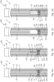
- Fig. 1a shows a downhole completion system 100 for providing plug and abandonment of a well 2 having a top 50.
- the downhole completion system 100 comprises a first well tubular metal structure 1 arranged in a borehole 3, and a barrier 4 is arranged inside the first well tubular metal structure 1, isolating a first volume 101 from a second volume 102.
- the barrier 4 has a top face 5 facing the first volume 101 and a bottom face 6 facing the second volume 102.
- the barrier 4 has a temperature-activated bypass assembly 7 comprising a bypass channel 8 and an obstruction part 9.
- the bypass channel 8 is shown, even though it extends inside the barrier 4, for illustrative purpose only.
- the bypass channel 8 extends from the top face 5 to the bottom face 6 for providing fluid communication between the first volume 101 and the second volume 102 when the obstruction part 9 is removed by being heated.
- the barrier 4 is a plug 4a arranged inside the first well tubular metal structure 1 so that the first and second volumes 101, 102 are arranged inside the first well tubular metal structure 1.
- the first well tubular metal structure 1 is arranged at least partly inside a second well tubular metal structure 1b, and a conventional production packer is arranged between the first and second well tubular metal structures 1, 1b, creating an annular space therebetween.
- the second well tubular metal structure 1b is arranged in the borehole 3, and cement 27 is arranged therebetween.
- the obstruction part 9 of the temperature-activated bypass assembly 7 is melted and flows down the bypass channel 8, creating fluid communication inside the bypass channel 8 from the top face 5 to the bottom face 6.
- the obstruction part 9 may also evaporate.
- the obstruction part 9 is meltable above at least 600 °C, preferably above at least 1000 °C.
- a thermite composition 11 is arranged inside the first well tubular metal structure 1 above the barrier 4 as shown in Fig. 1b , and an ignitor 12 for igniting the thermite composition 11 is activated.
- thermite composition 11 undergoes an exothermic reduction-oxidation (redox) reaction, heat is generated, melting a part 30 of the first well tubular metal structure 1 as shown in Fig. 1c and melting the obstruction part 9, providing fluid communication through the bypass channel 8.
- redox exothermic reduction-oxidation
- the cement 27 can be introduced in the area above the barrier 4 where the part 30 has been removed, as shown in Fig. 1d , and the well 2 is sufficiently plugged.
- the removed part 30 of the first well tubular metal structure 1 may be more than 100 metres, preferably more than 200 metres, and the cement plug 27 provided on top of the barrier 4 as shown in Fig. 1d can be of equal length.
- the obstruction part 9 is an internal obstruction part arranged in a top part of the bypass channel 8, but may also be arranged on top of the bypass channel 8.
- the obstruction part 9 is a meltable, moldable or fusible obstruction part.
- the obstruction part 9 may also be a part of the bypass channel 8 so that the bypass channel 8 and the obstruction part 9 are made as one monolithic whole.
- the bypass channel 8 may be made as a tube of a temperature-resistant material such as ceramic or a similar material withstanding temperatures above 1300 °C.
- the bypass channel 8 may be made as a tube of the same material as the obstruction part 9 and melting along with the obstruction part 9.
- Fig. 2a shows another downhole completion system 100 where the barrier 4 is arranged around the first well tubular metal structure 1, isolating the first volume 101 from the second volume 102, and where the bypass channel 8 extends from the top face 5 to the bottom face 6 for providing fluid communication between the first volume 101 and the second volume 102 when the obstruction part 9 is removed by being heated.
- the bypass channel 8 is shown, even though it extends inside the barrier 4, for illustrative purposes only.
- the barrier 4 is thus an annular barrier 4b arranged around the first well tubular metal structure 1 between the first well tubular metal structure 1 and the second well tubular metal structure 1b or the borehole 3 so that the first and second volumes 101, 102 are annular volumes.
- the annular barrier 4b may thus function as a production packer until the bypass channel 8 is used.
- the barrier 4 is a first barrier 4, and the downhole completion system 100 further comprises a second barrier 10, where the first barrier 4 is arranged to surround the first well tubular metal structure 1, and the second barrier 10 is arranged inside the first well tubular metal structure 1.
- the second barrier 10 is thus a plug 10a arranged inside the first well tubular metal structure 1, isolating a third volume 103 above the plug 10a from a fourth volume 104 below the plug inside the first well tubular metal structure 1.
- the second barrier 10 also comprises a temperature-activated bypass assembly 7b comprising a bypass channel 8b and the obstruction part 9b, where the bypass channel 8b extends from the top face 5 of the second barrier 10 to the bottom face 6 of the second barrier 10 for providing fluid communication in the bypass channel 8b of the second barrier 10 when the obstruction part 9b is removed by being heated, e.g. during the exothermic reaction or in a prior heating operation.
- the temperature-activated bypass assembly 7b of barriers comprises a plurality of bypass channels 8b, and each bypass channel 8b comprises an obstruction part.
- the thermite composition 11 is arranged inside the first well tubular metal structure 1 above the second barrier 10, and then the obstruction part 9b is removed by being heated, e.g. during the exothermic reaction or in a prior heating operation.
- the part 30 of the first well tubular metal structure 1 is melted and flows through the bypass channels 8, 8b in both the first and second barriers 4, 10 as illustrated.
- the downhole completion system 100 further comprises the cement 27 arranged on top of the first and second barriers 4, 10 after igniting the thermite composition and melting part of the first well tubular metal structure 1.
- the barrier 4, 10 may comprise bismuth material or alloy, so when heated the barrier 4, 10 decreases in volume for as long as the melted metal 26 passes the bypass channels 8, 8b, and after some time, the barrier 4, 10 is cooled down again, the bismuth material or alloy expands in volume, closing the bypass channel 8, 8b and increasing the barrier 4, 10 and the P&A (Plug and Abandonment) even further.
- the downhole completion system comprises a barrier 4 having the temperature-activated bypass assembly 7 comprising a bypass channel 8 and the obstruction part 9, where the bypass channel 8 extends from the top face 5 to the bottom face 6 for providing fluid communication between the first volume 101 and the second volume 102 when the obstruction part 9 is removed by being heated.
- the downhole completion system 100 further comprises a plug 10a, being a conventional plug, arranged inside the first well tubular metal structure 1, isolating a third volume 103 above the plug 10a from a fourth volume 104 below the plug 10a inside the first well tubular metal structure 1.
- the part 30 of the first well tubular metal structure 1 melts, and the melted metal 26 flows radially outwards towards the barrier 4, 10, i.e. the annular barrier 4b, down the bypass channels 8 therein, and away from the first volume to the second volume 102.
- the barrier in the form of a plug is illustrated in Fig. 4 , where part of the plug is shown in a cross-sectional view in order to show the bypass channel 8 and the obstruction part 9 therein.
- the annular barrier 4b comprises the tubular metal part 16 for mounting as part of the first well tubular metal structure 1 having a longitudinal extension 24.
- the tubular metal part 16 has an outer face 17, and the annular barrier 4b further comprises the expandable metal sleeve 18 surrounding the tubular metal part 16 and having an outer face 19 facing towards the inner face of the borehole 3 or the second well tubular metal structure 1b and an inner face 20 facing the outer face of the tubular metal part 16.
- Each end 31, 32 of the expandable metal sleeve 18 is connected with the tubular metal part 16, and an annular space 21 is created between the expandable metal sleeve 18 and the tubular metal part 16.
- the tubular metal part 16 has an expansion opening 22 through which fluid may enter the annular space 21 in order to expand the expandable metal sleeve 18. At least one of the ends 31, 32 of the expandable metal sleeve 18 is connected with the tubular metal part 16 by means of a connection part 41, 42, and the bypass channel 8 extends through the connection part 41, 42 and through the annular space 21 between the expandable metal sleeve 18 and the tubular metal part 16, providing fluid communication across the annular barrier 4b when the obstruction part 9 is removed by being heated.
- the tubular metal part 16 has an axial extension 23 along the axial extension 24 of the first well tubular metal structure 1.
- the tubular metal part 16 has an inside 25 being pressurised for expanding the expandable metal sleeve 18.
- fluid or "well fluid” is meant any kind of fluid that may be present in oil or gas wells downhole, such as natural gas, oil, oil mud, crude oil, water, etc.
- gas is meant any kind of gas composition present in a well, completion or open hole, and by “oil” is meant any kind of oil composition, such as crude oil, an oil-containing fluid, etc.
- Oil and water fluids may thus all comprise other elements or substances than gas, oil and/or water, respectively.
- casing or “well tubular metal structure” is meant any kind of pipe, tubing, tubular, liner, string, etc., used downhole in relation to oil or natural gas production.
Landscapes
- Life Sciences & Earth Sciences (AREA)
- Engineering & Computer Science (AREA)
- Geology (AREA)
- Mining & Mineral Resources (AREA)
- Physics & Mathematics (AREA)
- Environmental & Geological Engineering (AREA)
- Fluid Mechanics (AREA)
- General Life Sciences & Earth Sciences (AREA)
- Geochemistry & Mineralogy (AREA)
- Earth Drilling (AREA)
- Pipe Accessories (AREA)
Priority Applications (5)
| Application Number | Priority Date | Filing Date | Title |
|---|---|---|---|
| EP23190430.1A EP4506535A1 (fr) | 2023-08-08 | 2023-08-08 | Système de complétion de fond de trou |
| PCT/EP2024/072378 WO2025032146A1 (fr) | 2023-08-08 | 2024-08-07 | Système de fond de trou |
| CN202480049012.5A CN121569090A (zh) | 2023-08-08 | 2024-08-07 | 井下系统 |
| US18/797,268 US20250052129A1 (en) | 2023-08-08 | 2024-08-07 | Downhole completion system |
| AU2024321233A AU2024321233A1 (en) | 2023-08-08 | 2024-08-07 | Downhole system |
Applications Claiming Priority (1)
| Application Number | Priority Date | Filing Date | Title |
|---|---|---|---|
| EP23190430.1A EP4506535A1 (fr) | 2023-08-08 | 2023-08-08 | Système de complétion de fond de trou |
Publications (1)
| Publication Number | Publication Date |
|---|---|
| EP4506535A1 true EP4506535A1 (fr) | 2025-02-12 |
Family
ID=87567501
Family Applications (1)
| Application Number | Title | Priority Date | Filing Date |
|---|---|---|---|
| EP23190430.1A Withdrawn EP4506535A1 (fr) | 2023-08-08 | 2023-08-08 | Système de complétion de fond de trou |
Country Status (5)
| Country | Link |
|---|---|
| US (1) | US20250052129A1 (fr) |
| EP (1) | EP4506535A1 (fr) |
| CN (1) | CN121569090A (fr) |
| AU (1) | AU2024321233A1 (fr) |
| WO (1) | WO2025032146A1 (fr) |
Families Citing this family (1)
| Publication number | Priority date | Publication date | Assignee | Title |
|---|---|---|---|---|
| US12540527B1 (en) * | 2025-01-28 | 2026-02-03 | Saudi Arabian Oil Company | Methods for sealing leaks in oil and gas wells |
Citations (3)
| Publication number | Priority date | Publication date | Assignee | Title |
|---|---|---|---|---|
| US20070199693A1 (en) * | 2006-02-17 | 2007-08-30 | Innicor Subsurface Technologies Inc | Eutectic material-based seal element for packers |
| WO2018215786A1 (fr) * | 2017-05-24 | 2018-11-29 | Bisn Tec Ltd | Ensemble de déploiement d'outil de fond de trou à séparation améliorée du dispositif de chauffage et procédés d'utilisation de celui-ci |
| US11536111B2 (en) * | 2016-05-24 | 2022-12-27 | BiSN Tec. Ltd. | Downhole tool deployment assembly with improved heater removability and methods of employing such |
Family Cites Families (5)
| Publication number | Priority date | Publication date | Assignee | Title |
|---|---|---|---|---|
| US7775286B2 (en) * | 2008-08-06 | 2010-08-17 | Baker Hughes Incorporated | Convertible downhole devices and method of performing downhole operations using convertible downhole devices |
| EP2570587B1 (fr) * | 2011-09-13 | 2013-10-30 | Welltec A/S | Barrière annulaire dotée d'un manchon métallique de sécurité |
| GB2591687B (en) * | 2016-08-10 | 2021-10-27 | Halliburton Energy Services Inc | Soluble plug usable downhole |
| US11377925B2 (en) * | 2017-10-30 | 2022-07-05 | Conocophillips Company | Through tubing P and A with bismuth alloys |
| US12209478B2 (en) * | 2022-06-08 | 2025-01-28 | Halliburton Energy Services, Inc. | Plug and abandon with fusible alloy seal |
-
2023
- 2023-08-08 EP EP23190430.1A patent/EP4506535A1/fr not_active Withdrawn
-
2024
- 2024-08-07 CN CN202480049012.5A patent/CN121569090A/zh active Pending
- 2024-08-07 US US18/797,268 patent/US20250052129A1/en active Pending
- 2024-08-07 WO PCT/EP2024/072378 patent/WO2025032146A1/fr active Pending
- 2024-08-07 AU AU2024321233A patent/AU2024321233A1/en active Pending
Patent Citations (3)
| Publication number | Priority date | Publication date | Assignee | Title |
|---|---|---|---|---|
| US20070199693A1 (en) * | 2006-02-17 | 2007-08-30 | Innicor Subsurface Technologies Inc | Eutectic material-based seal element for packers |
| US11536111B2 (en) * | 2016-05-24 | 2022-12-27 | BiSN Tec. Ltd. | Downhole tool deployment assembly with improved heater removability and methods of employing such |
| WO2018215786A1 (fr) * | 2017-05-24 | 2018-11-29 | Bisn Tec Ltd | Ensemble de déploiement d'outil de fond de trou à séparation améliorée du dispositif de chauffage et procédés d'utilisation de celui-ci |
Also Published As
| Publication number | Publication date |
|---|---|
| CN121569090A (zh) | 2026-02-24 |
| AU2024321233A1 (en) | 2026-03-12 |
| WO2025032146A1 (fr) | 2025-02-13 |
| US20250052129A1 (en) | 2025-02-13 |
Similar Documents
| Publication | Publication Date | Title |
|---|---|---|
| US12010970B2 (en) | Nano-thermite well plug | |
| US11525329B2 (en) | Apparatus for use in well abandonment | |
| US20220290526A1 (en) | Through tubing p&a with bismuth alloys | |
| US20240060385A1 (en) | An expandable eutectic alloy based downhole tool and methods of deploying such | |
| US12129735B2 (en) | Tool for metal plugging or sealing of casing | |
| US10072477B2 (en) | Methods of deployment for eutectic isolation tools to ensure wellbore plugs | |
| EP3571373B1 (fr) | Outil d'installation compact | |
| EP3578749B1 (fr) | Outils de chevauchement de fond de trou | |
| US6237688B1 (en) | Pre-drilled casing apparatus and associated methods for completing a subterranean well | |
| US7455104B2 (en) | Expandable elements | |
| US6494261B1 (en) | Apparatus and methods for perforating a subterranean formation | |
| EA021471B1 (ru) | Гидравлический разрыв пласта с использованием телескопического элемента и герметизацией кольцевого пространства | |
| SG189917A1 (en) | Method and apparatus for creating an annular barrier in a subterranean wellbore | |
| WO2014108431A2 (fr) | Procédé pour boucher un puits à hydrocarbures | |
| US5957205A (en) | Sand exclusion liner and method of using the same | |
| US20250052129A1 (en) | Downhole completion system | |
| WO2022171604A1 (fr) | Procédé d'abandon d'un puits de forage achevé | |
| EP3631150B1 (fr) | Ensemble de déploiement d'outil de fond de trou à séparation améliorée du dispositif de chauffage et procédés d'utilisation de celui-ci | |
| US11885191B2 (en) | Patch for joining downhole ends of pipes | |
| US20230265745A1 (en) | Sand screen assemblies for a subterranean wellbore | |
| WO2024112920A1 (fr) | Procédé de scellement d'un puits ayant de multiples espaces annulaires | |
| NO347280B1 (en) | Downhole millable permanent plug |
Legal Events
| Date | Code | Title | Description |
|---|---|---|---|
| PUAI | Public reference made under article 153(3) epc to a published international application that has entered the european phase |
Free format text: ORIGINAL CODE: 0009012 |
|
| STAA | Information on the status of an ep patent application or granted ep patent |
Free format text: STATUS: THE APPLICATION HAS BEEN PUBLISHED |
|
| AK | Designated contracting states |
Kind code of ref document: A1 Designated state(s): AL AT BE BG CH CY CZ DE DK EE ES FI FR GB GR HR HU IE IS IT LI LT LU LV MC ME MK MT NL NO PL PT RO RS SE SI SK SM TR |
|
| STAA | Information on the status of an ep patent application or granted ep patent |
Free format text: STATUS: THE APPLICATION IS DEEMED TO BE WITHDRAWN |
|
| 18D | Application deemed to be withdrawn |
Effective date: 20250813 |