EP2570594A2 - Aube de turbine avec profil métallique et couvercle d'extrémité céramique et moteur à turbine à gaz associé - Google Patents
Aube de turbine avec profil métallique et couvercle d'extrémité céramique et moteur à turbine à gaz associé Download PDFInfo
- Publication number
- EP2570594A2 EP2570594A2 EP12169739A EP12169739A EP2570594A2 EP 2570594 A2 EP2570594 A2 EP 2570594A2 EP 12169739 A EP12169739 A EP 12169739A EP 12169739 A EP12169739 A EP 12169739A EP 2570594 A2 EP2570594 A2 EP 2570594A2
- Authority
- EP
- European Patent Office
- Prior art keywords
- side wall
- tip cap
- airfoil
- turbine
- suction side
- Prior art date
- Legal status (The legal status is an assumption and is not a legal conclusion. Google has not performed a legal analysis and makes no representation as to the accuracy of the status listed.)
- Withdrawn
Links
- 239000000919 ceramic Substances 0.000 title claims description 4
- 239000000463 material Substances 0.000 claims abstract description 27
- 239000011153 ceramic matrix composite Substances 0.000 claims abstract description 24
- 239000007769 metal material Substances 0.000 claims abstract description 7
- 238000001816 cooling Methods 0.000 claims description 19
- 230000000717 retained effect Effects 0.000 claims description 9
- 239000000835 fiber Substances 0.000 claims description 8
- 239000011159 matrix material Substances 0.000 claims description 4
- 239000011226 reinforced ceramic Substances 0.000 claims 2
- 239000007789 gas Substances 0.000 description 31
- 238000000034 method Methods 0.000 description 9
- 239000002184 metal Substances 0.000 description 7
- 229910052751 metal Inorganic materials 0.000 description 7
- 238000002485 combustion reaction Methods 0.000 description 5
- 239000000428 dust Substances 0.000 description 5
- 238000007789 sealing Methods 0.000 description 4
- XLYOFNOQVPJJNP-UHFFFAOYSA-N water Substances O XLYOFNOQVPJJNP-UHFFFAOYSA-N 0.000 description 4
- 238000004519 manufacturing process Methods 0.000 description 3
- 230000007246 mechanism Effects 0.000 description 3
- 229910000601 superalloy Inorganic materials 0.000 description 3
- PXHVJJICTQNCMI-UHFFFAOYSA-N Nickel Chemical compound [Ni] PXHVJJICTQNCMI-UHFFFAOYSA-N 0.000 description 2
- 230000009286 beneficial effect Effects 0.000 description 2
- 239000002826 coolant Substances 0.000 description 2
- 238000010586 diagram Methods 0.000 description 2
- 239000012530 fluid Substances 0.000 description 2
- 239000000446 fuel Substances 0.000 description 2
- 230000006870 function Effects 0.000 description 2
- 238000001764 infiltration Methods 0.000 description 2
- 230000008595 infiltration Effects 0.000 description 2
- 230000004048 modification Effects 0.000 description 2
- 238000012986 modification Methods 0.000 description 2
- 229920000049 Carbon (fiber) Polymers 0.000 description 1
- 229910000990 Ni alloy Inorganic materials 0.000 description 1
- 229910000831 Steel Inorganic materials 0.000 description 1
- QXZUUHYBWMWJHK-UHFFFAOYSA-N [Co].[Ni] Chemical compound [Co].[Ni] QXZUUHYBWMWJHK-UHFFFAOYSA-N 0.000 description 1
- 229910045601 alloy Inorganic materials 0.000 description 1
- 239000000956 alloy Substances 0.000 description 1
- 238000005452 bending Methods 0.000 description 1
- 239000004917 carbon fiber Substances 0.000 description 1
- 229910017052 cobalt Inorganic materials 0.000 description 1
- 239000010941 cobalt Substances 0.000 description 1
- GUTLYIVDDKVIGB-UHFFFAOYSA-N cobalt atom Chemical compound [Co] GUTLYIVDDKVIGB-UHFFFAOYSA-N 0.000 description 1
- 238000002788 crimping Methods 0.000 description 1
- 230000003247 decreasing effect Effects 0.000 description 1
- 230000005611 electricity Effects 0.000 description 1
- 230000008030 elimination Effects 0.000 description 1
- 238000003379 elimination reaction Methods 0.000 description 1
- 238000005516 engineering process Methods 0.000 description 1
- 238000011065 in-situ storage Methods 0.000 description 1
- 238000001746 injection moulding Methods 0.000 description 1
- 238000000626 liquid-phase infiltration Methods 0.000 description 1
- 239000002114 nanocomposite Substances 0.000 description 1
- 229910052759 nickel Inorganic materials 0.000 description 1
- 230000008569 process Effects 0.000 description 1
- 239000012779 reinforcing material Substances 0.000 description 1
- 238000005096 rolling process Methods 0.000 description 1
- HBMJWWWQQXIZIP-UHFFFAOYSA-N silicon carbide Chemical compound [Si+]#[C-] HBMJWWWQQXIZIP-UHFFFAOYSA-N 0.000 description 1
- 229910010271 silicon carbide Inorganic materials 0.000 description 1
- 238000007569 slipcasting Methods 0.000 description 1
- 239000010959 steel Substances 0.000 description 1
- 239000000126 substance Substances 0.000 description 1
- 238000010345 tape casting Methods 0.000 description 1
- 230000007704 transition Effects 0.000 description 1
Images




Classifications
-
- F—MECHANICAL ENGINEERING; LIGHTING; HEATING; WEAPONS; BLASTING
- F01—MACHINES OR ENGINES IN GENERAL; ENGINE PLANTS IN GENERAL; STEAM ENGINES
- F01D—NON-POSITIVE DISPLACEMENT MACHINES OR ENGINES, e.g. STEAM TURBINES
- F01D5/00—Blades; Blade-carrying members; Heating, heat-insulating, cooling or antivibration means on the blades or the members
- F01D5/12—Blades
- F01D5/14—Form or construction
- F01D5/147—Construction, i.e. structural features, e.g. of weight-saving hollow blades
-
- F—MECHANICAL ENGINEERING; LIGHTING; HEATING; WEAPONS; BLASTING
- F01—MACHINES OR ENGINES IN GENERAL; ENGINE PLANTS IN GENERAL; STEAM ENGINES
- F01D—NON-POSITIVE DISPLACEMENT MACHINES OR ENGINES, e.g. STEAM TURBINES
- F01D5/00—Blades; Blade-carrying members; Heating, heat-insulating, cooling or antivibration means on the blades or the members
- F01D5/12—Blades
- F01D5/14—Form or construction
- F01D5/20—Specially-shaped blade tips to seal space between tips and stator
-
- F—MECHANICAL ENGINEERING; LIGHTING; HEATING; WEAPONS; BLASTING
- F01—MACHINES OR ENGINES IN GENERAL; ENGINE PLANTS IN GENERAL; STEAM ENGINES
- F01D—NON-POSITIVE DISPLACEMENT MACHINES OR ENGINES, e.g. STEAM TURBINES
- F01D5/00—Blades; Blade-carrying members; Heating, heat-insulating, cooling or antivibration means on the blades or the members
- F01D5/12—Blades
- F01D5/28—Selecting particular materials; Particular measures relating thereto; Measures against erosion or corrosion
- F01D5/282—Selecting composite materials, e.g. blades with reinforcing filaments
-
- F—MECHANICAL ENGINEERING; LIGHTING; HEATING; WEAPONS; BLASTING
- F01—MACHINES OR ENGINES IN GENERAL; ENGINE PLANTS IN GENERAL; STEAM ENGINES
- F01D—NON-POSITIVE DISPLACEMENT MACHINES OR ENGINES, e.g. STEAM TURBINES
- F01D5/00—Blades; Blade-carrying members; Heating, heat-insulating, cooling or antivibration means on the blades or the members
- F01D5/12—Blades
- F01D5/28—Selecting particular materials; Particular measures relating thereto; Measures against erosion or corrosion
- F01D5/284—Selection of ceramic materials
-
- F—MECHANICAL ENGINEERING; LIGHTING; HEATING; WEAPONS; BLASTING
- F05—INDEXING SCHEMES RELATING TO ENGINES OR PUMPS IN VARIOUS SUBCLASSES OF CLASSES F01-F04
- F05D—INDEXING SCHEME FOR ASPECTS RELATING TO NON-POSITIVE-DISPLACEMENT MACHINES OR ENGINES, GAS-TURBINES OR JET-PROPULSION PLANTS
- F05D2300/00—Materials; Properties thereof
- F05D2300/60—Properties or characteristics given to material by treatment or manufacturing
- F05D2300/603—Composites; e.g. fibre-reinforced
- F05D2300/6033—Ceramic matrix composites [CMC]
Definitions
- the present subject matter relates generally to tip caps for turbine buckets and, more particularly, to a ceramic-based tip cap for a turbine bucket.
- air is pressurized by a compressor and then mixed with fuel and ignited within an annular array of combustors to generate hot gases of combustion.
- the hot gases flow from each combustor through a transition piece for flow along an annular hot gas path.
- Turbine stages are typically disposed along the hot gas path such that the hot gases flow through first-stage nozzles and buckets and through the nozzles and buckets of follow-on turbine stages.
- the turbine buckets may be secured to a plurality of rotor disks comprising the turbine rotor, with each rotor disk being mounted to the rotor shaft for rotation therewith.
- a turbine bucket generally includes an airfoil extending radially outwardly from a substantially planar platform and a shank portion extending radially inwardly from the platform for securing the bucket to one of the rotor disks. Additionally, many turbine buckets include a separate tip cap attached to the airfoil for sealing the airfoil tip.
- tip caps for turbine buckets are formed from metal-based materials, such as nickel- and cobalt-based superalloys. However, due to the extreme operating temperatures within a gas turbine, such metal-based tip caps must be continuously cooled to survive exposure to the hot gases combustion flowing over and/or around the airfoil tip.
- metal-based tip caps are typically relatively heavy due to the high densities of metal-based material. As a result, these tip caps typically generate a significant load at the tip of the airfoil during operation, thereby increasing the stress acting on the turbine bucket.
- a tip cap formed from a material with high temperature capabilities and/or low densities would be welcomed in the technology.
- the present subject matter is directed to a turbine bucket.
- the turbine bucket includes an airfoil formed from a metal-based material.
- the airfoil includes a base and a tip disposed opposite the base.
- the airfoil also includes a pressure side wall and a suction side wall extending between a leading edge and a trailing edge.
- the turbine bucket includes a tip cap disposed between the pressure side wall and the suction side wall.
- the tip cap is formed from a ceramic matrix composite material.
- the present subject matter is directed to a gas turbine.
- the gas turbine may generally include a compressor section, a combustor section downstream of the compressor section and a turbine section downstream of the combustor section.
- the turbine section may include a plurality of turbine buckets, each turbine bucket, as described above.
- the present subject matter discloses a turbine bucket for a gas turbine.
- the present subject matter is directed to a tip cap for the turbine bucket formed from a ceramic matrix composite (CMC) material.
- CMC ceramic matrix composite
- the tip cap may generally exhibit enhanced high temperature capabilities as compared to conventional metal-based tip caps.
- the tip cap may eliminate the need for supplying significant amounts of a medium, such as a cooling medium (e.g., air, water, steam and/or the like), to the tip cap for cooling, thereby increasing the efficiency of the gas turbine.
- a cooling medium e.g., air, water, steam and/or the like
- the weight of the tip cap may be significantly less than conventional metal-based tip caps, thereby reducing the loads generated by the tip cap during operation of the gas turbine.
- the tip caps disclosed herein may be designed for retrofit applications and, thus, may be configured to be installed within pre-existing turbine buckets.
- the tip caps may have the same or a similar shape and/or dimensions as that of a conventional metal-based tip cap such that the tip caps may be directly installed into pre-existing buckets as replacement parts.
- the numerous advantages provided by the disclosed tip caps may be obtained without the need of installing new turbine buckets within a gas turbine.
- FIG. 1 illustrates a schematic diagram of a gas turbine 10.
- the gas turbine 10 generally includes a compressor section 12, a plurality of combustors (not shown) within a combustor section 14 disposed downstream of the compressor section 12, and a turbine section 16 disposed downstream of the combustor section 14. Additionally, the gas turbine 10 may include a shaft 18 coupled between the compressor section 12 and the turbine section 16.
- the turbine section 16 may generally include a turbine rotor 20 having a plurality of rotor disks 22 (one of which is shown) and a plurality of turbine buckets 24 extending radially outwardly from and being coupled to each rotor disk 22 for rotation therewith. Each rotor disk 22 may, in turn, be coupled to a portion of the shaft 18 extending through the turbine section 16.
- the compressor section 12 pressurizes air entering the gas turbine 10 and supplies the pressurized air to the combustors of the combustor section 14.
- the pressurized air is mixed with fuel and burned within each combustor to produce hot gases of combustion.
- the hot gases of combustion flow in a hot gas path from the combustor section 14 to the turbine section 16, wherein energy is extracted from the hot gases by the turbine buckets 24.
- the energy extracted by the turbine buckets 24 is used to rotate the rotor disks 22 which may, in turn, rotate the shaft 18.
- the mechanical rotational energy may then be used to power the compressor section 12 and generate electricity.
- FIGS. 2-4 one embodiment of a turbine bucket 24 having a separate tip cap 26 installed therein is illustrated in accordance with aspects of the present subject matter.
- FIG. 2 illustrates a perspective view of the turbine bucket 24.
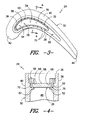
- FIG. 3 illustrates a top view of the turbine bucket 24.
- FIG. 4 illustrates a cross-sectional view of the turbine bucket 24 taken along line 4-4.
- the turbine bucket 24 generally includes a shank portion 28 and an airfoil 30 extending from a substantially planar platform 32.
- the platform 32 generally serves as the radially inward boundary for the hot gases of combustion flowing through the turbine section 16 of the gas turbine 10 ( FIG. 1 ).
- the shank portion 28 may generally be configured to extend radially inwardly from the platform 32 and may include a root structure (not shown), such as a dovetail, configured to secure the bucket 23 to the rotor disk 22 of the gas turbine 10 ( FIG. 1 ).
- the airfoil 30 may generally extend radially outwardly from the platform 32 and may include an airfoil base 34 disposed at the platform 32 and an airfoil tip 36 disposed opposite the airfoil base 34.
- the airfoil tip 36 may generally define the radially outermost portion of the turbine bucket 24.
- the airfoil 30 may also include a pressure side wall 38 and a suction side wall 40 ( FIGS. 3 and 4 ) extending between a leading edge 42 and a trailing edge 44.
- the pressure side wall 38 may generally comprise an aerodynamic, concave outer wall of the airfoil 30.
- the suction side wall 40 may generally define an aerodynamic, convex outer wall of the airfoil 30.
- the turbine bucket 24 may also include an airfoil cooling circuit 46 extending radially outwardly from the shank portion 28 for flowing a medium, such as a cooling medium (e.g., air, water, steam or any other suitable fluid), throughout the airfoil 30.
- a medium such as a cooling medium (e.g., air, water, steam or any other suitable fluid)
- the airfoil circuit 46 may generally have any suitable configuration known in the art.
- the airfoil circuit 46 may include a plurality of channels or passages 48 (one of which is shown in the cross-sectional view of FIG. 4 ) extending radially within the airfoil 30, such as from the airfoil base 34 to a location generally adjacent the airfoil tip 36.
- the airfoil circuit 46 may be configured as a multiple-pass cooling circuit, with the passages 48 being interconnected and extending radially inward and radially outward within the airfoil 30 (e.g., in a serpentine-like path) such that the medium within the passages 48 flows alternately radially outwardly and radially inwardly throughout the airfoil 30.
- the various components of the turbine bucket 24 may generally be formed from any suitable metal-based material.
- the turbine bucket 24 may be formed from nickel alloy steels, nickel-based superalloys, cobalt-based superalloys and/or any other suitable high-temperature alloys.
- application of the present subject matter need not be limited to the particular turbine bucket configuration and/or materials illustrated and described herein. Rather, the present subject matter may be beneficially applied to turbine buckets having any suitable configuration and/or turbine buckets formed from any suitable materials.
- the turbine bucket 24 may also include a separate tip cap 26 configured to be attached to the airfoil 30 at the airfoil tip 36 to generally provide a closed volume within the airfoil 30 and/or to retain the medium flowing through airfoil circuit 46 within the airfoil 30.
- the tip cap 26 may be configured to be attached to the airfoil 30 between the pressure side wall 38 and the suction side wall 40.
- the tip cap 26 may be shaped and/or otherwise dimensioned so that it may be positioned between the pressure side wall 38 and the suction side wall 40 ( FIGS. 3 and 4 ) at a location generally adjacent the airfoil tip 36. For example, as particularly shown in FIG.
- the tip cap 26 (the outer perimeter 50 of which is shown in dashed lines) may be configured to have a shape generally corresponding to the aerodynamic shape of the airfoil 30. As such, when the tip cap 26 is installed between the pressure side wall 38 and the suction side wall 40, the tip cap 26 may generally conform to the concave and convex shapes of the pressure and suction side walls 38, 40, respectively. However, in alternative embodiments, the tip cap 26 may have any other suitable shape that permits it to be positioned between the pressure and suction side walls 38, 40.
- the tip cap 26 may generally be configured to be supported between the pressure side wall 38 and the suction side wall 40 using any suitable structure and/or configuration known in the art.
- the turbine bucket 24 may include a shoulder 52 projecting inwardly from the pressure and suction side walls 38, 40.
- the tip cap 26 may be radially supported within the airfoil 30 at the airfoil tip 36 by the shoulder 52.
- turbine bucket 24 may include any other suitable feature for radially supporting the tip cap 26 within the airfoil 30.
- one or more dust holes 54 may be defmed through the tip cap 26 for expelling dust and/or other debris contained within the medium supplied through the airfoil circuit 46.
- the dust holes 54 may be defined in the tip cap 26 so as to be aligned with the passages 48 of the airfoil circuit 46. As such, any dust and/or debris carried within medium may be expelled from the passages 48 through the dust holes 54.
- the tip cap 26 may generally be formed from a ceramic matrix composite (CMC) material.
- CMC ceramic matrix composite
- the CMC material used to form the tip cap 26 may comprise any suitable CMC material known in the art and, thus, may generally include a ceramic matrix having a suitable reinforcing material incorporated therein to enhance the material's properties (e.g., the material strength and/or the thermo-physical properties).
- the CMC material used may be configured as a continuous fiber reinforced CMC material.
- suitable continuous fiber reinforced CMC materials may include, but are not limited to, CMC materials reinforced with continuous carbon fibers, oxide fibers, silicon carbide monofilament fibers and other CMC materials including continuous fiber lay-ups and/or woven fiber performs.
- the CMC material used may be configured as a discontinuous reinforced CMC material.
- suitable discontinuous reinforced CMC materials may include, but are not limited to, particulate, platelet, whisker, discontinuous fiber, in situ and nano-composite reinforced CMC materials.
- the disclosed tip cap 26 may be formed from the CMC material using any suitable manufacturing process known in the art.
- suitable manufacturing processes may include, but are not limited to, injection molding, slip casting, tape casting, infiltration methods (e.g., chemical vapor infiltration, melt infiltration and/or the like) and various other suitable methods and/or processes.
- the tip cap 26 may eliminate the need to utilize a portion of the medium flowing through the airfoil circuit 46 to cool the tip cap 26, thereby reducing the total amount of medium required to cool the turbine bucket 24 and increasing the overall efficiency of the gas turbine 10 ( FIG. 1 ). Additionally, the elimination of the need to cool the tip cap 26 may allow for the tip cap 26 to be designed without the film cooling holes typically required for metal-based tip caps, thereby reducing the component's complexity and also reducing manufacturing costs. Moreover, CMC materials generally have a lower density than metal-based materials. Thus, the tip cap 26 may have a reduced weight as compared to similarly configured metal-based tip caps, thereby reducing the load generated by the tip cap 26 during operation of the gas turbine 10. As such, the total stress acting on the turbine bucket 24 may be reduced.
- the retaining ring 56 may be attached between the pressure and suction side walls 38, 40 using any suitable attachment method known in the art.
- the retaining ring 56 may be welded or brazed to the pressure and/or suction side walls 38, 40.
- the retaining ring 56 may be configured to be welded or brazed to the pressure and suction side 38, 40 walls along the entire inner perimeter of the airfoil 30.
- the retaining ring 56 may be attached between the pressure and suction side walls 38, 40 using various other suitable attachment methods, such as by using suitable fastening mechanisms (e.g., bolts, screws, retaining pins, brackets, rivets, and/or other suitable mechanical fasteners).
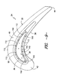
- the medium supplied though the airfoil circuit 48 may be directed through the cooling holes 70 to provide impingement and/or film cooling around the inner perimeter of the airfoil 30 and at the airfoil tip 36.
- the cooling holes 70 may have any other suitable arrangement within the turbine bucket 24 that provides beneficial cooling to the inner perimeter of the airfoil 30 and/or the airfoil tip 36.
- the cooling holes 70 may only be defined through portions of the tip cap 26 and the retaining ring 56. In another embodiment, the cooling holes may only be defined through the tip cap 26.
- the pressure and suction side walls 38, 40 may initially include flared ends 60 configured to be angled outwardly at the airfoil tip 36.
- the flared ends 60 may be designed to be angled outwardly a sufficient width 62 such that the tip cap 26 may be inserted between the pressure and suction side walls 38, 40 and positioned onto a radially inner shoulder 64 projecting inwardly from the side walls 38, 40.
- the flared ends 60 may be straightened and/or otherwise formed into the configuration shown in FIG. 6 , wherein the tip cap 26 is captured between the radially inner shoulder 64 and a radially outer shoulder 66 projecting inwardly from the pressure and suction side walls 38, 40 so that a sealing surface 72 may be defined at the interface between the tip cap 26 and the radially outer shoulder 66. As such, the tip cap 26 may be securely retained between the pressure and suction side walls 38, 40. Additionally, upon the straightening of the flared ends 60, the pressure and suction side walls 38, 40 may generally define a smooth, aerodynamic contour along the entire radial height of the airfoil 30. It should be appreciated that the flared ends 60 may be straightened using any suitable method known in the art, such as by crimping, rolling and/or bending the flared ends 60 into the configuration shown in FIG. 6 .
- the tip cap 26 may be radially retained within the airfoil 30 and a sealing surface 108 may be defined at the interface between the ring sections 100, 102 and the tip cap 26.
- the first and second retaining ring sections 100, 102 may generally have any suitable shape and/or configuration that allows such ring sections 100, 102 to function as described herein.
- the retaining ring sections 100, 102 may be configured to have a shape generally corresponding to the aerodynamic shape of both the airfoil 30 and the tip cap 26.
- the first retaining ring section 100 may generally have a shape corresponding to aerodynamic shape of both the pressure side wall 38 and the corresponding side of the tip cap 26
- the second retaining ring section 102 may generally have a shape corresponding to the aerodynamic shape of both the suction side wall 40 and the corresponding side of the tip cap 26.
- the retaining ring sections 100, 102 may have any other suitable shape that permits the ring sections 100, 102 to be attached between the pressure and suction side walls 38, 40 so as to radially retain the tip cap 26 within the airfoil 30.
Landscapes
- Engineering & Computer Science (AREA)
- Chemical & Material Sciences (AREA)
- Mechanical Engineering (AREA)
- General Engineering & Computer Science (AREA)
- Materials Engineering (AREA)
- Composite Materials (AREA)
- Architecture (AREA)
- Ceramic Engineering (AREA)
- Turbine Rotor Nozzle Sealing (AREA)
Applications Claiming Priority (1)
| Application Number | Priority Date | Filing Date | Title |
|---|---|---|---|
| US13/149,426 US8734107B2 (en) | 2011-05-31 | 2011-05-31 | Ceramic-based tip cap for a turbine bucket |
Publications (2)
| Publication Number | Publication Date |
|---|---|
| EP2570594A2 true EP2570594A2 (fr) | 2013-03-20 |
| EP2570594A3 EP2570594A3 (fr) | 2014-06-18 |
Family
ID=46148742
Family Applications (1)
| Application Number | Title | Priority Date | Filing Date |
|---|---|---|---|
| EP12169739.5A Withdrawn EP2570594A3 (fr) | 2011-05-31 | 2012-05-29 | Aube de turbine avec profil métallique et couvercle d'extrémité céramique et moteur à turbine à gaz associé |
Country Status (3)
| Country | Link |
|---|---|
| US (1) | US8734107B2 (fr) |
| EP (1) | EP2570594A3 (fr) |
| CN (1) | CN102808655B (fr) |
Cited By (2)
| Publication number | Priority date | Publication date | Assignee | Title |
|---|---|---|---|---|
| EP2636846A1 (fr) * | 2012-03-06 | 2013-09-11 | General Electric Company | Profil de turbine fabriqué |
| US10370979B2 (en) | 2015-11-23 | 2019-08-06 | United Technologies Corporation | Baffle for a component of a gas turbine engine |
Families Citing this family (10)
| Publication number | Priority date | Publication date | Assignee | Title |
|---|---|---|---|---|
| US9050769B2 (en) * | 2012-04-13 | 2015-06-09 | General Electric Company | Pre-form ceramic matrix composite cavity and method of forming and method of forming a ceramic matrix composite component |
| CN105899761B (zh) * | 2014-01-17 | 2017-10-17 | 通用电气公司 | 带有张开部的陶瓷基复合材料涡轮叶片凹槽状叶顶及其方法 |
| GB201406472D0 (en) * | 2014-04-10 | 2014-05-28 | Rolls Royce Plc | Rotor blade |
| SG10201505408WA (en) * | 2014-07-24 | 2016-02-26 | United Technologies Corp | Gas turbine engine blade with variable density and wide chord tip |
| US10227878B2 (en) * | 2016-03-10 | 2019-03-12 | General Electric Company | Article and method of forming an article |
| US20180298765A1 (en) * | 2017-04-14 | 2018-10-18 | General Electric Company | Engine component with replaceable tip element |
| EP3473808B1 (fr) * | 2017-10-19 | 2020-06-17 | Siemens Aktiengesellschaft | Pale d'aube pour une aube mobile de turbine à refroidissement intérieur ainsi que procédé de fabrication d'une telle pale |
| US11203938B2 (en) | 2018-11-08 | 2021-12-21 | General Electric Company | Airfoil coupon attachment |
| US11143033B2 (en) * | 2018-11-08 | 2021-10-12 | General Electric Company | Turbomachine blade tip attachment |
| US12116903B2 (en) * | 2021-06-30 | 2024-10-15 | General Electric Company | Composite airfoils with frangible tips |
Family Cites Families (21)
| Publication number | Priority date | Publication date | Assignee | Title |
|---|---|---|---|---|
| US3628885A (en) * | 1969-10-01 | 1971-12-21 | Gen Electric | Fluid-cooled airfoil |
| US3732031A (en) * | 1970-06-17 | 1973-05-08 | Gen Motors Corp | Cooled airfoil |
| US4020538A (en) | 1973-04-27 | 1977-05-03 | General Electric Company | Turbomachinery blade tip cap configuration |
| US3899267A (en) * | 1973-04-27 | 1975-08-12 | Gen Electric | Turbomachinery blade tip cap configuration |
| US4010531A (en) * | 1975-09-02 | 1977-03-08 | General Electric Company | Tip cap apparatus and method of installation |
| US4589824A (en) * | 1977-10-21 | 1986-05-20 | United Technologies Corporation | Rotor blade having a tip cap end closure |
| US4247254A (en) * | 1978-12-22 | 1981-01-27 | General Electric Company | Turbomachinery blade with improved tip cap |
| US4411597A (en) * | 1981-03-20 | 1983-10-25 | The United States Of America As Represented By The Administrator Of The National Aeronautics And Space Administration | Tip cap for a rotor blade |
| US5015540A (en) * | 1987-06-01 | 1991-05-14 | General Electric Company | Fiber-containing composite |
| US5192192A (en) | 1990-11-28 | 1993-03-09 | The United States Of America As Represented By The Secretary Of The Air Force | Turbine engine foil cap |
| EP0513407B1 (fr) * | 1991-05-13 | 1995-07-19 | Asea Brown Boveri Ag | Procédé de fabrication d' une aube de turbine |
| US6367687B1 (en) * | 2001-04-17 | 2002-04-09 | General Electric Company | Method for preparing a plate rim for brazing |
| US6634860B2 (en) | 2001-12-20 | 2003-10-21 | General Electric Company | Foil formed structure for turbine airfoil tip |
| EP1329592A1 (fr) * | 2002-01-18 | 2003-07-23 | Siemens Aktiengesellschaft | Turbine avec au moins quatre stages et utilisation des aubes en masse réduite |
| US20050091848A1 (en) * | 2003-11-03 | 2005-05-05 | Nenov Krassimir P. | Turbine blade and a method of manufacturing and repairing a turbine blade |
| US7001151B2 (en) | 2004-03-02 | 2006-02-21 | General Electric Company | Gas turbine bucket tip cap |
| FR2878458B1 (fr) * | 2004-11-26 | 2008-07-11 | Snecma Moteurs Sa | Procede de fabrication de noyaux ceramiques de fonderie pour aubes de turbomachines, outil pour la mise en oeuvre du procede |
| US7419363B2 (en) * | 2005-05-13 | 2008-09-02 | Florida Turbine Technologies, Inc. | Turbine blade with ceramic tip |
| US7556477B2 (en) | 2005-10-04 | 2009-07-07 | General Electric Company | Bi-layer tip cap |
| US7537431B1 (en) | 2006-08-21 | 2009-05-26 | Florida Turbine Technologies, Inc. | Turbine blade tip with mini-serpentine cooling circuit |
| US8366392B1 (en) * | 2009-05-06 | 2013-02-05 | Florida Turbine Technologies, Inc. | Composite air cooled turbine rotor blade |
-
2011
- 2011-05-31 US US13/149,426 patent/US8734107B2/en not_active Expired - Fee Related
-
2012
- 2012-05-29 EP EP12169739.5A patent/EP2570594A3/fr not_active Withdrawn
- 2012-05-31 CN CN201210175031.1A patent/CN102808655B/zh not_active Expired - Fee Related
Non-Patent Citations (1)
| Title |
|---|
| None |
Cited By (3)
| Publication number | Priority date | Publication date | Assignee | Title |
|---|---|---|---|---|
| EP2636846A1 (fr) * | 2012-03-06 | 2013-09-11 | General Electric Company | Profil de turbine fabriqué |
| US10370979B2 (en) | 2015-11-23 | 2019-08-06 | United Technologies Corporation | Baffle for a component of a gas turbine engine |
| US11035236B2 (en) | 2015-11-23 | 2021-06-15 | Raytheon Technologies Corporation | Baffle for a component of a gas turbine engine |
Also Published As
| Publication number | Publication date |
|---|---|
| EP2570594A3 (fr) | 2014-06-18 |
| CN102808655A (zh) | 2012-12-05 |
| CN102808655B (zh) | 2016-03-16 |
| US8734107B2 (en) | 2014-05-27 |
| US20120308392A1 (en) | 2012-12-06 |
Similar Documents
| Publication | Publication Date | Title |
|---|---|---|
| US8734107B2 (en) | Ceramic-based tip cap for a turbine bucket | |
| EP3091187B1 (fr) | Agencement de composant de turbine avec fixation exempte de contrainte thermique | |
| US20140212284A1 (en) | Hybrid turbine nozzle | |
| US10822973B2 (en) | Shroud for a gas turbine engine | |
| AU672922B2 (en) | Gas turbine vane | |
| US7828515B1 (en) | Multiple piece turbine airfoil | |
| EP2578807A2 (fr) | Profil aérodynamique pour système de turbine | |
| CN102678188B (zh) | 涡轮叶片组件 | |
| EP1775421A2 (fr) | Assemblage pour contròler les tensions thermiques dans un composite à matrice céramique | |
| EP2592231B1 (fr) | Joint métallique flexible pour conduit de transition dans un système de turbine | |
| US20180037511A1 (en) | Turbine | |
| CN105917081A (zh) | 基于模块化结构的导叶组件 | |
| EP2447475B1 (fr) | Agencement de fixation d'une aube | |
| EP3835553B1 (fr) | Ensemble joint de plaque latérale non métallique pour un moteur à turbine à gaz | |
| EP2636846A1 (fr) | Profil de turbine fabriqué | |
| EP3751103B1 (fr) | Fixation de pale de rotor composite à matrice céramique | |
| US10436041B2 (en) | Shroud assembly for turbine systems | |
| WO2017039607A1 (fr) | Insert de pale de turbine | |
| US11401834B2 (en) | Method of securing a ceramic matrix composite (CMC) component to a metallic substructure using CMC straps | |
| EP3808940B1 (fr) | Surface portante en cmc pour un moteur à turbine à gaz comportant des trous de refroidissement | |
| Kimmel | Multiple piece turbine airfoil | |
| EP4469664A2 (fr) | Composants pour turbines à gaz |
Legal Events
| Date | Code | Title | Description |
|---|---|---|---|
| PUAI | Public reference made under article 153(3) epc to a published international application that has entered the european phase |
Free format text: ORIGINAL CODE: 0009012 |
|
| AK | Designated contracting states |
Kind code of ref document: A2 Designated state(s): AL AT BE BG CH CY CZ DE DK EE ES FI FR GB GR HR HU IE IS IT LI LT LU LV MC MK MT NL NO PL PT RO RS SE SI SK SM TR |
|
| AX | Request for extension of the european patent |
Extension state: BA ME |
|
| PUAL | Search report despatched |
Free format text: ORIGINAL CODE: 0009013 |
|
| AK | Designated contracting states |
Kind code of ref document: A3 Designated state(s): AL AT BE BG CH CY CZ DE DK EE ES FI FR GB GR HR HU IE IS IT LI LT LU LV MC MK MT NL NO PL PT RO RS SE SI SK SM TR |
|
| AX | Request for extension of the european patent |
Extension state: BA ME |
|
| RIC1 | Information provided on ipc code assigned before grant |
Ipc: F01D 5/28 20060101ALI20140512BHEP Ipc: C04B 35/80 20060101ALI20140512BHEP Ipc: F01D 5/14 20060101AFI20140512BHEP Ipc: F01D 5/20 20060101ALI20140512BHEP Ipc: B23P 15/04 20060101ALI20140512BHEP |
|
| 17P | Request for examination filed |
Effective date: 20141218 |
|
| RBV | Designated contracting states (corrected) |
Designated state(s): AL AT BE BG CH CY CZ DE DK EE ES FI FR GB GR HR HU IE IS IT LI LT LU LV MC MK MT NL NO PL PT RO RS SE SI SK SM TR |
|
| STAA | Information on the status of an ep patent application or granted ep patent |
Free format text: STATUS: THE APPLICATION IS DEEMED TO BE WITHDRAWN |
|
| 18D | Application deemed to be withdrawn |
Effective date: 20171201 |