EP2570613A2 - Vorderkantenkernkonfiguration für eine äußere Laufschaufelluftdichtungsanordnung - Google Patents
Vorderkantenkernkonfiguration für eine äußere Laufschaufelluftdichtungsanordnung Download PDFInfo
- Publication number
- EP2570613A2 EP2570613A2 EP12184439A EP12184439A EP2570613A2 EP 2570613 A2 EP2570613 A2 EP 2570613A2 EP 12184439 A EP12184439 A EP 12184439A EP 12184439 A EP12184439 A EP 12184439A EP 2570613 A2 EP2570613 A2 EP 2570613A2
- Authority
- EP
- European Patent Office
- Prior art keywords
- blade outer
- outer air
- air seal
- channel
- leading
- Prior art date
- Legal status (The legal status is an assumption and is not a legal conclusion. Google has not performed a legal analysis and makes no representation as to the accuracy of the status listed.)
- Granted
Links
- 238000001816 cooling Methods 0.000 claims abstract description 86
- 230000004888 barrier function Effects 0.000 claims abstract description 38
- 238000005266 casting Methods 0.000 claims description 5
- 230000003068 static effect Effects 0.000 description 4
- 230000000712 assembly Effects 0.000 description 3
- 238000000429 assembly Methods 0.000 description 3
- 238000002485 combustion reaction Methods 0.000 description 3
- 230000037406 food intake Effects 0.000 description 3
- 241000270299 Boa Species 0.000 description 2
- 238000003491 array Methods 0.000 description 1
- 230000008901 benefit Effects 0.000 description 1
- 239000000919 ceramic Substances 0.000 description 1
- 239000000446 fuel Substances 0.000 description 1
- 238000005495 investment casting Methods 0.000 description 1
- 239000000463 material Substances 0.000 description 1
- 238000000034 method Methods 0.000 description 1
- 238000012986 modification Methods 0.000 description 1
- 230000004048 modification Effects 0.000 description 1
- 230000008569 process Effects 0.000 description 1
- 230000004044 response Effects 0.000 description 1
- 230000007704 transition Effects 0.000 description 1
Images


Classifications
-
- F—MECHANICAL ENGINEERING; LIGHTING; HEATING; WEAPONS; BLASTING
- F01—MACHINES OR ENGINES IN GENERAL; ENGINE PLANTS IN GENERAL; STEAM ENGINES
- F01D—NON-POSITIVE DISPLACEMENT MACHINES OR ENGINES, e.g. STEAM TURBINES
- F01D11/00—Preventing or minimising internal leakage of working-fluid, e.g. between stages
- F01D11/005—Sealing means between non relatively rotating elements
-
- F—MECHANICAL ENGINEERING; LIGHTING; HEATING; WEAPONS; BLASTING
- F01—MACHINES OR ENGINES IN GENERAL; ENGINE PLANTS IN GENERAL; STEAM ENGINES
- F01D—NON-POSITIVE DISPLACEMENT MACHINES OR ENGINES, e.g. STEAM TURBINES
- F01D11/00—Preventing or minimising internal leakage of working-fluid, e.g. between stages
- F01D11/001—Preventing or minimising internal leakage of working-fluid, e.g. between stages for sealing space between stator blade and rotor
-
- F—MECHANICAL ENGINEERING; LIGHTING; HEATING; WEAPONS; BLASTING
- F01—MACHINES OR ENGINES IN GENERAL; ENGINE PLANTS IN GENERAL; STEAM ENGINES
- F01D—NON-POSITIVE DISPLACEMENT MACHINES OR ENGINES, e.g. STEAM TURBINES
- F01D11/00—Preventing or minimising internal leakage of working-fluid, e.g. between stages
- F01D11/08—Preventing or minimising internal leakage of working-fluid, e.g. between stages for sealing space between rotor blade tips and stator
-
- F—MECHANICAL ENGINEERING; LIGHTING; HEATING; WEAPONS; BLASTING
- F01—MACHINES OR ENGINES IN GENERAL; ENGINE PLANTS IN GENERAL; STEAM ENGINES
- F01D—NON-POSITIVE DISPLACEMENT MACHINES OR ENGINES, e.g. STEAM TURBINES
- F01D11/00—Preventing or minimising internal leakage of working-fluid, e.g. between stages
- F01D11/08—Preventing or minimising internal leakage of working-fluid, e.g. between stages for sealing space between rotor blade tips and stator
- F01D11/14—Adjusting or regulating tip-clearance, i.e. distance between rotor-blade tips and stator casing
- F01D11/16—Adjusting or regulating tip-clearance, i.e. distance between rotor-blade tips and stator casing by self-adjusting means
- F01D11/18—Adjusting or regulating tip-clearance, i.e. distance between rotor-blade tips and stator casing by self-adjusting means using stator or rotor components with predetermined thermal response, e.g. selective insulation, thermal inertia, differential expansion
-
- F—MECHANICAL ENGINEERING; LIGHTING; HEATING; WEAPONS; BLASTING
- F01—MACHINES OR ENGINES IN GENERAL; ENGINE PLANTS IN GENERAL; STEAM ENGINES
- F01D—NON-POSITIVE DISPLACEMENT MACHINES OR ENGINES, e.g. STEAM TURBINES
- F01D11/00—Preventing or minimising internal leakage of working-fluid, e.g. between stages
- F01D11/08—Preventing or minimising internal leakage of working-fluid, e.g. between stages for sealing space between rotor blade tips and stator
- F01D11/14—Adjusting or regulating tip-clearance, i.e. distance between rotor-blade tips and stator casing
- F01D11/20—Actively adjusting tip-clearance
- F01D11/24—Actively adjusting tip-clearance by selectively cooling-heating stator or rotor components
-
- F—MECHANICAL ENGINEERING; LIGHTING; HEATING; WEAPONS; BLASTING
- F01—MACHINES OR ENGINES IN GENERAL; ENGINE PLANTS IN GENERAL; STEAM ENGINES
- F01D—NON-POSITIVE DISPLACEMENT MACHINES OR ENGINES, e.g. STEAM TURBINES
- F01D25/00—Component parts, details, or accessories, not provided for in, or of interest apart from, other groups
- F01D25/24—Casings; Casing parts, e.g. diaphragms, casing fastenings
- F01D25/246—Fastening of diaphragms or stator-rings
-
- F—MECHANICAL ENGINEERING; LIGHTING; HEATING; WEAPONS; BLASTING
- F01—MACHINES OR ENGINES IN GENERAL; ENGINE PLANTS IN GENERAL; STEAM ENGINES
- F01D—NON-POSITIVE DISPLACEMENT MACHINES OR ENGINES, e.g. STEAM TURBINES
- F01D9/00—Stators
- F01D9/02—Nozzles; Nozzle boxes; Stator blades; Guide conduits, e.g. individual nozzles
- F01D9/04—Nozzles; Nozzle boxes; Stator blades; Guide conduits, e.g. individual nozzles forming ring or sector
-
- F—MECHANICAL ENGINEERING; LIGHTING; HEATING; WEAPONS; BLASTING
- F01—MACHINES OR ENGINES IN GENERAL; ENGINE PLANTS IN GENERAL; STEAM ENGINES
- F01D—NON-POSITIVE DISPLACEMENT MACHINES OR ENGINES, e.g. STEAM TURBINES
- F01D9/00—Stators
- F01D9/02—Nozzles; Nozzle boxes; Stator blades; Guide conduits, e.g. individual nozzles
- F01D9/04—Nozzles; Nozzle boxes; Stator blades; Guide conduits, e.g. individual nozzles forming ring or sector
- F01D9/041—Nozzles; Nozzle boxes; Stator blades; Guide conduits, e.g. individual nozzles forming ring or sector using blades
-
- F—MECHANICAL ENGINEERING; LIGHTING; HEATING; WEAPONS; BLASTING
- F05—INDEXING SCHEMES RELATING TO ENGINES OR PUMPS IN VARIOUS SUBCLASSES OF CLASSES F01-F04
- F05D—INDEXING SCHEME FOR ASPECTS RELATING TO NON-POSITIVE-DISPLACEMENT MACHINES OR ENGINES, GAS-TURBINES OR JET-PROPULSION PLANTS
- F05D2240/00—Components
- F05D2240/10—Stators
- F05D2240/11—Shroud seal segments
-
- F—MECHANICAL ENGINEERING; LIGHTING; HEATING; WEAPONS; BLASTING
- F05—INDEXING SCHEMES RELATING TO ENGINES OR PUMPS IN VARIOUS SUBCLASSES OF CLASSES F01-F04
- F05D—INDEXING SCHEME FOR ASPECTS RELATING TO NON-POSITIVE-DISPLACEMENT MACHINES OR ENGINES, GAS-TURBINES OR JET-PROPULSION PLANTS
- F05D2250/00—Geometry
- F05D2250/10—Two-dimensional
- F05D2250/13—Two-dimensional trapezoidal
-
- F—MECHANICAL ENGINEERING; LIGHTING; HEATING; WEAPONS; BLASTING
- F05—INDEXING SCHEMES RELATING TO ENGINES OR PUMPS IN VARIOUS SUBCLASSES OF CLASSES F01-F04
- F05D—INDEXING SCHEME FOR ASPECTS RELATING TO NON-POSITIVE-DISPLACEMENT MACHINES OR ENGINES, GAS-TURBINES OR JET-PROPULSION PLANTS
- F05D2250/00—Geometry
- F05D2250/30—Arrangement of components
- F05D2250/31—Arrangement of components according to the direction of their main axis or their axis of rotation
- F05D2250/314—Arrangement of components according to the direction of their main axis or their axis of rotation the axes being inclined in relation to each other
-
- F—MECHANICAL ENGINEERING; LIGHTING; HEATING; WEAPONS; BLASTING
- F05—INDEXING SCHEMES RELATING TO ENGINES OR PUMPS IN VARIOUS SUBCLASSES OF CLASSES F01-F04
- F05D—INDEXING SCHEME FOR ASPECTS RELATING TO NON-POSITIVE-DISPLACEMENT MACHINES OR ENGINES, GAS-TURBINES OR JET-PROPULSION PLANTS
- F05D2250/00—Geometry
- F05D2250/70—Shape
- F05D2250/75—Shape given by its similarity to a letter, e.g. T-shaped
-
- F—MECHANICAL ENGINEERING; LIGHTING; HEATING; WEAPONS; BLASTING
- F05—INDEXING SCHEMES RELATING TO ENGINES OR PUMPS IN VARIOUS SUBCLASSES OF CLASSES F01-F04
- F05D—INDEXING SCHEME FOR ASPECTS RELATING TO NON-POSITIVE-DISPLACEMENT MACHINES OR ENGINES, GAS-TURBINES OR JET-PROPULSION PLANTS
- F05D2260/00—Function
- F05D2260/20—Heat transfer, e.g. cooling
- F05D2260/221—Improvement of heat transfer
- F05D2260/2214—Improvement of heat transfer by increasing the heat transfer surface
- F05D2260/22141—Improvement of heat transfer by increasing the heat transfer surface using fins or ribs
-
- Y—GENERAL TAGGING OF NEW TECHNOLOGICAL DEVELOPMENTS; GENERAL TAGGING OF CROSS-SECTIONAL TECHNOLOGIES SPANNING OVER SEVERAL SECTIONS OF THE IPC; TECHNICAL SUBJECTS COVERED BY FORMER USPC CROSS-REFERENCE ART COLLECTIONS [XRACs] AND DIGESTS
- Y02—TECHNOLOGIES OR APPLICATIONS FOR MITIGATION OR ADAPTATION AGAINST CLIMATE CHANGE
- Y02T—CLIMATE CHANGE MITIGATION TECHNOLOGIES RELATED TO TRANSPORTATION
- Y02T50/00—Aeronautics or air transport
- Y02T50/60—Efficient propulsion technologies, e.g. for aircraft
Definitions
- This disclosure relates to a blade outer air seal (BOAS) and, more particularly, to a multi-channel blade outer air seal (BOAS).
- BOAS blade outer air seal
- BOAS multi-channel blade outer air seal
- Gas turbine engines generally include fan, compressor, combustor and turbine sections along an engine axis of rotation.
- the fan, compressor, and turbine sections each include a series of stator and rotor blade assemblies.
- a rotor and an axially adjacent array of stator assemblies may be referred to as a stage.
- Each stator vane assembly increases efficiency through the direction of core gas flow into or out of the rotor assemblies.
- An outer case including a multiple of blade outer air seals (BOAS), provides an outer radial flow path boundary.
- a multiple of BOAS are typically provided to accommodate thermal and dynamic variation typical in a high pressure turbine (HPT) section of the gas turbine engine.
- the BOAS are subjected to relatively high temperatures and receive a secondary cooling airflow for temperature control.
- the secondary cooling airflow is communicated into the BOAS then through cooling channels within the BOAS for temperature control.
- the cooling channels used to communicate the cooling air through the blade outer air seal can provide entry points for hot gas ingestion if the back flow margin is not high enough.
- An example blade outer air seal assembly may consist of a blade outer air seal containing channels that communicate cooling air through at least some of the blade outer air seal.
- the blade outer air seal has at least one circumferentially extending barrier separating the leading channel into a forward portion and an aft portion. Cooling air outlets from the leading channel are exclusively coupled to the aft portion.
- An example blade outer air seal casting core includes a core having a first open area configured to establish a corresponding axially extending barrier within a channel of a blade outer air seal, and a second open area configured to establish a corresponding circumferentially extending barrier within the channel of the blade outer air seal.
- the first open area may be positioned near a circumferential midpoint of the core.
- a blade outer air seal cooling method including introducing cooling air to a leading channel established in a blade outer air seal, and communicating cooling air away from the leading channel using, exclusively, one or more outlets coupled with an aft portion of the leading channel.
- an example turbomachine such as a gas turbine engine 10 is circumferentially disposed about an axis 12.
- the gas turbine engine 10 includes a fan section 14, a low-pressure compressor section 16, a high-pressure compressor section 18, a combustion section 20, a high-pressure turbine section 22, and a low-pressure turbine section 24.
- Other example turbomachines may include more or fewer sections.
- the high-pressure compressor section 18 includes a rotor 32.
- the low-pressure compressor section 16 includes a rotor 34.
- the rotors 32 and 34 are configured to rotate about the axis 12.
- the example rotors 32 and 34 include alternating rows of rotatable airfoils or rotatable blades 36 and static airfoils or static blades 38.
- the high-pressure turbine section 22 includes a rotor 40 that is rotatably coupled to the rotor 32.
- the low-pressure turbine section 24 includes a rotor 42 that is rotatably coupled to the rotor 34.
- the rotors 40 and 42 are configured to rotate about the axis 12 in response to expansion to drive the high-pressure compressor section 18 and the low-pressure compressor section 16.
- the example rotors 40 and 42 include alternating rows of rotatable airfoils or rotatable blades 44 and static airfoils or static vanes 46.
- the examples described in this disclosure is not limited to the two-spool gas turbine architecture described, and may be used in other architectures, such as a single-spool axial design, a three-spool axial design, and still other architectures. That is, these are various types of gas turbine engines, and other turbomachines, that can benefit from the examples disclosed herein.
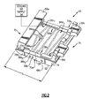
- an example blade outer air seal (BOAS) 50 is suspended from an outer casing of the gas turbine engine 10.
- the BOAS 50 is located within the high-pressure turbine section 22 of the gas turbine engine 10.
- an inwardly facing surface 52 of the example BOAS 50 interfaces and seals against tips of blades 44 in known manner.
- Attachment structures are used to secure the BOAS 50 within the engine 10.
- the attachment structures in this example include a leading hook 5 5a and a trailing hook 55b.
- the BOAS 50 is one of a group of several BOASs that circumscribe the rotor 42.
- the BOAS 50 establishes an outer diameter of the core flow path through the engine 10.
- Other areas of the engine 10 include other circumferential ring arrays of BOASs that circumscribe a particular blade stage of the engine 10.
- Cooling air is moved through the BOAS 50 to communicate thermal energy away from the BOAS 50.
- the cooling air moves from a cooling air supply 54 through apertures, such as inlet holes 56a 1 - 56e, established in an outwardly facing surface 58 of the BOAS 50.
- the cooling air supply 54 is located radially outboard from the BOAS 50.
- Cooling air moves radially through the inlet holes 56a 1 -56a 4 into a channel 66a established within the BOAS 50.
- the inlet holes 56a 1 and 56a 2 are considered primary inlet holes, and the inlet holes 56a 3 and 56a 4 are secondary inlet holes (or optional resupply holes).
- Cooling air also moves radially through the inlet holes 56b into a cavity 66b, through the inlet holes 56c into a channel 66c, through the inlet holes 56d into a channel 66d, and through the inlet holes 56e into a channel 66e. Cooling air is not free to move between the cavities 66a-66e after entering the cavities 66a-66e.
- the outlet holes 68a 1 and 68a 2 communicate cooling air away from the channel 66a exclusively.
- the outlet hole 68b communicates cooling air away from the channel 66b
- the outlet hole 68c communicates cooling air away from the channel 66c, etc.
- the cooling air moves circumferentially as the cooling air exits the BOAS 50 through the outlet holes 68a 1 -68e.
- the cooling air moving from the outlet holes 68a 1 -68e contacts a circumferentially adjacent BOAS within the engine 10.
- the BOAS 50 may interface with the circumferentially adjacent BOAS through a shiplapped joint, for example.
- the example BOAS 50 extends axially from a leading edge 72 to a trailing edge 74. Notably, the outlet holes 68a 1 -68e in the example BOAS 50 are spaced from the leading edge 72.
- the channel 66a is considered a leading channel as the channel 66a is the channel of BOAS that is closest to the leading edge 72.
- outlet holes 68a1 through 68e are axially spaced from the leading edge 72.
- the channel 66a closest to the leading edge 72 includes a front edge 75a and a rear edge 75b.
- the outlet holes 68a 1 and 68a 2 are each aft the front edge 75a.
- each of the outlet holes 68a 1 and 68a 2 (in this example) is aft the leading hook 55a.
- the remaining channels 66b-66e (and their respective outlet holes 68b-68e) are aft of channel 66a.
- the outlet holes 68a 1 and 68a 2 are each closer to the rear edge 75b than the front edge 75a.
- the gas path pressure of the main flow path through the engine 10 is lower near the axially trailing edge 74 than the axially leading edge 72.
- moving cooling air outlet holes 68a and 68a 2 rearward increases back flow margin and lessens the likelihood of ingestion from the main flow path into the channel 66a.
- features of the BOAS 50 manipulate flow of cooling air through the channel 66a.
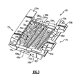
- Such features include axially extending barriers 76a and 76b, circumferentially extending barriers 78a and 78b, and trip strips 80.
- the cavities 66b-66e also include trip strips 80, but do not include axially or circumferentially extending barriers.
- the example axially extending barriers 76a and 76b project radially from an inner diameter surface 82 of the channel 66a and contact the outwardly facing surface 58.
- the axially extending barrier 76a is a leading axial barrier.
- the axially extending barrier 76b is a trailing axial barrier.
- the example axially extending barriers 76a and 76b are positioned near a circumferential middle of the channel 66a and limit circumferential flow of cooling air through the channel 66a.
- the barriers 76a and 76b are axially aligned with the axis of rotation 12 ( Figure 1 ).
- the barriers 76a and 76b are also perpendicular to the front edge 75a.
- the example circumferentially extending barriers 78a and 78b also project radially from the inner diameter surface 82 of the channel 66 and contact the outwardly facing surface 58.
- the example barriers 78a and 78b are designed to maximize heat transfer coefficients in the channel 66a.
- the example circumferentially extending barriers 78a and 78b are tapered relative to the front edge 75a and the rear edge 75b, which help focus flow of cooling air within the channel 66a and limits axial flow of cooling air through the channel 66a.
- the circumferentially extending barriers 78a and 78b are both tapered toward the axially extending barrier 76a.
- the trip strips 80 project radially from the inner diameter surface 82 of the channel 66a, but do not contact the outwardly facing surface 58.
- the trip strips 80 turbulate flow of cooling air within the channel 66a, which facilitates transfer of thermal energy from the BOAS 50 to the cooling air.
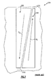
- the channel 66a is formed within the BOAS 50 using an investment casting process.
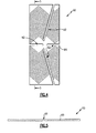
- a ceramic core 90 can be used during the casting process to establish the channel 66a and the features within the channel 66a.
- Open areas 92 of the core 90 receive material that establishes the barriers 76a, 76b, 78a, and 78b.
- Grooves 98 in the core 90 establish the trip strips 80.
- the other cavities 66b-66e are formed using other cores (not shown).
- the circumferentially extending barriers 78a and 78b divide the channel 66a into a forward channel portion 100 and an aft channel portion 102.
- cooling air entering the channel 66a through the primary inlet holes 56a 1 moves generally along path P 1
- cooling air entering the channel 66 through primary inlet holes 56a 2 moves generally along path P 2 .
- the paths P 1 and P 2 are both in the forward channel portion 100.
- Cooling air moving along the paths P 1 and P 2 contacts the barrier 76a, which redirects cooling air moving along the paths P 1 and P 2 through one or both of the openings 86 and 88.
- the opening 86 is established between the barriers 76b and 78a.
- the opening 88 is established between the barriers 76b and 78b.
- the cooling air transitions from the forward channel portion 100 to the aft channel portion 102 as the cooling air moves through one of the openings 86 or 88.
- Cooling air that has moved through the opening 86 then moves generally in a direction P 3 to the corresponding outlet hole 68a 2 . Cooling air that has moved through the opening 88 moves generally in a direction P 4 to the other one of the outlet holes 68a 1 . Cooling air that has moved along the path P 1 and is redirected into the opening 86 thus flows in opposite circumferential directions within the channel 66a. Similarly, cooling air that has moved along path P 2 and is redirected into the opening 88 flows in opposite circumferential directions within the channel 66a.
- the outlet holes 68a 1 and 68a 2 are both within (or coupled to) the aft channel portion 102.
- Additional cooling air may be introduced to the channel 66a though the resupply inlet holes 56a 3 . This additional cooling air is combined with the cooling air that has moved through the opening 86 and is moving along the path P 3 . Additional cooling air may be introduced to the channel 66a though the resupply inlet hole 56a 4 . This additional cooling air is combined with the cooling air that has moved through the opening 88 and is moving along the path P 4 .
- the resupply inlet holes 56a 3 and 56a 4 are optional. That is, the primary inlet holes 56a and 56b may be used exclusively to move air into the channel 66a.
- tapering the barriers 78a and 78b focuses flow of cooling air toward the barrier 76a when the air moves along the paths P 1 and P 2 , and focuses flow of cooling air toward one of the outlet holes 68a 1 and 68a 2 when the air moves along the paths P 3 and P 4 .
- the example barriers 76a, 76b, 78a, and 78b do not extend across the entire channel 66a.
- the channel 66a is considered a single channel separate from the other cavities 66b-66e.
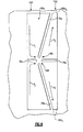
- leading edge cavities 200 and 204 in a prior art blade outer air seal 208 communicate air along a path P 5 or P 6 in a single circumferential direction.
- the air moving along path P 5 exits the channel 200 at an outlet 210.
- the air moving along path P 6 exits the channel at an outlet 212.
- Circulating cooling air flow circumferentially through only about half of the circumferential channel length of the BOAS 50 means that the cooling air moving along paths P 1 and P 2 is cooler than the cooling air that has moved the full circumferential channel length, such as the air moving along paths P 5 and P 6 .
- the cooler air can be reused to cool by being moved along paths P 3 and P 4 . Reducing the cooling air requirement is desirable in jet engines. However, if more cooling air needs to move along paths P 3 and P 4 , the additional air can be fed through secondary inlet holes (resupply holes) 56a 3 and 56a 4 .
- Features of the disclosed embodiments include directing cooling air to exit farther axially aft of a BOAS leading edge into a lower gas path pressure. Communicating cooling air to a lower exit pressure reduces the chance of hot gas ingestion into the BOAS and helps to satisfy Back Flow Margin Requirements. The efficiency of the turbomachine is also improved because less cooling air is required than prior art designs. The leading edge of the BOAS is able to be maintained at a lower temperature.
- Another feature is more control over cooling flow at the leading edge of the blade outer air seal.
- the disclosed embodiments provide more uniform circumferential cooling of the blade outer air seal.
- the majority of the cooling air travels through about half of the blade outer air seal's circumferential length rather than the entire circumferential length, which provides more cooling if the leading edge is hot.
- Yet another feature is the ability to add more cooling flow if the leading edge of the blade outer air seal is a hot spot.
- resupply holes can reduce the temperature of the cooling air after the cooling air has passed through the openings 86 and 88.
- Still another feature is that, if film credit is take for Leading Edge Purge, (cooling air that dumps directly to the gas path between the first vane and first blade outer air seal), the cooling flow to the leading edge channel can be reduced (lower cooling air requirement results in higher efficiency for the engine).
- resupply holes can be added to reduce the cooling flow temperature before cooling the second row (which results in an increased heat transfer coefficient in the second row and a cooling blade outer air seal).
Landscapes
- Engineering & Computer Science (AREA)
- Mechanical Engineering (AREA)
- General Engineering & Computer Science (AREA)
- Turbine Rotor Nozzle Sealing (AREA)
Applications Claiming Priority (1)
| Application Number | Priority Date | Filing Date | Title |
|---|---|---|---|
| US13/235,589 US9238970B2 (en) | 2011-09-19 | 2011-09-19 | Blade outer air seal assembly leading edge core configuration |
Publications (3)
| Publication Number | Publication Date |
|---|---|
| EP2570613A2 true EP2570613A2 (de) | 2013-03-20 |
| EP2570613A3 EP2570613A3 (de) | 2017-03-08 |
| EP2570613B1 EP2570613B1 (de) | 2018-05-02 |
Family
ID=47018780
Family Applications (1)
| Application Number | Title | Priority Date | Filing Date |
|---|---|---|---|
| EP12184439.3A Not-in-force EP2570613B1 (de) | 2011-09-19 | 2012-09-14 | Vorderkantenkernkonfiguration für eine äußere Laufschaufelluftdichtungsanordnung |
Country Status (2)
| Country | Link |
|---|---|
| US (1) | US9238970B2 (de) |
| EP (1) | EP2570613B1 (de) |
Cited By (9)
| Publication number | Priority date | Publication date | Assignee | Title |
|---|---|---|---|---|
| US9611754B2 (en) | 2013-05-14 | 2017-04-04 | Rolls-Royce Plc | Shroud arrangement for a gas turbine engine |
| US9677412B2 (en) | 2013-05-14 | 2017-06-13 | Rolls-Royce Plc | Shroud arrangement for a gas turbine engine |
| CN106884688A (zh) * | 2015-12-16 | 2017-06-23 | 通用电气公司 | 用于计量微通道回路的方法 |
| EP3205832A1 (de) * | 2016-02-09 | 2017-08-16 | United Technologies Corporation | Aussendichtung für eine schaufel mit chevron-nockenstreifen |
| EP3084184A4 (de) * | 2013-12-19 | 2017-09-13 | United Technologies Corporation | Äusserer laufschaufelluftdichtungskühlkanal |
| WO2019110210A1 (en) * | 2017-12-04 | 2019-06-13 | Siemens Aktiengesellschaft | Heatshield for a gas turbine engine |
| US10378380B2 (en) | 2015-12-16 | 2019-08-13 | General Electric Company | Segmented micro-channel for improved flow |
| US10801345B2 (en) | 2016-02-09 | 2020-10-13 | Raytheon Technologies Corporation | Chevron trip strip |
| EP3181825B1 (de) * | 2015-12-16 | 2023-08-02 | General Electric Company | Deckbandsegment mit hakenförmigen kühlkanälen |
Families Citing this family (8)
| Publication number | Priority date | Publication date | Assignee | Title |
|---|---|---|---|---|
| EP3030754B1 (de) | 2013-08-06 | 2018-11-14 | United Technologies Corporation | Boas mit radiallastfunktion |
| US10406596B2 (en) * | 2015-05-01 | 2019-09-10 | United Technologies Corporation | Core arrangement for turbine engine component |
| US10513943B2 (en) * | 2016-03-16 | 2019-12-24 | United Technologies Corporation | Boas enhanced heat transfer surface |
| US10815812B2 (en) | 2017-05-12 | 2020-10-27 | Raytheon Technologies Corporation | Geometry optimized blade outer air seal for thermal loads |
| US11274569B2 (en) * | 2017-12-13 | 2022-03-15 | Pratt & Whitney Canada Corp. | Turbine shroud cooling |
| US10502093B2 (en) * | 2017-12-13 | 2019-12-10 | Pratt & Whitney Canada Corp. | Turbine shroud cooling |
| US10704408B2 (en) * | 2018-05-03 | 2020-07-07 | Rolls-Royce North American Technologies Inc. | Dual response blade track system |
| US11365645B2 (en) * | 2020-10-07 | 2022-06-21 | Pratt & Whitney Canada Corp. | Turbine shroud cooling |
Family Cites Families (10)
| Publication number | Priority date | Publication date | Assignee | Title |
|---|---|---|---|---|
| US6146091A (en) * | 1998-03-03 | 2000-11-14 | Mitsubishi Heavy Industries, Ltd. | Gas turbine cooling structure |
| US6393331B1 (en) * | 1998-12-16 | 2002-05-21 | United Technologies Corporation | Method of designing a turbine blade outer air seal |
| JP4698847B2 (ja) * | 2001-01-19 | 2011-06-08 | 三菱重工業株式会社 | ガスタービン分割環 |
| US6779597B2 (en) * | 2002-01-16 | 2004-08-24 | General Electric Company | Multiple impingement cooled structure |
| US7033138B2 (en) * | 2002-09-06 | 2006-04-25 | Mitsubishi Heavy Industries, Ltd. | Ring segment of gas turbine |
| EP1990507B1 (de) * | 2006-03-02 | 2015-04-15 | IHI Corporation | Prallkühlungsstruktur |
| US7686068B2 (en) | 2006-08-10 | 2010-03-30 | United Technologies Corporation | Blade outer air seal cores and manufacture methods |
| US7650926B2 (en) | 2006-09-28 | 2010-01-26 | United Technologies Corporation | Blade outer air seals, cores, and manufacture methods |
| US8123466B2 (en) * | 2007-03-01 | 2012-02-28 | United Technologies Corporation | Blade outer air seal |
| US7874792B2 (en) | 2007-10-01 | 2011-01-25 | United Technologies Corporation | Blade outer air seals, cores, and manufacture methods |
-
2011
- 2011-09-19 US US13/235,589 patent/US9238970B2/en not_active Expired - Fee Related
-
2012
- 2012-09-14 EP EP12184439.3A patent/EP2570613B1/de not_active Not-in-force
Non-Patent Citations (1)
| Title |
|---|
| None |
Cited By (13)
| Publication number | Priority date | Publication date | Assignee | Title |
|---|---|---|---|---|
| US9677412B2 (en) | 2013-05-14 | 2017-06-13 | Rolls-Royce Plc | Shroud arrangement for a gas turbine engine |
| US9611754B2 (en) | 2013-05-14 | 2017-04-04 | Rolls-Royce Plc | Shroud arrangement for a gas turbine engine |
| EP3084184A4 (de) * | 2013-12-19 | 2017-09-13 | United Technologies Corporation | Äusserer laufschaufelluftdichtungskühlkanal |
| US10309255B2 (en) | 2013-12-19 | 2019-06-04 | United Technologies Corporation | Blade outer air seal cooling passage |
| US10378380B2 (en) | 2015-12-16 | 2019-08-13 | General Electric Company | Segmented micro-channel for improved flow |
| CN106884688A (zh) * | 2015-12-16 | 2017-06-23 | 通用电气公司 | 用于计量微通道回路的方法 |
| EP3190264A3 (de) * | 2015-12-16 | 2017-11-15 | General Electric Company | Deckbandsegment mit hakenförmigen mikrokanälen |
| EP3181825B1 (de) * | 2015-12-16 | 2023-08-02 | General Electric Company | Deckbandsegment mit hakenförmigen kühlkanälen |
| EP3205832A1 (de) * | 2016-02-09 | 2017-08-16 | United Technologies Corporation | Aussendichtung für eine schaufel mit chevron-nockenstreifen |
| US10801345B2 (en) | 2016-02-09 | 2020-10-13 | Raytheon Technologies Corporation | Chevron trip strip |
| US10202864B2 (en) | 2016-02-09 | 2019-02-12 | United Technologies Corporation | Chevron trip strip |
| WO2019110210A1 (en) * | 2017-12-04 | 2019-06-13 | Siemens Aktiengesellschaft | Heatshield for a gas turbine engine |
| US11293639B2 (en) | 2017-12-04 | 2022-04-05 | Siemens Energy Global GmbH & Co. KG | Heatshield for a gas turbine engine |
Also Published As
| Publication number | Publication date |
|---|---|
| US9238970B2 (en) | 2016-01-19 |
| US20130071227A1 (en) | 2013-03-21 |
| EP2570613B1 (de) | 2018-05-02 |
| EP2570613A3 (de) | 2017-03-08 |
Similar Documents
| Publication | Publication Date | Title |
|---|---|---|
| EP2570613B1 (de) | Vorderkantenkernkonfiguration für eine äußere Laufschaufelluftdichtungsanordnung | |
| EP3543468B1 (de) | Turbinenspitzendeckbandanordnung mit mehreren deckbandsegmenten mit zwischensegmentdichtungsanordnung | |
| US8449254B2 (en) | Branched airfoil core cooling arrangement | |
| JP5947519B2 (ja) | タービンロータブレードのプラットフォーム領域を冷却するための装置及び方法 | |
| US8033119B2 (en) | Gas turbine transition duct | |
| US9021816B2 (en) | Gas turbine engine turbine vane platform core | |
| CN1683772B (zh) | 涡轮环 | |
| US9677412B2 (en) | Shroud arrangement for a gas turbine engine | |
| US20180363486A1 (en) | Turbine tip shroud assembly with plural shroud segments having inter-segment seal arrangement | |
| US10808546B2 (en) | Gas turbine engine airfoil trailing edge suction side cooling | |
| US9988934B2 (en) | Gas turbine engines including channel-cooled hooks for retaining a part relative to an engine casing structure | |
| EP1074695A2 (de) | Methode um einen Kühlkanal in einer Turbinenschaufel zu erzeugen | |
| US10669861B2 (en) | Airfoil cooling structure | |
| JP2017072128A (ja) | ステータ部品 | |
| US9689273B2 (en) | Shroud arrangement for a gas turbine engine | |
| US9920647B2 (en) | Dual source cooling air shroud arrangement for a gas turbine engine | |
| EP3184742B1 (de) | Turbinenschaufel mit hinterkantenkühlkreis | |
| CN101622423A (zh) | 燃气涡轮发动机的导叶组件的导叶管道元件 | |
| JP5965633B2 (ja) | タービンロータブレードのプラットフォーム領域を冷却するための装置及び方法 | |
| JP2012102726A (ja) | タービンロータブレードのプラットフォーム領域を冷却するための装置、システム、及び方法 | |
| JP6092661B2 (ja) | ガスタービン翼 | |
| CN106801627B (zh) | 具有冷却通道和冷却剂分配增压室的涡轮机喷嘴 | |
| US10221767B2 (en) | Actively cooled blade outer air seal | |
| EP3181823B1 (de) | Verfahren und vorrichtung zur kühlung einer gasturbinenmotorschaufel | |
| CN102477873A (zh) | 轴向流类型的燃气轮机 |
Legal Events
| Date | Code | Title | Description |
|---|---|---|---|
| PUAI | Public reference made under article 153(3) epc to a published international application that has entered the european phase |
Free format text: ORIGINAL CODE: 0009012 |
|
| AK | Designated contracting states |
Kind code of ref document: A2 Designated state(s): AL AT BE BG CH CY CZ DE DK EE ES FI FR GB GR HR HU IE IS IT LI LT LU LV MC MK MT NL NO PL PT RO RS SE SI SK SM TR |
|
| AX | Request for extension of the european patent |
Extension state: BA ME |
|
| RAP1 | Party data changed (applicant data changed or rights of an application transferred) |
Owner name: UNITED TECHNOLOGIES CORPORATION |
|
| PUAL | Search report despatched |
Free format text: ORIGINAL CODE: 0009013 |
|
| AK | Designated contracting states |
Kind code of ref document: A3 Designated state(s): AL AT BE BG CH CY CZ DE DK EE ES FI FR GB GR HR HU IE IS IT LI LT LU LV MC MK MT NL NO PL PT RO RS SE SI SK SM TR |
|
| AX | Request for extension of the european patent |
Extension state: BA ME |
|
| RIC1 | Information provided on ipc code assigned before grant |
Ipc: F01D 11/00 20060101AFI20170130BHEP Ipc: F01D 11/18 20060101ALI20170130BHEP Ipc: F01D 11/08 20060101ALI20170130BHEP Ipc: F01D 9/04 20060101ALI20170130BHEP Ipc: F01D 25/24 20060101ALI20170130BHEP |
|
| STAA | Information on the status of an ep patent application or granted ep patent |
Free format text: STATUS: REQUEST FOR EXAMINATION WAS MADE |
|
| 17P | Request for examination filed |
Effective date: 20170907 |
|
| RBV | Designated contracting states (corrected) |
Designated state(s): AL AT BE BG CH CY CZ DE DK EE ES FI FR GB GR HR HU IE IS IT LI LT LU LV MC MK MT NL NO PL PT RO RS SE SI SK SM TR |
|
| RIC1 | Information provided on ipc code assigned before grant |
Ipc: F01D 11/18 20060101ALI20170929BHEP Ipc: F01D 11/00 20060101AFI20170929BHEP Ipc: F01D 11/24 20060101ALI20170929BHEP Ipc: F01D 25/24 20060101ALI20170929BHEP Ipc: F01D 11/08 20060101ALI20170929BHEP Ipc: F01D 9/04 20060101ALI20170929BHEP |
|
| GRAP | Despatch of communication of intention to grant a patent |
Free format text: ORIGINAL CODE: EPIDOSNIGR1 |
|
| STAA | Information on the status of an ep patent application or granted ep patent |
Free format text: STATUS: GRANT OF PATENT IS INTENDED |
|
| INTG | Intention to grant announced |
Effective date: 20171122 |
|
| RIN1 | Information on inventor provided before grant (corrected) |
Inventor name: THIBODEAU, ANNE-MARIE B. |
|
| GRAS | Grant fee paid |
Free format text: ORIGINAL CODE: EPIDOSNIGR3 |
|
| GRAA | (expected) grant |
Free format text: ORIGINAL CODE: 0009210 |
|
| STAA | Information on the status of an ep patent application or granted ep patent |
Free format text: STATUS: THE PATENT HAS BEEN GRANTED |
|
| AK | Designated contracting states |
Kind code of ref document: B1 Designated state(s): AL AT BE BG CH CY CZ DE DK EE ES FI FR GB GR HR HU IE IS IT LI LT LU LV MC MK MT NL NO PL PT RO RS SE SI SK SM TR |
|
| REG | Reference to a national code |
Ref country code: GB Ref legal event code: FG4D |
|
| REG | Reference to a national code |
Ref country code: CH Ref legal event code: EP Ref country code: AT Ref legal event code: REF Ref document number: 995478 Country of ref document: AT Kind code of ref document: T Effective date: 20180515 |
|
| REG | Reference to a national code |
Ref country code: DE Ref legal event code: R096 Ref document number: 602012045839 Country of ref document: DE Ref country code: IE Ref legal event code: FG4D |
|
| REG | Reference to a national code |
Ref country code: FR Ref legal event code: PLFP Year of fee payment: 7 |
|
| REG | Reference to a national code |
Ref country code: NL Ref legal event code: MP Effective date: 20180502 |
|
| REG | Reference to a national code |
Ref country code: LT Ref legal event code: MG4D |
|
| PG25 | Lapsed in a contracting state [announced via postgrant information from national office to epo] |
Ref country code: NO Free format text: LAPSE BECAUSE OF FAILURE TO SUBMIT A TRANSLATION OF THE DESCRIPTION OR TO PAY THE FEE WITHIN THE PRESCRIBED TIME-LIMIT Effective date: 20180802 Ref country code: FI Free format text: LAPSE BECAUSE OF FAILURE TO SUBMIT A TRANSLATION OF THE DESCRIPTION OR TO PAY THE FEE WITHIN THE PRESCRIBED TIME-LIMIT Effective date: 20180502 Ref country code: BG Free format text: LAPSE BECAUSE OF FAILURE TO SUBMIT A TRANSLATION OF THE DESCRIPTION OR TO PAY THE FEE WITHIN THE PRESCRIBED TIME-LIMIT Effective date: 20180802 Ref country code: SE Free format text: LAPSE BECAUSE OF FAILURE TO SUBMIT A TRANSLATION OF THE DESCRIPTION OR TO PAY THE FEE WITHIN THE PRESCRIBED TIME-LIMIT Effective date: 20180502 Ref country code: LT Free format text: LAPSE BECAUSE OF FAILURE TO SUBMIT A TRANSLATION OF THE DESCRIPTION OR TO PAY THE FEE WITHIN THE PRESCRIBED TIME-LIMIT Effective date: 20180502 Ref country code: ES Free format text: LAPSE BECAUSE OF FAILURE TO SUBMIT A TRANSLATION OF THE DESCRIPTION OR TO PAY THE FEE WITHIN THE PRESCRIBED TIME-LIMIT Effective date: 20180502 |
|
| PG25 | Lapsed in a contracting state [announced via postgrant information from national office to epo] |
Ref country code: RS Free format text: LAPSE BECAUSE OF FAILURE TO SUBMIT A TRANSLATION OF THE DESCRIPTION OR TO PAY THE FEE WITHIN THE PRESCRIBED TIME-LIMIT Effective date: 20180502 Ref country code: NL Free format text: LAPSE BECAUSE OF FAILURE TO SUBMIT A TRANSLATION OF THE DESCRIPTION OR TO PAY THE FEE WITHIN THE PRESCRIBED TIME-LIMIT Effective date: 20180502 Ref country code: HR Free format text: LAPSE BECAUSE OF FAILURE TO SUBMIT A TRANSLATION OF THE DESCRIPTION OR TO PAY THE FEE WITHIN THE PRESCRIBED TIME-LIMIT Effective date: 20180502 Ref country code: LV Free format text: LAPSE BECAUSE OF FAILURE TO SUBMIT A TRANSLATION OF THE DESCRIPTION OR TO PAY THE FEE WITHIN THE PRESCRIBED TIME-LIMIT Effective date: 20180502 Ref country code: GR Free format text: LAPSE BECAUSE OF FAILURE TO SUBMIT A TRANSLATION OF THE DESCRIPTION OR TO PAY THE FEE WITHIN THE PRESCRIBED TIME-LIMIT Effective date: 20180803 |
|
| REG | Reference to a national code |
Ref country code: AT Ref legal event code: MK05 Ref document number: 995478 Country of ref document: AT Kind code of ref document: T Effective date: 20180502 |
|
| PG25 | Lapsed in a contracting state [announced via postgrant information from national office to epo] |
Ref country code: PT Free format text: LAPSE BECAUSE OF FAILURE TO SUBMIT A TRANSLATION OF THE DESCRIPTION OR TO PAY THE FEE WITHIN THE PRESCRIBED TIME-LIMIT Effective date: 20180903 |
|
| PG25 | Lapsed in a contracting state [announced via postgrant information from national office to epo] |
Ref country code: PL Free format text: LAPSE BECAUSE OF FAILURE TO SUBMIT A TRANSLATION OF THE DESCRIPTION OR TO PAY THE FEE WITHIN THE PRESCRIBED TIME-LIMIT Effective date: 20180502 Ref country code: EE Free format text: LAPSE BECAUSE OF FAILURE TO SUBMIT A TRANSLATION OF THE DESCRIPTION OR TO PAY THE FEE WITHIN THE PRESCRIBED TIME-LIMIT Effective date: 20180502 Ref country code: AT Free format text: LAPSE BECAUSE OF FAILURE TO SUBMIT A TRANSLATION OF THE DESCRIPTION OR TO PAY THE FEE WITHIN THE PRESCRIBED TIME-LIMIT Effective date: 20180502 Ref country code: RO Free format text: LAPSE BECAUSE OF FAILURE TO SUBMIT A TRANSLATION OF THE DESCRIPTION OR TO PAY THE FEE WITHIN THE PRESCRIBED TIME-LIMIT Effective date: 20180502 Ref country code: CZ Free format text: LAPSE BECAUSE OF FAILURE TO SUBMIT A TRANSLATION OF THE DESCRIPTION OR TO PAY THE FEE WITHIN THE PRESCRIBED TIME-LIMIT Effective date: 20180502 Ref country code: DK Free format text: LAPSE BECAUSE OF FAILURE TO SUBMIT A TRANSLATION OF THE DESCRIPTION OR TO PAY THE FEE WITHIN THE PRESCRIBED TIME-LIMIT Effective date: 20180502 Ref country code: SK Free format text: LAPSE BECAUSE OF FAILURE TO SUBMIT A TRANSLATION OF THE DESCRIPTION OR TO PAY THE FEE WITHIN THE PRESCRIBED TIME-LIMIT Effective date: 20180502 |
|
| REG | Reference to a national code |
Ref country code: DE Ref legal event code: R097 Ref document number: 602012045839 Country of ref document: DE |
|
| PG25 | Lapsed in a contracting state [announced via postgrant information from national office to epo] |
Ref country code: SM Free format text: LAPSE BECAUSE OF FAILURE TO SUBMIT A TRANSLATION OF THE DESCRIPTION OR TO PAY THE FEE WITHIN THE PRESCRIBED TIME-LIMIT Effective date: 20180502 Ref country code: IT Free format text: LAPSE BECAUSE OF FAILURE TO SUBMIT A TRANSLATION OF THE DESCRIPTION OR TO PAY THE FEE WITHIN THE PRESCRIBED TIME-LIMIT Effective date: 20180502 |
|
| PLBE | No opposition filed within time limit |
Free format text: ORIGINAL CODE: 0009261 |
|
| STAA | Information on the status of an ep patent application or granted ep patent |
Free format text: STATUS: NO OPPOSITION FILED WITHIN TIME LIMIT |
|
| 26N | No opposition filed |
Effective date: 20190205 |
|
| PG25 | Lapsed in a contracting state [announced via postgrant information from national office to epo] |
Ref country code: MC Free format text: LAPSE BECAUSE OF FAILURE TO SUBMIT A TRANSLATION OF THE DESCRIPTION OR TO PAY THE FEE WITHIN THE PRESCRIBED TIME-LIMIT Effective date: 20180502 |
|
| REG | Reference to a national code |
Ref country code: CH Ref legal event code: PL |
|
| PG25 | Lapsed in a contracting state [announced via postgrant information from national office to epo] |
Ref country code: SI Free format text: LAPSE BECAUSE OF FAILURE TO SUBMIT A TRANSLATION OF THE DESCRIPTION OR TO PAY THE FEE WITHIN THE PRESCRIBED TIME-LIMIT Effective date: 20180502 |
|
| REG | Reference to a national code |
Ref country code: BE Ref legal event code: MM Effective date: 20180930 |
|
| REG | Reference to a national code |
Ref country code: IE Ref legal event code: MM4A |
|
| PG25 | Lapsed in a contracting state [announced via postgrant information from national office to epo] |
Ref country code: LU Free format text: LAPSE BECAUSE OF NON-PAYMENT OF DUE FEES Effective date: 20180914 |
|
| PG25 | Lapsed in a contracting state [announced via postgrant information from national office to epo] |
Ref country code: IE Free format text: LAPSE BECAUSE OF NON-PAYMENT OF DUE FEES Effective date: 20180914 |
|
| PG25 | Lapsed in a contracting state [announced via postgrant information from national office to epo] |
Ref country code: LI Free format text: LAPSE BECAUSE OF NON-PAYMENT OF DUE FEES Effective date: 20180930 Ref country code: CH Free format text: LAPSE BECAUSE OF NON-PAYMENT OF DUE FEES Effective date: 20180930 Ref country code: BE Free format text: LAPSE BECAUSE OF NON-PAYMENT OF DUE FEES Effective date: 20180930 |
|
| PG25 | Lapsed in a contracting state [announced via postgrant information from national office to epo] |
Ref country code: AL Free format text: LAPSE BECAUSE OF FAILURE TO SUBMIT A TRANSLATION OF THE DESCRIPTION OR TO PAY THE FEE WITHIN THE PRESCRIBED TIME-LIMIT Effective date: 20180502 |
|
| PG25 | Lapsed in a contracting state [announced via postgrant information from national office to epo] |
Ref country code: MT Free format text: LAPSE BECAUSE OF NON-PAYMENT OF DUE FEES Effective date: 20180914 |
|
| PG25 | Lapsed in a contracting state [announced via postgrant information from national office to epo] |
Ref country code: TR Free format text: LAPSE BECAUSE OF FAILURE TO SUBMIT A TRANSLATION OF THE DESCRIPTION OR TO PAY THE FEE WITHIN THE PRESCRIBED TIME-LIMIT Effective date: 20180502 |
|
| PG25 | Lapsed in a contracting state [announced via postgrant information from national office to epo] |
Ref country code: HU Free format text: LAPSE BECAUSE OF FAILURE TO SUBMIT A TRANSLATION OF THE DESCRIPTION OR TO PAY THE FEE WITHIN THE PRESCRIBED TIME-LIMIT; INVALID AB INITIO Effective date: 20120914 |
|
| PG25 | Lapsed in a contracting state [announced via postgrant information from national office to epo] |
Ref country code: MK Free format text: LAPSE BECAUSE OF NON-PAYMENT OF DUE FEES Effective date: 20180502 Ref country code: CY Free format text: LAPSE BECAUSE OF FAILURE TO SUBMIT A TRANSLATION OF THE DESCRIPTION OR TO PAY THE FEE WITHIN THE PRESCRIBED TIME-LIMIT Effective date: 20180502 |
|
| PG25 | Lapsed in a contracting state [announced via postgrant information from national office to epo] |
Ref country code: IS Free format text: LAPSE BECAUSE OF FAILURE TO SUBMIT A TRANSLATION OF THE DESCRIPTION OR TO PAY THE FEE WITHIN THE PRESCRIBED TIME-LIMIT Effective date: 20180902 |
|
| REG | Reference to a national code |
Ref country code: DE Ref legal event code: R081 Ref document number: 602012045839 Country of ref document: DE Owner name: RAYTHEON TECHNOLOGIES CORPORATION (N.D.GES.D.S, US Free format text: FORMER OWNER: UNITED TECHNOLOGIES CORPORATION, FARMINGTON, CONN., US |
|
| PGFP | Annual fee paid to national office [announced via postgrant information from national office to epo] |
Ref country code: GB Payment date: 20220818 Year of fee payment: 11 Ref country code: DE Payment date: 20220616 Year of fee payment: 11 |
|
| PGFP | Annual fee paid to national office [announced via postgrant information from national office to epo] |
Ref country code: FR Payment date: 20220819 Year of fee payment: 11 |
|
| REG | Reference to a national code |
Ref country code: DE Ref legal event code: R119 Ref document number: 602012045839 Country of ref document: DE |
|
| GBPC | Gb: european patent ceased through non-payment of renewal fee |
Effective date: 20230914 |
|
| PG25 | Lapsed in a contracting state [announced via postgrant information from national office to epo] |
Ref country code: GB Free format text: LAPSE BECAUSE OF NON-PAYMENT OF DUE FEES Effective date: 20230914 |
|
| PG25 | Lapsed in a contracting state [announced via postgrant information from national office to epo] |
Ref country code: GB Free format text: LAPSE BECAUSE OF NON-PAYMENT OF DUE FEES Effective date: 20230914 Ref country code: FR Free format text: LAPSE BECAUSE OF NON-PAYMENT OF DUE FEES Effective date: 20230930 Ref country code: DE Free format text: LAPSE BECAUSE OF NON-PAYMENT OF DUE FEES Effective date: 20240403 |