EP2570643A1 - Bouchon de fermeture de soupape d'air - Google Patents
Bouchon de fermeture de soupape d'air Download PDFInfo
- Publication number
- EP2570643A1 EP2570643A1 EP12180719A EP12180719A EP2570643A1 EP 2570643 A1 EP2570643 A1 EP 2570643A1 EP 12180719 A EP12180719 A EP 12180719A EP 12180719 A EP12180719 A EP 12180719A EP 2570643 A1 EP2570643 A1 EP 2570643A1
- Authority
- EP
- European Patent Office
- Prior art keywords
- seal
- air
- valve
- sealing members
- air passage
- Prior art date
- Legal status (The legal status is an assumption and is not a legal conclusion. Google has not performed a legal analysis and makes no representation as to the accuracy of the status listed.)
- Withdrawn
Links
Images


Classifications
-
- F—MECHANICAL ENGINEERING; LIGHTING; HEATING; WEAPONS; BLASTING
- F02—COMBUSTION ENGINES; HOT-GAS OR COMBUSTION-PRODUCT ENGINE PLANTS
- F02M—SUPPLYING COMBUSTION ENGINES IN GENERAL WITH COMBUSTIBLE MIXTURES OR CONSTITUENTS THEREOF
- F02M23/00—Apparatus for adding secondary air to fuel-air mixture
- F02M23/006—Valves specially shaped for supplying secondary air
-
- F—MECHANICAL ENGINEERING; LIGHTING; HEATING; WEAPONS; BLASTING
- F02—COMBUSTION ENGINES; HOT-GAS OR COMBUSTION-PRODUCT ENGINE PLANTS
- F02D—CONTROLLING COMBUSTION ENGINES
- F02D9/00—Controlling engines by throttling air or fuel-and-air induction conduits or exhaust conduits
- F02D9/08—Throttle valves specially adapted therefor; Arrangements of such valves in conduits
- F02D9/10—Throttle valves specially adapted therefor; Arrangements of such valves in conduits having pivotally-mounted flaps
- F02D9/1035—Details of the valve housing
- F02D9/106—Sealing of the valve shaft in the housing, e.g. details of the bearings
-
- F—MECHANICAL ENGINEERING; LIGHTING; HEATING; WEAPONS; BLASTING
- F02—COMBUSTION ENGINES; HOT-GAS OR COMBUSTION-PRODUCT ENGINE PLANTS
- F02M—SUPPLYING COMBUSTION ENGINES IN GENERAL WITH COMBUSTIBLE MIXTURES OR CONSTITUENTS THEREOF
- F02M23/00—Apparatus for adding secondary air to fuel-air mixture
- F02M23/02—Apparatus for adding secondary air to fuel-air mixture with personal control, or with secondary-air valve controlled by main combustion-air throttle
- F02M23/03—Apparatus for adding secondary air to fuel-air mixture with personal control, or with secondary-air valve controlled by main combustion-air throttle the secondary air-valve controlled by main combustion-air throttle
-
- F—MECHANICAL ENGINEERING; LIGHTING; HEATING; WEAPONS; BLASTING
- F16—ENGINEERING ELEMENTS AND UNITS; GENERAL MEASURES FOR PRODUCING AND MAINTAINING EFFECTIVE FUNCTIONING OF MACHINES OR INSTALLATIONS; THERMAL INSULATION IN GENERAL
- F16K—VALVES; TAPS; COCKS; ACTUATING-FLOATS; DEVICES FOR VENTING OR AERATING
- F16K1/00—Lift valves or globe valves, i.e. cut-off apparatus with closure members having at least a component of their opening and closing motion perpendicular to the closing faces
- F16K1/16—Lift valves or globe valves, i.e. cut-off apparatus with closure members having at least a component of their opening and closing motion perpendicular to the closing faces with pivoted closure-members
- F16K1/18—Lift valves or globe valves, i.e. cut-off apparatus with closure members having at least a component of their opening and closing motion perpendicular to the closing faces with pivoted closure-members with pivoted discs or flaps
- F16K1/22—Lift valves or globe valves, i.e. cut-off apparatus with closure members having at least a component of their opening and closing motion perpendicular to the closing faces with pivoted closure-members with pivoted discs or flaps with axis of rotation crossing the valve member, e.g. butterfly valves
- F16K1/226—Shaping or arrangements of the sealing
- F16K1/2268—Sealing means for the axis of rotation
-
- F—MECHANICAL ENGINEERING; LIGHTING; HEATING; WEAPONS; BLASTING
- F02—COMBUSTION ENGINES; HOT-GAS OR COMBUSTION-PRODUCT ENGINE PLANTS
- F02B—INTERNAL-COMBUSTION PISTON ENGINES; COMBUSTION ENGINES IN GENERAL
- F02B25/00—Engines characterised by using fresh charge for scavenging cylinders
- F02B25/20—Means for reducing the mixing of charge and combustion residues or for preventing escape of fresh charge through outlet ports not provided for in, or of interest apart from, subgroups F02B25/02 - F02B25/18
- F02B25/22—Means for reducing the mixing of charge and combustion residues or for preventing escape of fresh charge through outlet ports not provided for in, or of interest apart from, subgroups F02B25/02 - F02B25/18 by forming air cushion between charge and combustion residues
-
- Y—GENERAL TAGGING OF NEW TECHNOLOGICAL DEVELOPMENTS; GENERAL TAGGING OF CROSS-SECTIONAL TECHNOLOGIES SPANNING OVER SEVERAL SECTIONS OF THE IPC; TECHNICAL SUBJECTS COVERED BY FORMER USPC CROSS-REFERENCE ART COLLECTIONS [XRACs] AND DIGESTS
- Y02—TECHNOLOGIES OR APPLICATIONS FOR MITIGATION OR ADAPTATION AGAINST CLIMATE CHANGE
- Y02T—CLIMATE CHANGE MITIGATION TECHNOLOGIES RELATED TO TRANSPORTATION
- Y02T10/00—Road transport of goods or passengers
- Y02T10/10—Internal combustion engine [ICE] based vehicles
- Y02T10/12—Improving ICE efficiencies
Definitions
- the present disclosure relates generally to a seal for a rotary valve through which air flows, such as an air valve in a carburetor or throttle body.
- stratified scavenging arrangements have been used to reduce or prevent the blow-through or loss of fuel through exhaust ports at the time of a fuel and air mixture entering the combustion chamber.
- Some such arrangements use an air passage that is separate from a fuel and air mixture passage, to provide a separate flow of air to the engine.
- a seal for an air valve having a valve shaft rotatably carried in a bore formed in a body and a valve head carried by the valve shaft to control air flow through an air passage as the valve shaft is rotated.
- the seal may include a pair of spaced apart sealing members adapted to engage the body within the air passage to seal a junction between the valve and air passage.
- the seal may also include an intermediate member between and interconnecting the sealing members, where the intermediate member is flexible to permit movement of at least a portion of the sealing members toward each other and the intermediate member is also resilient to yieldably bias the sealing members away from each other at least when the sealing members are displaced toward each other.
- An air valve adapted to be rotatably carried by a body that has an air passage and a bore that intersects the air passage the air valve may include a valve shaft, a valve head and a seal.
- the valve shaft may be adapted to be received in the bore in the body.
- the valve head may be coupled to the valve shaft and adapted to be received within the air passage for rotation to control air flow through the air passage.
- the seal may be positioned adjacent to the valve head and have a pair of sealing members adapted to engage the body within the air passage to seal the junction areas between the bore of the valve shaft, the air passage and the valve head.
- FIG. 1 is a side view of a stratified scavenging carburetor
- FIG. 2 is a perspective view of the carburetor of FIG. 1 ;
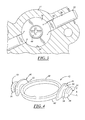
- FIG. 3 is a fragmentary sectional view of an air valve of the carburetor with a seal removed;
- FIG. 4 is a perspective view of a seal removed from the air valve
- FIG. 5 is a plan view of the seal
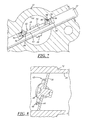
- FIG. 6 is a fragmentary sectional view of the air valve like FIG. 3 and showing the seal in place on the air valve;
- FIG. 7 is a fragmentary sectional view of the air valve showing the air valve in its fully open position.
- FIG. 8 is a fragmentary sectional view taken generally along line 8-8 in FIG. 6 .
- FIGS. 1 and 2 show a carburetor 10 that may be used to supply a fuel and air mixture to an engine to support combustion in the engine.
- the carburetor 10 as shown is a diaphragm type carburetor having a body 11 with a main bore 12 through which a fuel and air mixture is delivered to the engine and an air passage 14 through which air is supplied to the engine.
- the air supplied to the engine from the air passage 14 may be used to scavenge or help remove exhaust gasses from the engine.
- the flow of the fuel and air mixture through the main bore 12 may be controlled, at least in part, by a throttle valve 16.
- the flow of air through the air passage 14 may be controlled, at least in part, by an air valve 18.
- This type of carburetor 10 may be referred to as a stratified scavenging carburetor, or an air scavenging carburetor.
- the carburetor 10 may be constructed and may operate as disclosed in USPN 6,896,245 issued on May 24, 2005 , the disclosure of which is incorporated herein by reference in its entirety.
- the throttle valve 16 may include an actuating lever 20 coupled to a throttle valve shaft 22 to rotate the throttle valve shaft 22, and a throttle valve head 26 (presented in dashed lines in FIG. 1 ) may be carried on the valve shaft 22 and within the main bore 12.
- the throttle valve shaft 22 may be rotatably received in a bore that intersects the main bore 12.
- the throttle valve head 26, in the implementation shown, is a thin disc or butterfly-type valve head.
- the valve head 26 may be rotated from a first position closing or substantially closing the main bore 12 (e.g. as shown in FIG. 2 ) to a second position wherein the valve head 26 may be fully opened.
- the valve head when in its second position may be parallel, or nearly parallel, to fluid flow through the main bore.
- the throttle valve 16 could be of a different type and construction, as desired.
- the throttle valve 16 could be a rotary throttle valve such as is shown in USPN 6,394,425 or a different type of valve.
- the air valve 18 is constructed similarly to the throttle valve 16.
- the air valve 18 may have an actuating lever 30 coupled to an air valve shaft 32 to rotate the air valve shaft 32, and an air valve head 34 may be carried on the air valve shaft 32 and at least partially within the air passage 14.
- the air valve shaft 32 may be rotatably received in a bore 36 that intersects the air passage 14.
- the air valve head 34 in the implementation shown, is a thin disc or butterfly-type valve head.
- the air valve head 34 may be rotated from a first position closing or substantially closing the air passage (e.g. as shown in FIGS. 6 and 8 ) to a second position wherein the air valve head may be fully opened (in at least some implementations, the air valve head when in its second position may be parallel, or nearly parallel, to fluid flow through the air passage as generally shown in FIG. 7 ).
- the air valve shaft 32 may be generally cylindrical and include a flat section 38 extending in the area of the air passage 14.
- the flat, thin, disc-shaped air valve head 34 may be connected to the flat section 38 of the air valve shaft 32, such as by a screw 40, adhesive, weld or other connector or connection feature.
- the air valve head 34 in at least some implementations, may be sized to fully or at least substantially close the air passage 14. Accordingly, when the air valve 18 is in its first position, as shown in FIG. 3 , the air valve fully or substantially prevents air flow through the air passage 14. This substantially limits or prevents the flow of air through the air passage 14 and to the engine to avoid leaning out the fuel and air mixture delivered to the engine during certain engine operating conditions, such as engine starting or idle engine operation.
- air may leak or otherwise flow past the air valve 18 and through the air passage 14.
- air may leak through the air passage 14 and to the engine even when the air valve 18 is in its first position.
- At least certain engines require very low flow rates of air and fuel to support idle operation of the engine. In these engines, extra air flow through the air passage 14 may adversely affect engine operation and/or require the throttle valve 16 to have to be closed more for engine idle operation which can affect acceleration, idle stability (e.g. rollout) and come down performance of the engine.
- one or more seals 42 may be provided for the air valve 18, to seal the junction points X between the air valve shaft 32, air valve head 34 and the air passage 14.
- the seal 42 may be a single, unitary body with all of its features and components formed from the same piece of material. Of course, separate seals could be used for the various junction points X.
- the seal 42 may have a flat first face 44 adapted to be received against a face of the air valve head 34.
- the seal 42 may include two opposed sealing members 46 interconnected by an intermediate portion 48.
- the sealing members 46 are spaced apart and are adapted to be located at diametrically opposed sides of the air valve head 34 to cover the generally diametrically opposed junctions X of the air valve head 34 and air valve shaft 32.
- the sealing members 46 preferably have an outer surface 50 adapted to engage the carburetor body 11 within the air passage 14 at one or more, and up to all, of the junction points X.
- the outer surfaces 50 may be spaced apart a distance equal to or greater than the diameter of the air passage 14 so that each outer surface 50 engages and seals against the carburetor body 11 to limit or prevent airflow therebetween.
- the outer surfaces 50 may be curved or arcuate and complementary in shape to the air passage 14, or at least somewhat conformable to the shape of the air passage 14.
- the sealing members 46 may more effectively seal or block the junction points X and accommodate variations in the size and shape of the air valve head 34, air valve shaft 32 and air passage 14.
- the sealing members 46 may have a height h ( FIG. 4 ) (dimension extending away from the first face 44) and a length 1 ( FIG. 5 ) sufficient to fully cover the portion of the bore 36 for the air valve shaft 32 that is left open to the air passage 14 due to the flat section 38 formed in the air valve shaft 32. That is, the height h of the sealing members 46 may, if desired, be equal to or greater than the maximum distance from the air valve head 34 to the opposite surface of the bore 36 for the air valve shaft 32. And the length 1 may be greater than the diameter of the bore 36 for the air valve shaft 32. In this way, the sealing members 46 may be maintained within the air passage 14 and at least substantially out of the bore 36 of the air valve shaft 32, if desired.
- the seal 42 may also include one or more retention features 54, which are shown in this implementation as being located outboard of the sealing members 46. In the implementation shown, one retention feature 54 is provided outboard of each sealing member 46, providing two generally diametrically opposed retention features 54.
- Each retention feature 54 may include a knob 56 adapted to be at least partially received within the bore 36 for the air valve shaft 32.
- the retention features or knobs 56 may have a height (dimension extending away from the first face) that is slightly less than, equal to or greater than the distance from the air valve shaft 32 (and/or valve head 34) to a surface of the bore 36 of the air valve shaft 32 to maintain the seal 42 generally flat against the air valve head 34.
- the knobs 56 may be closely received in the bore 36 but with some gap between the knob and bore, or the knobs may have an interference fit within the bore. Accordingly, in this implementation, the seal 42 may be retained in place relative to the valve head 34 and air passage 14 without a connection feature, such as a fastener or adhesive, connecting the seal 42 to the valve head 34. This facilitates relative movement between the seal 42 and valve head 34 which may facilitate rotation of the valve head and re-establishing a seal at the junction points X when the air valve is closed again, as will be explained in more detail below.
- a reduced thickness web 58 may interconnect the knobs 56 to their adjacent sealing members 46 to improve the flexibility of the sealing members 46.
- the retention features 54 could be formed from the same piece of material as the sealing members 46, as is shown, or they could be separately formed and connected to the sealing members.
- the seal 42 may include an intermediate portion 48.
- the intermediate portion 48 may extend between and interconnect the sealing members 46, and the intermediate portion 48 may be received within the air passage 14 and generally against the air valve head 34, if desired.
- a reduced thickness and/or reduced width connecting portion 59 may be provided between the intermediate portion 48 and the sealing members 46.
- the intermediate portion 48 may be generally flexible and resilient, and may provide a force that yieldably biases the sealing members 46 radially outwardly into engagement with the body 11 of the carburetor 10 within the air passage 14 at least when the sealing members 46 are displaced or flexed more toward each other than they are in the at rest or uninstalled position of the seal 42.
- the intermediate portion 48 is thin and generally annular and in assembly, surrounds the screw 40 holding the air valve head 34 to the air valve shaft 32.
- the intermediate portion 48 could be differently shaped and arranged, including a solid member, a straight strip of material, a spring or other, as desired.
- the intermediate portion 48 could be formed from the same piece of material as the sealing members 46 and retention features 54, as is shown, or it could be a different piece of material coupled to the sealing members. Further, more than one intermediate portion 48 could be used.
- an indicator 60 may be provided on the seal 42. As shown, the indicator 60 includes a protrusion on the intermediate portion 48 which provides a visual indicator of the position of the seal 42 during and after installation of the seal.
- the distance between the points of engagement of the sealing members 46 and the body 11 changes as the air valve 18 is rotated between its first and second positions. As shown in FIG. 7 , when the air valve 18 is rotated to its second position, the distance between the points of engagement of the sealing members 46 and the carburetor body 11 is less than when the air valve 18 is in its first position, as shown in FIG. 3 . Accordingly, as the air valve 18 is rotated, at least a portion of the sealing members 46 are deflected or displaced inwardly, toward each other. This movement may be accommodated by flexing of the intermediate portion 48, by flexing of the sealing members 46, or both.
- the sealing members 46 may be curved and the outer surfaces 50 may be generally convex and opposite inner surfaces 51 may be generally convex, if desired.
- the intermediate member which separates and yieldably biases the sealing members outwardly, away from each other and the retention members which are maintained within the bore help to retain the seal in position within the air passage and adjacent to the air valve without the need for any physical or other connection between the air valve and the seal. This can facilitate assembly of the seal relative to the air valve and also readily accommodate flexing or deformation of the seal that may occur as the air valve is moved between its first and second positions.
- the seal 42 may be formed from any suitable material capable of providing the seal at the junction points X, durable enough for a high number of cycles, and having sufficient resiliency to return to its sealing position (as generally shown in FIG. 3 ) over a high number of cycles.
- Various polymers may be used, such as acetals like DELRIN which is suitable for use with and exposure to many liquid fuels. Of course, other materials may also be used.
- the seal 42 may also be used in other applications.
- the seal 42 could also be used with a throttle valve in an air throttle body such as may be used with fuel injected engine systems.
- the seal could limit or prevent air leakage through the junction points or areas between the throttle valve head, throttle valve shaft and throttle bore.
- the reduced or eliminated air leakage may make it easier to calibrate the throttle valve, and/or make calibration more accurate as the size of the leak paths at the junction points will vary from one throttle body to the next due to production tolerances and variations.
- the seal may make measuring and controlling airflow through a valve more consistent, reliable and easier by eliminating a source of air or fluid flow that is inconsistent and difficult to measure or determine apart from other air flow paths around or through the valve.
Landscapes
- Engineering & Computer Science (AREA)
- General Engineering & Computer Science (AREA)
- Mechanical Engineering (AREA)
- Chemical & Material Sciences (AREA)
- Combustion & Propulsion (AREA)
- Lift Valve (AREA)
Applications Claiming Priority (1)
| Application Number | Priority Date | Filing Date | Title |
|---|---|---|---|
| US13/230,894 US20130062547A1 (en) | 2011-09-13 | 2011-09-13 | Air valve sealing plug |
Publications (1)
| Publication Number | Publication Date |
|---|---|
| EP2570643A1 true EP2570643A1 (fr) | 2013-03-20 |
Family
ID=46750216
Family Applications (1)
| Application Number | Title | Priority Date | Filing Date |
|---|---|---|---|
| EP12180719A Withdrawn EP2570643A1 (fr) | 2011-09-13 | 2012-08-16 | Bouchon de fermeture de soupape d'air |
Country Status (3)
| Country | Link |
|---|---|
| US (1) | US20130062547A1 (fr) |
| EP (1) | EP2570643A1 (fr) |
| CN (1) | CN102996833A (fr) |
Families Citing this family (1)
| Publication number | Priority date | Publication date | Assignee | Title |
|---|---|---|---|---|
| CN110107701A (zh) * | 2019-06-19 | 2019-08-09 | 太仓源凯汽车配件有限公司 | 一种进气旁通阀的分段式阀头 |
Citations (3)
| Publication number | Priority date | Publication date | Assignee | Title |
|---|---|---|---|---|
| US3526385A (en) * | 1968-02-19 | 1970-09-01 | Varian Associates | O-ring with integral stem sealing means and butterfly valve using same |
| DE10237864A1 (de) * | 2002-08-19 | 2004-03-04 | Siemens Ag | Verfahren zum Abschliessen eines Drosselklappenstutzens |
| US6896245B2 (en) * | 2002-11-27 | 2005-05-24 | Walbro Japan, Inc. | Stratified scavenging carburetor |
Family Cites Families (5)
| Publication number | Priority date | Publication date | Assignee | Title |
|---|---|---|---|---|
| US3778028A (en) * | 1972-08-02 | 1973-12-11 | Dore Co John L | Lined butterfly valve |
| US3902697A (en) * | 1973-09-27 | 1975-09-02 | Milwaukee Valve | Butterfly valve |
| US3961405A (en) * | 1973-09-27 | 1976-06-08 | Milwaukee Valve Company, Inc. | Method of fabricating a butterfly valve |
| CH641259A5 (de) * | 1979-10-09 | 1984-02-15 | Fischer Ag Georg | Absperrklappe. |
| US4304392A (en) * | 1980-03-10 | 1981-12-08 | Crane Co. | Sealing means |
-
2011
- 2011-09-13 US US13/230,894 patent/US20130062547A1/en not_active Abandoned
-
2012
- 2012-08-16 EP EP12180719A patent/EP2570643A1/fr not_active Withdrawn
- 2012-09-12 CN CN2012103355853A patent/CN102996833A/zh active Pending
Patent Citations (3)
| Publication number | Priority date | Publication date | Assignee | Title |
|---|---|---|---|---|
| US3526385A (en) * | 1968-02-19 | 1970-09-01 | Varian Associates | O-ring with integral stem sealing means and butterfly valve using same |
| DE10237864A1 (de) * | 2002-08-19 | 2004-03-04 | Siemens Ag | Verfahren zum Abschliessen eines Drosselklappenstutzens |
| US6896245B2 (en) * | 2002-11-27 | 2005-05-24 | Walbro Japan, Inc. | Stratified scavenging carburetor |
Also Published As
| Publication number | Publication date |
|---|---|
| US20130062547A1 (en) | 2013-03-14 |
| CN102996833A (zh) | 2013-03-27 |
Similar Documents
| Publication | Publication Date | Title |
|---|---|---|
| US7895989B2 (en) | Butterfly-type throttle valve | |
| US7395818B2 (en) | Multi-gaseous fuel control device for a combustion engine with a carburetor | |
| JPH04308332A (ja) | スロットル弁 | |
| US20090020099A1 (en) | Butterfly valve type throttle valve of internal combustion engine | |
| JP6544114B2 (ja) | 逆止弁装置及び蒸発燃料供給システム | |
| ATE133756T1 (de) | Zusammenbau eines vergasers für eine gasbrennkraftmaschine | |
| US20130062547A1 (en) | Air valve sealing plug | |
| JP2017223292A (ja) | 流量制御弁 | |
| JP2003343288A (ja) | 2サイクル掃気エンジン用気化器 | |
| EP0440474A1 (fr) | Carburateur à valve basculante pour systèmes à carburant gazeux | |
| US6920864B1 (en) | Throttle body | |
| US7267327B2 (en) | Throttle valve assembly and dust seal for a carburetor | |
| US7427057B1 (en) | Control valve assembly of a carburetor and method of assembly | |
| US10415508B2 (en) | Charge forming device with air bleed control valve | |
| JP2004516424A (ja) | フラップ弁 | |
| ATE507379T1 (de) | Luftansaugvorrichtung für verbrennungsmotoren | |
| US20190145352A1 (en) | Fuel supply device with inlet valve | |
| JP2025503243A5 (fr) | ||
| JP4234121B2 (ja) | エンジン用吸気装置 | |
| JPS5836185B2 (ja) | 内燃機関の気化器 | |
| EP2354497A1 (fr) | Dispositif de fourniture d'air pour moteurs à combustion interne | |
| JP2018044464A (ja) | 吸気装置および制御弁 | |
| US20150096284A1 (en) | Egr valve with ring seal for zero flow | |
| JP2005256779A (ja) | 可変吸気装置 | |
| US20080224418A1 (en) | Rotary Valve Internal Combustion Engine and Seal Arrangement |
Legal Events
| Date | Code | Title | Description |
|---|---|---|---|
| PUAI | Public reference made under article 153(3) epc to a published international application that has entered the european phase |
Free format text: ORIGINAL CODE: 0009012 |
|
| AK | Designated contracting states |
Kind code of ref document: A1 Designated state(s): AL AT BE BG CH CY CZ DE DK EE ES FI FR GB GR HR HU IE IS IT LI LT LU LV MC MK MT NL NO PL PT RO RS SE SI SK SM TR |
|
| AX | Request for extension of the european patent |
Extension state: BA ME |
|
| STAA | Information on the status of an ep patent application or granted ep patent |
Free format text: STATUS: THE APPLICATION IS DEEMED TO BE WITHDRAWN |
|
| 18D | Application deemed to be withdrawn |
Effective date: 20130921 |