EP2570708A2 - Brandschutzmanschette, Verwendung dieser Brandschutzmanschette, Verfahren zum Anbringen einer Brandschutzmanschette und Deckendurchführung - Google Patents
Brandschutzmanschette, Verwendung dieser Brandschutzmanschette, Verfahren zum Anbringen einer Brandschutzmanschette und Deckendurchführung Download PDFInfo
- Publication number
- EP2570708A2 EP2570708A2 EP12181471A EP12181471A EP2570708A2 EP 2570708 A2 EP2570708 A2 EP 2570708A2 EP 12181471 A EP12181471 A EP 12181471A EP 12181471 A EP12181471 A EP 12181471A EP 2570708 A2 EP2570708 A2 EP 2570708A2
- Authority
- EP
- European Patent Office
- Prior art keywords
- fire protection
- fire
- sleeve
- ceiling
- opening
- Prior art date
- Legal status (The legal status is an assumption and is not a legal conclusion. Google has not performed a legal analysis and makes no representation as to the accuracy of the status listed.)
- Withdrawn
Links
Images

Classifications
-
- E—FIXED CONSTRUCTIONS
- E04—BUILDING
- E04B—GENERAL BUILDING CONSTRUCTIONS; WALLS, e.g. PARTITIONS; ROOFS; FLOORS; CEILINGS; INSULATION OR OTHER PROTECTION OF BUILDINGS
- E04B1/00—Constructions in general; Structures which are not restricted either to walls, e.g. partitions, or floors or ceilings or roofs
- E04B1/62—Insulation or other protection; Elements or use of specified material therefor
- E04B1/92—Protection against other undesired influences or dangers
- E04B1/94—Protection against other undesired influences or dangers against fire
- E04B1/941—Building elements specially adapted therefor
- E04B1/943—Building elements specially adapted therefor elongated
- E04B1/944—Building elements specially adapted therefor elongated covered with fire-proofing material
-
- F—MECHANICAL ENGINEERING; LIGHTING; HEATING; WEAPONS; BLASTING
- F16—ENGINEERING ELEMENTS AND UNITS; GENERAL MEASURES FOR PRODUCING AND MAINTAINING EFFECTIVE FUNCTIONING OF MACHINES OR INSTALLATIONS; THERMAL INSULATION IN GENERAL
- F16L—PIPES; JOINTS OR FITTINGS FOR PIPES; SUPPORTS FOR PIPES, CABLES OR PROTECTIVE TUBING; MEANS FOR THERMAL INSULATION IN GENERAL
- F16L5/00—Devices for use where pipes, cables or protective tubing pass through walls or partitions
- F16L5/02—Sealing
- F16L5/04—Sealing to form a firebreak device
-
- A—HUMAN NECESSITIES
- A62—LIFE-SAVING; FIRE-FIGHTING
- A62C—FIRE-FIGHTING
- A62C2/00—Fire prevention or containment
- A62C2/06—Physical fire-barriers
- A62C2/065—Physical fire-barriers having as the main closure device materials, whose characteristics undergo an irreversible change under high temperatures, e.g. intumescent
-
- E—FIXED CONSTRUCTIONS
- E04—BUILDING
- E04B—GENERAL BUILDING CONSTRUCTIONS; WALLS, e.g. PARTITIONS; ROOFS; FLOORS; CEILINGS; INSULATION OR OTHER PROTECTION OF BUILDINGS
- E04B1/00—Constructions in general; Structures which are not restricted either to walls, e.g. partitions, or floors or ceilings or roofs
- E04B1/62—Insulation or other protection; Elements or use of specified material therefor
- E04B1/92—Protection against other undesired influences or dangers
- E04B1/94—Protection against other undesired influences or dangers against fire
- E04B1/947—Protection against other undesired influences or dangers against fire by closing openings in walls or the like in the case of fire
-
- E—FIXED CONSTRUCTIONS
- E04—BUILDING
- E04B—GENERAL BUILDING CONSTRUCTIONS; WALLS, e.g. PARTITIONS; ROOFS; FLOORS; CEILINGS; INSULATION OR OTHER PROTECTION OF BUILDINGS
- E04B9/00—Ceilings; Construction of ceilings, e.g. false ceilings; Ceiling construction with regard to insulation
-
- H—ELECTRICITY
- H02—GENERATION; CONVERSION OR DISTRIBUTION OF ELECTRIC POWER
- H02G—INSTALLATION OF ELECTRIC CABLES OR LINES, OR OF COMBINED OPTICAL AND ELECTRIC CABLES OR LINES
- H02G3/00—Installations of electric cables or lines or protective tubing therefor in or on buildings, equivalent structures or vehicles
- H02G3/02—Details
- H02G3/04—Protective tubing or conduits, e.g. cable ladders or cable troughs
- H02G3/0406—Details thereof
- H02G3/0412—Heat or fire protective means
-
- H—ELECTRICITY
- H02—GENERATION; CONVERSION OR DISTRIBUTION OF ELECTRIC POWER
- H02G—INSTALLATION OF ELECTRIC CABLES OR LINES, OR OF COMBINED OPTICAL AND ELECTRIC CABLES OR LINES
- H02G3/00—Installations of electric cables or lines or protective tubing therefor in or on buildings, equivalent structures or vehicles
- H02G3/22—Installations of cables or lines through walls, floors or ceilings, e.g. into buildings
-
- Y—GENERAL TAGGING OF NEW TECHNOLOGICAL DEVELOPMENTS; GENERAL TAGGING OF CROSS-SECTIONAL TECHNOLOGIES SPANNING OVER SEVERAL SECTIONS OF THE IPC; TECHNICAL SUBJECTS COVERED BY FORMER USPC CROSS-REFERENCE ART COLLECTIONS [XRACs] AND DIGESTS
- Y10—TECHNICAL SUBJECTS COVERED BY FORMER USPC
- Y10T—TECHNICAL SUBJECTS COVERED BY FORMER US CLASSIFICATION
- Y10T428/00—Stock material or miscellaneous articles
- Y10T428/13—Hollow or container type article [e.g., tube, vase, etc.]
Definitions
- the invention relates to a fire protection sleeve and the use of such a fire protection sleeve. Moreover, the invention relates to a method for attaching a fire protection sleeve and a ceiling duct.
- Fire-resistant foreclosures of ceiling breakthroughs are preferably installed from above because of the lower workload and better accessibility.
- formworks are used for this purpose, which, if possible, are also installed from above. If this possibility is not given, e.g. classic wood formwork used, which must be mounted from the bottom of the ceiling breach ago.
- lost formwork which remain after closure of the breakthrough in this.
- mineral wool or construction foam can be used.
- the object of the present invention is to specify an improved fire protection collar and ceiling penetration as well as an improved method for attaching a fire protection collar, wherein the disadvantages known in the prior art should be overcome.
- a fire protection collar which includes fire protection additives and is designed as a rectangular strip.
- This rectangular strip may be provided along only one of its longitudinal sides with a plurality of cuts, so that adjacent tabs are formed.
- the cuts can be made transversely to a longitudinal direction of the rectangular strip. Thus arise transverse to the longitudinal direction oriented and adjacent in this direction tabs.
- Such a fire protection collar can advantageously be laid around an installation guided by a ceiling opening, for example around a plastic pipe or around a cable duct.
- the lugs present on one of their longitudinal sides can be bent transversely to the extension direction of the installation. If such a prepared fire protection collar is now inserted into the annular gap between the installation and the ceiling opening, the tabs are bent back onto the fire protection sleeve, and there is a pocket, which seals the annular gap on its underside.
- this bag can serve as a lost formwork for a scholar graduatesdes in the annular gap sealing material.
- Self-leveling sealants are preferably used as sealants for Deckenabschottung.
- the installation of the fire sleeve can be done only from above.
- the intumescent material of the fire sleeve is placed in the area of the pocket formed on the underside of the ceiling breach through the flaps of the fire sleeve, and thus near the entrance of the ceiling breakthrough so that it can react quickly.
- the fire protection sleeve according to The mentioned features is also very flexible. It can be adapted to different ceiling thicknesses, opening or breakthrough sizes, pipe sizes, etc.
- the fire protection collar is expediently at least partially made of a base material which comprises a matrix material and fire protection additives embedded therein.
- the matrix material serves as a binder for the fire protection additives.
- As the matrix material e.g. a polymer can be used.
- the proportion of the fire protection additives in the base material is advantageously from 10 to 90% by weight, preferably from 50 to 90% by weight, based on the base material. Accordingly, the proportion of the matrix material is 90 to 10 wt .-%, preferably 50 to 10 wt .-%, based on the base material. This ratio ensures the fire protection performance of the fire sleeve by providing a sufficient amount of fire protection additives that will provide the intumescence sufficient to close the ceiling breach.
- the fire sleeve can be tailored to the particular application.
- the fire sleeve can be completely made of the base material.
- the polymer used as the matrix material is preferably elastic, whereby the fire protection sleeve, even without the use of a carrier tape or a liner, the necessary mechanical properties can be imparted.
- fire protection additives those which act by the formation of a heat-generating, inflated, insulating layer of flame-retardant material (intumescent layer), which closes the ceiling duct and thereby prevents the passage of flames or at least delayed acting.
- a heat-generating, inflated, insulating layer of flame-retardant material intumescent layer
- Such systems are known to the person skilled in the art and can be used according to the invention.
- an intumescent layer by chemical means generally requires three components, a carbon source, a dehydrogenation catalyst and a blowing agent.
- the binder softens and the fire protection additives are released.
- Thermal decomposition releases the acid from the dehydrogenation catalyst, which removes water from the carbon source and / or the binder, causing it to char (carbonize) and thus form a charcoal structure so-called ash crust leads.
- the blowing agent thermally decomposes to form non-combustible gases which cause foaming of the carbonized (charred) material to form an insulating foam.
- a compound is preferably added to the components just listed which is capable of stabilizing the ash crust formed by the binder or even forming a scaffold, whereby the insulating effect of the coating is maintained or enhanced.
- Suitable dehydrogenation catalysts or acid formers are the compounds customarily used in intumescent flame retardants and known to the person skilled in the art, such as a salt or an ester of an inorganic, non-volatile acid selected from sulfuric acid, phosphoric acid or boric acid.
- phosphorus-containing compounds are used whose range is very large, as they extend over several oxidation states of the phosphorus, such as phosphines, phosphine oxides, phosphonium compounds, phosphates, elemental red phosphorus, phosphites and phosphates.
- the phosphoric acid compounds there can be exemplified monoammonium phosphate, diammonium phosphate, ammonium phosphate, ammonium polyphosphate, melamine phosphate, melamine resin phosphate, potassium phosphate, polyol phosphates such as pentaerythritol phosphate, glycerin phosphate, sorbitol phosphate, mannitol phosphate, dulcite phosphate, neopentyl glycol phosphate, ethylene glycol phosphate, dipentaerythritol phosphate and the like.
- the phosphoric acid compound used is preferably a polyphosphate or an ammonium polyphosphate.
- Under melamine resin phosphates are compounds such as reaction products of Lamelite C (melamine-formaldehyde resin) to understand with phosphoric acid.
- sulfuric acid compounds there may be exemplified ammonium sulfate, ammonium sulfamate, nitroaniline bisulfate, 4-nitroaniline-2-sulfonic acid and 4,4-dinitrosulfanilamide, and the like.
- boric acid compound melamine borate can be exemplified.
- Suitable carbon sources are the compounds customarily used in intumescent flame retardants and known to the person skilled in the art, such as starch-like compounds, for example starch and modified starch, and / or polyhydric alcohols, such as saccharides and polysaccharides and / or a thermoplastic or thermosetting polymeric resin binder, such as a phenolic resin, a urea resin, a polyurethane, polyvinyl chloride, poly (meth) acrylate , Polyvinyl acetate, polyvinyl alcohol, a silicone resin and / or a rubber.
- starch-like compounds for example starch and modified starch
- polyhydric alcohols such as saccharides and polysaccharides and / or a thermoplastic or thermosetting polymeric resin binder, such as a phenolic resin, a urea resin, a polyurethane, polyvinyl chloride, poly (meth) acrylate , Polyvinyl acetate, polyvinyl alcohol,
- Suitable polyols are polyols from the group consisting of sugar, pentaerythritol, dipentaerythritol, polyvinyl acetate, polyvinyl alcohol, sorbitol, ethylene oxide-propylene oxide polyols. Preference is given to using pentaerythritol, dipentaerythritol or polyvinyl acetate.
- the matrix material itself can also have the function of a carbon supplier in case of fire.
- Suitable blowing agents are the compounds conventionally used in flame retardants and known to those skilled in the art, such as cyanuric acid or isocyanic acid and its derivatives, melamine and derivatives thereof.
- cyanuric acid or isocyanic acid and its derivatives such as cyanuric acid or isocyanic acid and its derivatives, melamine and derivatives thereof.
- Such are cyanamide, dicyanamide, dicandiamide, guanidine and its salts, biguanide, melamine cyanurate, cyano acid salts, cyanic acid esters and amides, hexamethoxymethylmelamine, dimelamine pyrophosphate, melamine polyphosphate, melamine phosphate.
- Hexamethoxymethylmelamine or melamine (cyanuric acid amide) is preferably used.
- melamine polyphosphate which acts both as an acid generator and as a propellant.
- Other examples are in the GB 2 007 689 A1 .
- Suitable as ash crust stabilizers or scaffold formers are the compounds customarily used in flame retardants and known to the person skilled in the art, for example expandable graphite and particulate metals, such as aluminum, magnesium, iron and zinc.
- the particulate metal may be in the form of a powder, platelets, flakes, fibers, filaments and / or whiskers, wherein the particulate metal in the form of powder, platelets or flakes Particle size of ⁇ 50 microns, preferably from 0.5 to 10 microns has.
- a thickness of 0.5 to 10 ⁇ m and a length of 10 to 50 ⁇ m are preferred.
- an oxide or a compound of a metal from the group comprising aluminum, magnesium, iron or zinc may be used, in particular iron oxide, preferably iron trioxide, titanium dioxide, a borate, such as zinc borate and / or a glass frit of low-melting glasses a melting temperature of preferably at or above 400 ° C.
- iron oxide preferably iron trioxide, titanium dioxide, a borate, such as zinc borate and / or a glass frit of low-melting glasses a melting temperature of preferably at or above 400 ° C.
- the addition of such an ash crust stabilizer contributes to a substantial stabilization of the intumescent crust in case of fire, since these additives increase the mechanical strength of the intumescent layer and / or prevent it from dripping off. Examples of such additives can also be found in US 4 442 157 A . US 3 562 197 A . GB 755 551 A such as EP 138 546 A1 ,
- ash crust stabilizers such as melamine phosphate or melamine borate and ablative compounds, ie those which decompose endothermically, such as compounds containing water of crystallization, e.g. Aluminum trihydroxide, be included.
- the fire protection sleeve in addition to the base material comprises a carrier tape.
- This can be flexible, so that the fire protection sleeve by this carrier tape not only a certain strength, but at the same time also given a certain elasticity.
- the size of the carrier tape is selected congruent to the rectangular strip. The tabs of such a fire sleeve creep into the ceiling opening when the fire sleeve is inserted from above into the annular gap, and reliably form a pocket.
- the fire protection sleeve with carrier tape expediently consists of at least 30%, preferably up to 75%, of base material.
- the carrier tape is coated on one or both sides with base material.
- the carrier tape is thus embedded as an insert in the base material.
- the advantageously flexible carrier tape consists for example of a fabric, fleece and / or a sheet. Also wire-backed fabric or fleece can be used as carrier tape.
- a fleece also has the advantage that the fire sleeve simultaneously causes a structure-borne sound decoupling. To improve this effect, the fire protection sleeve, or its carrier tape, additional with a compressible layer, for example made of sponge rubber, can be provided.
- the incisions made in the rectangular strips can preferably be spaced apart between 2 mm and 30 mm in a longitudinal direction of the fire protection sleeve. Such a distance has proven to be a good compromise between flexibility and stability of the flaps of the fire sleeve.
- the fire sleeve is used according to one or more of the aforementioned features as a permanent formwork for a ceiling breakthrough. So can be dispensed with an additional formwork, which means a reduced installation costs and a cost advantage.
- a ceiling duct is provided with an opening through which a pipe extends in the vertical direction.
- the tube may be surrounded by a fire sleeve.
- the lower edge of the fire sleeve may be provided with a plurality of bent tabs, which are supported on the wall of the opening.
- an additional fire protection material may be arranged in an area between the fire protection collar and the wall of the opening.
- a sealing material can be arranged between the tabs and the fire sleeve.
- the ceiling duct on a fire protection sleeve whose width is greater than the vertical length of the opening.
- the fire sleeve extends along the full length of the opening and this is fire protection reliable secured.
- a measured transversely to the longitudinal direction of the fire protection sleeve length of the tabs can be greater than the width of one between the Outside of the tube and the inside of the opening existing annular gap. This dimensioning of the tabs ensures that they bend back in the direction of the fire sleeve when inserting the fire sleeve in the annular gap, thus creating a bag that can be used as a lost formwork.
- a method for attaching a fire protection sleeve in a ceiling duct of a pipe is provided.
- the fire sleeve can be placed around the pipe and above the ceiling.
- a ceiling facing the ceiling of the fire sleeve can be provided with several tabs.
- the fire sleeve is placed around the pipe with its tabs facing the aperture through which the pipe passes.
- the tabs of the fire protection collar can be bent transversely to an extension direction of the tube.
- the fire sleeve can be inserted into an existing between a wall of the opening and an outer side of the pipe annular gap in the ceiling, whereby the tabs of the fire sleeve are bent back.
- a pocket is created within the opening into which a sealing material can be introduced.
- conventional backfill materials such as e.g. Mortar, plaster, fire protection foam or mineral wool can be used.
- FIG. 1 is a simplified sectional view showing a tube 4 passed through a ceiling aperture 2.
- a wiring harness, a cable duct or another supply path, which uses combustible material may be passed through the ceiling opening 2.
- a fire protection collar 6 for protection against fire protection, there is a fire protection collar 6 in an annular gap 8 which extends between an outside of the pipe 4 and an inside of the opening 2 present in the ceiling 10.
- the fire protection sleeve 6 is band-shaped and is at least simply wrapped around the tube 4.
- the fire protection sleeve 6 includes conventional and known in the art fire protection additives, such as heat expandable materials such as expanded graphite, acid formers such as ammonium polyphosphate, carbon sources such as sugar polyols (eg pentaerythritol), gas generators (blowing agents), such as cyanuric acid derivatives, and ablative, ie endothermic decomposable compounds, like aluminum trihydroxide.
- fire protection sleeve 6 can be wrapped around the tube 4 several times. The number of windings can be adapted to the specific application, wherein the pipe diameter, the pipe material, a radial extent R of the annular gap 8, the ceiling thickness D and the positioning of the fire protection sleeve 6 can be considered.
- the fire protection sleeve 6 is inserted into the annular gap 8 from the upper side 12 of the ceiling 10.
- the tabs 14 present in the lower region of the fire protection sleeve 6 are bent in the direction of the fire protection sleeve 6 so that a pocket 16 is formed in the lower part of the annular gap 8.
- the fire sleeve 6 may simultaneously be used as permanent formwork for a sealing material to be inserted into the annular gap 8 from the top 12 of the blanket 10, e.g. a flowable mortar, to be used.
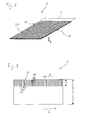
- FIG. 2 shows a simplified perspective view of a fire sleeve 6 before 18 incisions were made along one of its longitudinal sides.
- the fire protection sleeve 6 consists of a base material, which consists of a Matrix material and embedded therein fire protection additives.
- This base material may be a polymer such as polyurethane, acrylate, silicone, EPDM, etc.
- the fire protection additives can be the fire protection additives known to the person skilled in the art.
- the base material of the fire protection sleeve 6 is reinforced with a carrier tape 20, which in FIG. 2 is shown as a structured surface.
- This preferably flexible carrier tape 20 may consist of a woven fabric, a wire-reinforced fabric or fleece or also of a flexible sheet metal.
- the carrier tape 20 reinforces the fire protection sleeve 6, so that their tabs 14 reliably clamp in the annular gap 8 (see also FIG. 1 ).
- the carrier tape 20 may be non-combustible. If, for example, a non-flammable fabric layer is used as the carrier tape 20, then as a result improved ashes crust stability can positively influence the behavior of the fire protection sleeve 6 in the event of fire.
- a carrier tape 20 is not necessary for a fire protection sleeve 6 according to one embodiment.
- This may consist exclusively of base material, for example of a polymer or a polymer mixture with embedded fire protection additives.
- the carrier tape 20 used to support the base material can - in the assembled state of the fire protection sleeve 6 - be arranged both tube side and the pipe 4 away.
- Another possibility is to coat the carrier tape 20 on both sides with base material, so that the carrier tape 20 is embedded in the base material.
- its overall thickness B should not exceed 5 mm.
- the width S of the fire protection sleeve 6 is preferably matched to the thickness D of the ceiling 10, in which the opening 2 is located.
- the tube 4 can be secured along the entire length of the opening 2.
- the width S is also to be chosen so large that in addition sufficiently long tabs 14 for forming the bag 16 are present (see also FIG. 1 ).
- the fire protection sleeve 6 should consist predominantly of base material and the carrier tape 20 should only play a minor role. In empirical investigations it has been found that it is advantageous if the base material occupies at least 30%, preferably 75% of the fire protection sleeve 6.
- FIG. 3 shows a fire sleeve 6 according to another embodiment.
- cuts 22 are already introduced into a longitudinal side 18.
- the incisions 22 are spaced apart in a longitudinal direction L of the fire protection sleeve 6 by a cutting distance X from each other.
- the cutting distance X is preferably between 2 mm and 30 mm. It determines the width of the tabs 14 formed between the cuts 22.
- the mentioned cutting distance X has proved to be a good compromise in order to obtain both stable and flexible tabs 14.
- the width S of the fire protection sleeve 6 is determined by the thickness D of the ceiling 10
- a cutting depth Y is determined by the radial width R of the annular gap 8.
- the incision depth Y is preferably chosen to be greater than the radial width R of the annular gap 8, so that the desired pockets 16 at the lower end of the opening result by bending over the tabs 14 (cf. FIG. 1 ).
- the following dimensions of the fire protection sleeve 6 have proven to be advantageous: tube type Pipe diameter Annular gap R Bandwidth S Strip thickness B Intumescence volume under load windings up to max. [mm] up to max. [mm] [Mm] [Mm] N-tuple number metal pipes 400 100 300 2 10 > 2 Plastic pipes 160 50 250 4 10 2-4
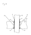
- FIG. 4 shows a further simplified sectional view of a tube 4, which is protected by means of a fire protection sleeve 6 and is guided by an existing in a ceiling 10 opening 2.
- the tabs 14 of the fire sleeve 6 have splayed in the opening 2 and form a pocket 16.
- a backfill material 24 is filled into the annular gap 8, in the exemplary embodiment shown it is mineral wool.
- a Sealant 26 sealed In the area of the surface 12 of the ceiling 10 of the opening 2 is also with a Sealant 26 sealed. This may preferably be a self-leveling sealant such as flowable mortar or gypsum.
- the fire protection collar 6 may be provided on at least one of its two flat sides with an additional compressible layer, e.g. made of sponge rubber, be provided.
- an additional compressible layer e.g. made of sponge rubber
- the fire protection sleeve 6 allows easy installation from the top 12 of the ceiling 10 ago. This allows a quick and inexpensive installation.
- the combination of lost formwork and fire protection sleeve 6 can be dispensed with an additional formwork, which allows a very economical installation. Due to the concentrated positioning of the fire protection cuff contained in the fire protection 6 a reliable and secure foreclosure can be ensured in particular at the bottom of the opening 2.
- the fire protection sleeve 6 according to the features mentioned can be provided as an endless roll material and therefore be used flexibly for different tubes 4 of different diameters. In addition, the insulation of the side facing away from the fire is possible with sufficient roll width S of the fire sleeve 6 for metal pipes or pipe cables in one operation.
Landscapes
- Engineering & Computer Science (AREA)
- Architecture (AREA)
- Civil Engineering (AREA)
- Structural Engineering (AREA)
- General Engineering & Computer Science (AREA)
- Physics & Mathematics (AREA)
- Electromagnetism (AREA)
- Mechanical Engineering (AREA)
- Health & Medical Sciences (AREA)
- Public Health (AREA)
- Business, Economics & Management (AREA)
- Emergency Management (AREA)
- Building Environments (AREA)
Abstract
Description
- Die Erfindung betrifft eine Brandschutzmanschette sowie die Verwendung einer solchen Brandschutzmanschette. Außerdem betrifft die Erfindung ein Verfahren zum Anbringen einer Brandschutzmanschette und eine Deckendurchführung.
- Brandsichere Abschottungen von Deckendurchbrüchen werden wegen des geringeren Arbeitsaufwandes und der besseren Erreichbarkeit bevorzugt von oben her installiert. In den meisten Fällen werden zu diesem Zweck Schalungen eingesetzt, welche, sofern möglich, ebenfalls von oben installiert werden. Ist diese Möglichkeit nicht gegeben, so werden z.B. klassische Holzschalungen verwendet, die von der Unterseite des Deckendurchbruchs her angebracht werden müssen. Für eine Installation von oben eignen sich insbesondere verlorene Schalungen, die nach Verschluss des Durchbruchs in diesem verbleiben. Zu diesem Zweck kann z.B. Mineralwolle oder Bauschaum verwendet werden.
- Zur brandtechnischen Absicherung von Installationen aus nicht brandresistenten Materialien, die durch den Deckendurchbruch geführt sind, muss mit Materialien gearbeitet werden, die im Brandfall den Deckendruchbruch verschließen. Dies kann durch den Einsatz von bestimmten Brandschutzadditiven erreicht werden, etwa solchen die unter Einwirkung von Hitze, wie bei einem Brand, eine Intumeszenz hervorrufen. Unter Verwendung von Mineralwolle hergestellte verlorene Schalungen weisen jedoch aufgrund der Dämmeigenschaften der Mineralwolle den Nachteil auf, dass sie auch das hinter der Mineralwolle liegende intumeszierende Material gegenüber der Hitze des Brandes isolieren. So kann dieses lediglich verzögert reagieren. Eine brennbare verlorene Schalung, z.B. aus Bauschaum, wäre geeigneter, erfordert jedoch einen gewissen Montageraum in dem Deckendurchbruch, sodass das die Brandschutzadditive enthaltenden Materialien sehr weit und somit möglicherweise nicht stabil in der Öffnung sitzen.
- Aufgabe der vorliegenden Erfindung ist es, eine verbesserte Brandschutzmanschette und Deckendurchführung sowie ein verbessertes Verfahren zum Anbringen einer Brandschutzmanschette anzugeben, wobei die im Stand der Technik bekannten Nachteile überwunden werden sollen.
- Gemäß einer ersten Ausführungsform wird eine Brandschutzmanschette angegeben, die Brandschutzadditive umfasst und als rechteckiger Streifen ausgeführt ist. Dieser rechteckige Streifen kann entlang nur einer seiner Längsseiten mit einer Vielzahl von Einschnitten versehen sein, sodass benachbarte Laschen gebildet werden. Vorteilhaft können die Einschnitte quer zu einer Längserstreckungsrichtung des rechteckigen Streifens ausgeführt werden. So entstehen quer zu der Längserstreckungsrichtung orientierte und in dieser Richtung benachbarte Laschen.
- Vorteilhaft kann eine solche Brandschutzmanschette um eine durch einen Deckendurchbruch geführte Installation, z.B. um ein Kunststoffrohr oder um einen Kabelkanal, gelegt werden. Die an einer ihrer Längsseiten vorhandenen Laschen können quer zur Erstreckungsrichtung der Installation abgebogen werden. Wird eine so vorbereitete Brandschutzmanschette nun in den Ringspalt zwischen der Installation und dem Deckendurchbruch eingeführt, so werden die Laschen auf die Brandschutzmanschette zurückgebogen, und es entsteht eine Tasche, welche den Ringspalt an seiner Unterseite abdichtet. Vorteilhaft kann diese Tasche als verlorene Schalung für ein in den Ringspalt einzufüllendes Dichtmaterial dienen. Bevorzugt werden selbstnivellierende Dichtmassen als Dichtstoffe für die Deckenabschottung verwendet. Vorteilhaft kann die Installation der Brandschutzmanschette ausschließlich von oben erfolgen. Dies bedeutet einen geringeren Montageaufwand. Außerdem wird das intumeszierende Material der Brandschutzmanschette im Bereich der an der Unterseite des Deckendurchbruchs durch die Laschen der Brandschutzmanschette gebildeten Tasche und somit in der Nähe des Eingangs des Deckendurchbruchs platziert, sodass dieses schnell reagieren kann. Die Brandschutzmanschette gemäß den genannten Merkmalen ist außerdem sehr flexibel. Sie kann an unterschiedliche Deckenstärken, Öffnungs- bzw. Durchbruchgrößen, Rohrgrößen, etc. angepasst werden.
- Zweckmäßig besteht die Brandschutzmanschette zumindest teilweise aus einem Basismaterial, welches ein Matrixmaterial und darin eingebettete Brandschutzadditive umfasst. Das Matrixmaterial dient dabei als Bindemittel für die Brandschutzadditive. Als Matrixmaterial kann z.B. ein Polymer verwendet werden. Vorteilhaft beträgt der Anteil der Brandschutzadditive in dem Basismaterial 10 bis 90 Gew.-%, bevorzugt 50 bis 90 Gew.-%, bezogen auf das Basismaterial. Dementsprechend beträgt der Anteil des Matrixmaterials 90 bis 10 Gew.-%, bevorzugt 50 bis 10 Gew.-%, bezogen auf das Basismaterial. Dieses Verhältnis stellt die Brandschutzeigenschaft der Brandschutzmanschette sicher, indem eine ausreichend große Menge an Brandschutzadditiven bereitgestellt wird, die die zum Verschließen des Deckendurchbruchs ausreichende Intumeszenz hervorrufen. So kann die Brandschutzmanschette auf die jeweilige Anwendung abgestimmt werden. Die Brandschutzmanschette kann dabei vollständig aus dem Basismaterial bestehen. Das als Matrixmaterial verwendete Polymer ist vorzugsweise elastisch, wodurch der Brandschutzmanschette, auch ohne Verwendung eines Trägerbandes oder einer Einlage, die notwendigen mechanischen Eigenschaften verliehen werden können.
- Bevorzugt werden als Brandschutzadditive solche eingesetzt, die durch die Bildung einer sich unter Hitzeeinwirkung bildenden, aufgeblähten, isolierenden Schicht aus schwerentflammbaren Material (intumeszierende Schicht), die die Deckendurchführung verschließt und dadurch den Übertritt von Flammen verhindert oder zumindest verzögert, wirken. Solche Systeme sind dem Fachmann bekannt und können erfindungsgemäß eingesetzt werden.
- Für die Ausbildung einer intumeszierenden Schicht auf chemischem Weg sind allgemein drei Komponenten erforderlich, ein Kohlenstofflieferant, ein Dehydrierungskatalysator und ein Treibmittel. Bei Hitzeinwirkung erweicht das Bindemittel und die Brandschutzadditive werden freigesetzt. Durch thermische Zersetzung wird aus dem Dehydrierungskatalysator die Säure freigesetzt, die dem Kohlenstofflieferanten und/oder dem Bindemittel Wasser entziehen, was zu deren Verkohlung (Carbonisierung) und somit zur Bildung einer Kohlestruktur, der sogenannten Aschekruste führt. Gleichzeitig zersetzt sich das Treibmittel thermisch unter Bildung nicht-brennbarer Gase, die ein Aufschäumen des carbonisierten (verkohlten) Materials unter Bildung eines isolierenden Schaums bewirken. Da die im Brandfall durch das Bindemittel gebildete Aschekruste in der Regel zu instabil ist und abhängig von deren Dichte und Struktur etwa durch Luftströmungen verblasen werden kann, was sich negativ auf die isolierende Wirkung der Beschichtung auswirkt, wird zu den eben aufgeführten Komponenten bevorzugt eine Verbindung gegeben, die die durch das Bindemittel gebildete Aschekruste zu stabilisieren vermag oder selbst ein Gerüst bildet, wodurch die isolierende Wirkung der Beschichtung aufrechterhalten oder verstärkt wird.
- Als Dehydrierungskatalysatoren bzw. Säurebildner kommen die in intumeszierenden Flammschutzmitteln üblicherweise verwendeten und dem Fachmann bekannten Verbindungen, in Betracht, wie ein Salz oder ein Ester einer anorganischen, nicht flüchtigen Säure, ausgewählt unter Schwefelsäure, Phosphorsäure oder Borsäure. Im wesentlichen werden phosphorhaltige Verbindungen eingesetzt, deren Palette sehr groß ist, da sie sich über mehrere Oxidationsstufen des Phosphors erstrecken, wie Phosphine, Phosphinoxide, Phosphoniumverbindungen, Phosphate, elementarer roter Phosphor, Phosphite und Phosphate. Als Phosphorsäureverbindungen können beispielhaft erwähnt werden: Monoammoniumphosphat, Diammoniumphosphat, Ammoniumphosphat, Ammoniumpolyphosphat, Melaminphosphat, Melaminharzphosphate, Kaliumphosphat, Polyolphosphate wie etwa Pentaerythritphosphat, Glyzerinphosphat, Sorbitphosphat, Mannitphosphat, Dulcitphosphat, Neopentylglykolphosphat, Ethylenglykolphosphat, Dipentaerythritphosphat und dergleichen. Bevorzugt wird als Phosphorsäureverbindung ein Polyphosphat oder ein Ammoniumpolyphosphat eingesetzt. Unter Melaminharzphosphate sind dabei Verbindungen wie Umsetzungsprodukte aus Lamelite C (Melamin-Formaldehyd-Harz) mit Phosphorsäure zu verstehen. Als Schwefelsäureverbindungen können beispielhaft erwähnt werden: Ammoniumsulfat, Ammoniumsulfamat, Nitroanilinbisulfat, 4-Nitroaniline-2-sulfonsäure und 4,4-Dinitrosulfanilamid und dergleichen. Als Borsäureverbindung kann Melaminborat beispielhaft erwähnt werden.
- Als Kohlenstofflieferant kommen die in intumeszierenden Flammschutzmitteln üblicherweise verwendeten und dem Fachmann bekannten Verbindungen in Betracht, wie stärkeähnliche Verbindungen, z.B. Stärke und modifizierte Stärke, und/oder mehrwertige Alkohole (Polyole), wie Saccharide und Polysaccharide und/oder ein thermoplastisches oder duroplastisches polymeres Harzbindemittel, wie ein Phenolharz, ein Harnstoffharz, ein Polyurethan, Polyvinylchlorid, Poly(meth)acrylat, Polyvinylacetat, Polyvinylalkohol, ein Silikonharz und/oder einen Kautschuk.. Geeignete Polyole sind Polyole aus der Gruppe Zucker, Pentaerythrit, Dipentaerythrit, Polyvinylacetat, Polyvinylalkohol, Sorbitol, Ethylenoxid-Propylenoxid-Polyole. Bevorzugt werden Pentaerythrit, Dipentaerythrit oder Polyvinylacetat eingesetzt.
- Es sei erwähnt, dass das Matrixmaterial im Brandfall selbst auch die Funktion eines Kohlenstofflieferanten haben kann.
- Als Treibmittel kommen die üblicherweise in Flammschutzmitteln verwendeten und dem Fachmann bekannten Verbindungen in Betracht, wie Cyanursäure oder Isocyansäure und deren Derivate, Melamin und deren Derivate. Solche sind Cyanamid, Dicyanamid, Dicandiamid, Guanidin und dessen Salze, Biguanid, Melamincyanurat, Cyansäuresalze, Cyansäureester und -amide, Hexamethoxymethylmelamin, Dimelaminpyrophosphat, Melaminpolyphosphat, Melaminphosphat. Bevorzugt wird Hexamethoxymethylmelamin oder Melamin (Cyanursäureamid) eingesetzt.
- Geeignet sind ferner Komponenten, die ihre Wirkungsweise nicht auf eine einzige Funktion beschränkt, wie Melaminpolyphosphat, das sowohl als Säurebildner als auch als Treibmittel wirkt. Weitere Beispiele sind in der
GB 2 007 689 A1 EP 139 401 A1 US-3 969 291 A1 beschrieben. - Daneben können Verbindungen enthalten sein, die unter Hitze ohne die Einwirkung bzw. die Reaktion mit anderen Verbindungen von sich aus intumeszieren, wie Blähgraphit, Vermiculit (Blähglimmer) und dergleichen.
- Als Aschekrustenstabilisatoren bzw. Gerüstbildner kommen die üblicherweise in Flammschutzmitteln verwendeten und dem Fachmann bekannten Verbindungen in Betracht, beispielsweise Blähgraphit und teilchenförmige Metalle, wie Aluminium, Magnesium, Eisen und Zink. Das teilchenförmige Metall kann in Form eines Pulvers, von Plättchen, Schuppen, Fasern, Fäden und/oder Whiskers vorliegen, wobei das teilchenförmige Metall in Form von Pulver, Plättchen oder Schuppen eine Teilchengrösse von ≤50 µm, vorzugsweise von 0,5 bis 10 µm besitzt. Im Fall der Verwendung des teilchenförmigen Metalls in Form von Fasern, Fäden und/oder Whiskers ist eine Dicke von 0,5 bis 10 µm und eine Länge von 10 bis 50 µm bevorzugt. Als Aschekrustenstabilisator kann alternativ oder zusätzlich ein Oxid oder eine Verbindung eines Metalls aus der Aluminium, Magnesium, Eisen oder Zink umfassenden Gruppe eingesetzt werden, insbesondere Eisenoxid, vorzugsweise Eisentrioxid, Titandioxid, ein Borat, wie Zinkborat und/oder eine Glasfritte aus niedrig schmelzenden Gläsern mit einer Schmelztemperatur von vorzugsweise bei oder oberhalb 400°C. Die Zugabe eines solchen Aschekrustenstabilisators trägt zu einer wesentlichen Stabilisierung der Intumeszenzkruste im Brandfall bei, da diese Additive die mechanische Festigkeit der intumeszierenden Schicht erhöhen und/oder deren Abtropfen verhindern. Beispiele derartiger Additive finden sich auch in
US 4 442 157 A ,US 3 562 197 A ,GB 755 551 A EP 138 546 A1 - Daneben können Aschekrustenstabilisierer wie Melaminphosphat oder Melaminborat und ablative Verbindungen, also solche die sich endotherm Zerstzen, wie Kristallwasserhaltige Verbindungen, z.B. Aluminiumtrihydroxid, enthalten sein.
- In einer weiteren vorteilhaften Ausführungsform der Erfindung umfasst die Brandschutzmanschette zusätzlich zu dem Basismaterial ein Trägerband. Dieses kann flexibel sein, sodass der Brandschutzmanschette durch dieses Trägerband nicht nur eine gewisse Festigkeit, sondern gleichzeitig auch eine gewisse Elastizität verliehen wird. Vorteilhaft ist die Größe des Trägerbandes deckungsgleich zu dem rechteckigen Streifen gewählt. Die Laschen einer solchen Brandschutzmanschette verspreizen sich in dem Deckendurchbruch, wenn die Brandschutzmanschette von oben in den Ringspalt eingefügt wird, und bilden zuverlässig eine Tasche aus. Zweckmäßig besteht die Brandschutzmanschette mit Trägerband zumindest zu 30 %, bevorzugt zu bis zu 75 % aus Basismaterial. So kann auch bei Verwendung eines Trägerbandes ein hinreichend großes Intumeszenzvolumen sichergestellt werden, die Deckendurchführung im Brandfall zu verschließen.
- Bei einer weiteren Ausführungsform ist das Trägerband einseitig oder beidseitig mit Basismaterial beschichtet. Im letzten Fall ist das Trägerband also als Einlage in das Basismaterial eingebettet. Das vorteilhaft flexible Trägerband besteht z.B. aus einem Gewebe, Vlies und/oder einem Blech. Auch drahtunterstütztes Gewebe oder Vlies können als Trägerband verwendet werden. Ein Vlies hat außerdem den Vorteil, dass die Brandschutzmanschette gleichzeitig eine Körperschallentkopplung bewirkt. Zur Verbesserung dieses Effektes kann die Brandschutzmanschette, bzw. deren Trägerband, zusätzlichen mit einer komprimierbaren Schicht, z.B. aus Moosgummi, versehen werden.
- Die in den rechteckigen Streifen eingebrachten Einschnitte können in einer Längserstreckungsrichtung der Brandschutzmanschette bevorzugt zwischen 2 mm und 30 mm voneinander beabstandet sein. Ein solcher Abstand hat sich als guter Kompromiss zwischen Flexibilität und Stabilität der Laschen der Brandschutzmanschette herausgestellt.
- Vorteilhaft wird die Brandschutzmanschette gemäß einem oder mehreren der zuvor genannten Merkmale als verlorene Schalung für einen Deckendurchbruch verwendet. So kann auf eine zusätzliche Schalung verzichtet werden, was einen verringerten Montageaufwand und einen Kostenvorteil bedeutet.
- Gemäß einer weiteren Ausführungsform der Erfindung wird eine Deckendurchführung mit einer Öffnung, durch die sich ein Rohr in vertikaler Richtung erstreckt, angegeben. Das Rohr kann von einer Brandschutzmanschette umgeben sein. Der untere Rand der Brandschutzmanschette kann mit mehreren zurückgebogenen Laschen versehen sein, die sich an der Wandung der Öffnung abstützen. In einem Raum zwischen der Brandschutzmanschette und der Wandung der Öffnung kann ein zusätzliches Brandschutzmaterial angeordnet sein. Außerdem kann zwischen den Laschen und der Brandschutzmanschette ein Dichtmaterial angeordnet sein. Gleiche oder ähnliche Vorteile, die bereits im Hinblick auf die Brandschutzmanschette erwähnt wurden, treffen auch auf die genannte Deckendurchführung zu.
- Vorteilhaft weist die Deckendurchführung eine Brandschutzmanschette auf, deren Breite größer als die vertikale Länge der Öffnung ist. So erstreckt sich die Brandschutzmanschette entlang der vollständigen Länge der Öffnung und diese ist brandschutztechnisch zuverlässig abgesichert.
- Außerdem kann eine quer zur Längserstreckungsrichtung der Brandschutzmanschette gemessene Länge der Laschen größer sein als die Breite eines zwischen der Außenseite des Rohres und der Innenseite der Öffnung vorhandenen Ringspalts. Diese Dimensionierung der Laschen stellt sicher, dass sie sich beim Einführen der Brandschutzmanschette in den Ringspalt in Richtung der Brandschutzmanschette zurückbiegen und so eine Tasche entsteht, welche als verlorene Schalung verwendet werden kann.
- Gemäß einer weiteren Ausführungsform wird ein Verfahren zum Anbringen einer Brandschutzmanschette in einer Deckendurchführung eines Rohres angegeben. Die Brandschutzmanschette kann um das Rohr herum und oberhalb der Decke angeordnet werden. Ein der Decke zugewandter Rand der Brandschutzmanschette kann mit mehren Laschen versehen sein. Mit anderen Worten wird die Brandschutzmanschette so um das Rohr herum angeordnet, dass ihre Laschen in Richtung des Durchbruchs zeigen, durch den das Rohr geführt ist. Vorteilhaft können die Laschen der Brandschutzmanschette quer zu einer Erstreckungsrichtung des Rohres umgebogen werden. Schließlich kann die Brandschutzmanschette in einen zwischen einer Wandung der Öffnung und einer Außenseite des Rohrs vorhandenen Ringspalt in die Decke eingeschoben werden, wodurch die Laschen der Brandschutzmanschette zurückgebogen werden. Vorteilhaft entsteht auf diese Weise eine Tasche innerhalb der Öffnung, in welche ein Dichtmaterial eingeführt werden kann. Zu diesem Zweck können übliche Hinterfüllmaterialien wie z.B. Mörtel, Gips, Brandschutzschaum oder Mineralwolle verwendet werden.
- Im Folgenden wird die Erfindung unter Bezugnahme auf in den Zeichnungen gezeigte Ausführungsbeispiele näher erläutert. Dabei zeigt
- Fig. 1:
- eine vereinfachte Schnittansicht eines durch einen Deckendurchbruch geführten Rohrs, welches mit einer Brandschutzmanschette gemäß einem Ausführungsbeispiel abgesichert ist,
- Fig. 2:
- eine vereinfachte perspektivische Ansicht einer Brandschutzmanschette vor dem Einbringen der Einschnitte,
- Fig. 3:
- eine in Draufsicht dargestellte Brandschutzmanschette gemäß einem Ausführungsbeispiel, und
- Fig. 4:
- eine weitere vereinfachte Schnittansicht eines durch einen Deckendurchbruch geführten Rohrs nach Durchführung der Deckenabschottung.
-
Figur 1 ist eine vereinfachte Schnittansicht, welche ein durch einen Deckendurchbruch 2 geführtes Rohr 4 zeigt. Alternativ zu dem dargestellten Rohr 4 kann ein Leitungsstrang, ein Kabelkanal oder eine andere Versorgungsstrecke, die brennbares Material verwendet, durch den Deckendurchbruch 2 geführt sein. Zur brandschutztechnischen Absicherung befindet sich eine Brandschutzmanschette 6 in einem Ringspalt 8, der sich zwischen einer Außenseite des Rohres 4 und einer Innenseite des in der Decke 10 vorhandenen Durchbruchs 2 erstreckt. Die Brandschutzmanschette 6 ist bandförmig und wird zumindest einfach um das Rohr 4 herumgelegt. Die Brandschutzmanschette 6 umfasst übliche und dem Fachmann bekannte Brandschutzadditive, z.B. unter Hitzeeinwirkung expandierbare Materialien, wie Blähgraphit, Säurebildner, wie Ammoniumpolyphosphat, Kohlenstofflieferanten, wie Zuckerpolyole (z.B. Pentaerythrit), Gasbildner (Treibmittel), wie Cyanursäurederivate, und ablative, d.h. endotherm zersetzbare Verbindungen, wie Aluminiumtrihydroxid. Um zur brandschutztechnischen Absicherung des Durchbruchs 2 ein entsprechend großes Intumeszenzvolumen zur Verfügung zu stellen, kann die Brandschutzmanschette 6 mehrfach um das Rohr 4 herumgelegt sein. Die Anzahl der Wicklungen kann auf die spezielle Anwendung abgestimmt werden, wobei der Rohrdurchmesser, das Rohrmaterial, eine radiale Ausdehnung R des Ringspalts 8, die Deckenstärke D sowie die Positionierung der Brandschutzmanschette 6 in Betracht gezogen werden können. - Die Brandschutzmanschette 6 wird von der Oberseite 12 der Decke 10 her in den Ringspalt 8 eingeführt. Dabei werden die im unteren Bereich der Brandschutzmanschette 6 vorhandenen Laschen 14 in Richtung der Brandschutzmanschette 6 umgebogen, sodass sich im unteren Teil des Ringspaltes 8 eine Tasche 16 bildet. So kann die Brandschutzmanschette 6 gleichzeitig als verlorene Schalung für ein von der Oberseite 12 der Decke 10 her in den Ringspalt 8 einzuführendes Dichtmaterial, z.B. einen fließfähigen Mörtel, verwendet werden.
-
Figur 2 zeigt eine vereinfachte perspektivische Ansicht einer Brandschutzmanschette 6, bevor entlang einer ihrer Längsseiten 18 Einschnitte eingebracht wurden. Die Brandschutzmanschette 6 besteht aus einem Basismaterial, welches aus einem Matrixmaterial und darin eingebetteten Brandschutzadditiven besteht. Dieses Basismaterial kann ein Polymer wie beispielsweise Polyurethan, Acrylat, Silicon, EPDM, etc. sein. Bei den Brandschutzadditiven kann es sich um die dem Fachmann bekannten Brandschutzadditive handeln. Das Basismaterial der Brandschutzmanschette 6 ist mit einem Trägerband 20 verstärkt, welches inFigur 2 als strukturierte Oberfläche dargestellt ist. Dieses bevorzugt flexible Trägerband 20 kann aus einem Gewebe, einem drahtverstärkten Gewebe oder Vlies oder auch aus einem flexiblen Blech bestehen. Das Trägerband 20 verstärkt die Brandschutzmanschette 6, sodass sich deren Laschen 14 zuverlässig in dem Ringspalt 8 verspannen (vgl. auchFigur 1 ). Außerdem kann das Trägerband 20 nicht brennbar sein. Wird z.B. eine nicht brennbare Gewebelage als Trägerband 20 verwendet, so kann eine dadurch bedingt verbesserte Aschekrustenstabilität das Verhalten der Brandschutzmanschette 6 im Brandfall positiv beeinflussen. - Die Verwendung eines Trägerbandes 20 ist jedoch für eine Brandschutzmanschette 6 gemäß einem Ausführungsbeispiel keine notwendige Voraussetzung. Diese kann ausschließlich aus Basismaterial bestehen, z.B. aus einem Polymer oder einer Polymermischung mit darin eingebetteten Brandschutzadditiven. Das zur Unterstützung des Basismaterials verwendete Trägerband 20 kann - im montierten Zustand der Brandschutzmanschette 6 - sowohl rohrseitig als auch vom Rohr 4 abgewandt angeordnet sein. Eine weitere Möglichkeit besteht darin, das Trägerband 20 beidseitig mit Basismaterial zu beschichten, sodass das Trägerband 20 in dem Basismaterial eingebettet ist. Um eine problemlose Biegbarkeit der Brandschutzmanschette 6 sicherzustellen, sollte jedoch deren Gesamtstärke B 5 mm nicht überschreiten. Die Breite S der Brandschutzmanschette 6 wird bevorzugt auf die Dicke D der Decke 10 abgestimmt, in welcher sich der Durchbruch 2 befindet. So kann das Rohr 4 entlang der vollständigen Länge des Durchbruchs 2 abgesichert werden. Die Breite S ist außerdem so groß zu wählen, dass zusätzlich ausreichend lange Laschen 14 zur Ausbildung der Tasche 16 vorhanden sind (vgl. auch
Figur 1 ). - Um das gewünschte Intumeszenzvolumen zu erreichen, sollte die Brandschutzmanschette 6 jedoch überwiegend aus Basismaterial bestehen und das Trägerband 20 sollte lediglich eine untergeordnete Rolle spielen. In empirischen Untersuchungen hat sich herausgestellt, dass es vorteilhaft ist, wenn das Basismaterial zumindest 30 %, bevorzugt 75 % der Brandschutzmanschette 6 einnimmt.
-
Figur 3 zeigt eine Brandschutzmanschette 6 gemäß einem weiteren Ausführungsbeispiel. Bei dieser Brandschutzmanschette 6 sind bereits Einschnitte 22 in eine Längsseite 18 eingebracht. Die Einschnitte 22 sind in einer Längserstreckungsrichtung L der Brandschutzmanschette 6 um einen Schnittabstand X voneinander beabstandet. Bevorzugt liegt der Schnittabstand X zwischen 2 mm und 30 mm. Er bestimmt die Breite der zwischen den Einschnitten 22 entstehenden Laschen 14. Der genannte Schnittabstand X hat sich als guter Kompromiss herausgestellt, um sowohl stabile als auch flexible Laschen 14 zu erhalten. Während die Breite S der Brandschutzmanschette 6 durch die Dicke D der Decke 10 bestimmt ist, ist eine Einschnitttiefe Y durch die radiale Breite R des Ringspalts 8 bestimmt. Die Einschnitttiefe Y wird vorzugsweise größer gewählt als die radiale Breite R des Ringspalts 8, sodass sich durch Umbiegen der Laschen 14 die gewünschten Taschen 16 am unteren Ende des Durchbruchs ergeben (vgl. auchFigur 1 ). - Je nach Einsatzgebiet haben sich folgenden Dimensionierungen der Brandschutzmanschette 6 als vorteilhaft herausgestellt:
Rohrtyp Rohrdurchmesser Ringspalt R Bandbreite S Banddicke B Intumeszenzvolumen unter Last Wicklungen bis max [mm] bis max [mm] [mm] [mm] x-fach Anzahl Metallrohre 400 100 300 2 10 >2 Kunststoffrohre 160 50 250 4 10 2-4 -
Figur 4 zeigt eine weitere vereinfachte Schnittansicht eines Rohres 4, welches mithilfe einer Brandschutzmanschette 6 abgesichert ist und durch einen in einer Decke 10 vorhandenen Durchbruch 2 geführt ist. Die Laschen 14 der Brandschutzmanschette 6 haben sich in dem Durchbruch 2 verspreizt und bilden eine Tasche 16 aus. Zur Abschottung des Durchbruchs 2 wird in den Ringspalt 8 ein Hinterfüllmaterial 24 eingefüllt, bei dem gezeigten Ausführungsbeispiel handelt es sich um Mineralwolle. Im Bereich der Oberfläche 12 der Decke 10 ist der Durchbruch 2 außerdem mit einer Dichtmasse 26 versiegelt. Bei dieser kann es sich bevorzugt um eine selbstnivellierende Dichtmasse wie fließfähigen Mörtel oder Gips handeln. - Um eine Körperschalldämmung zwischen dem Rohr 4 und der Decke 10 herzustellen, kann die Brandschutzmanschette 6 auf zumindest einer ihrer beiden Flachseiten zusätzliche mit einer komprimierbaren Schicht, z.B. aus Moosgummi, versehen sein. Aus Gründen der einfachen Herstellbarkeit ist es vorteilhaft, das Trägerband 20 der Brandschutzmanschette 6 mit einer solchen komprimierbaren Schicht auf derjenigen Flachseite zu versehen, welche dem Basismaterial abgewandt ist.
- Die Brandschutzmanschette 6 gemäß den vorgenannten Ausführungsbeispielen erlaubt eine einfache Installation von der Oberseite 12 der Decke 10 her. So kann eine schnelle und kostengünstige Installation durchgeführt werden. Durch die Kombination aus verlorener Schalung und Brandschutzmanschette 6 kann auf eine zusätzliche Schalung verzichtet werden, was eine sehr wirtschaftliche Installation erlaubt. Aufgrund der konzentrierten Positionierung der in der Brandschutzmanschette 6 enthaltenen Brandschutzadditive kann eine zuverlässige und sichere Abschottung insbesondere an der Unterseite des Durchbruchs 2 gewährleistet werden. Die Brandschutzmanschette 6 gemäß den genannten Merkmalen kann als endloses Rollenmaterial zur Verfügung gestellt und daher flexibel für verschiedene Rohre 4 unterschiedlichen Durchmessers eingesetzt werden. Außerdem ist die Isolierung der feuerabgewandten Seite bei ausreichender Rollenbreite S der Brandschutzmanschette 6 für Metallrohre oder Rohrleiterkabel in einem Arbeitsgang möglich.
-
- 2
- Deckendurchbruch
- 4
- Rohr
- 6
- Brandschutzmanschette
- 8
- Ringspalt
- 10
- Decke
- 12
- Oberseite
- 14
- Lasche
- 16
- Tasche
- 18
- Längsseite
- R
- radiale Breite
- D
- Dicke
- 20
- Trägerband
- 22
- Einschnitte
- 24
- Dichtmasse
- 26
- weitere Dichtmasse
- B
- Gesamtstärke
- S
- Breite
- L
- Längserstreckungsrichtung
- X
- Schnittabstand
- Y
- Einschnitttiefe
Claims (18)
- Brandschutzmanschette, die Brandschutzadditive umfasst und als rechteckiger Streifen ausgeführt ist, der entlang nur einer Längsseite mit einer Vielzahl von Einschnitten versehen ist, sodass benachbarte Laschen gebildet sind.
- Brandschutzmanschette nach Anspruch 1, ein Trägerband umfassend.
- Brandschutzmanschette nach Anspruch 1 oder 2, die zumindest teilweise aus einem Basismaterial besteht, welches ein Matrixmaterial und darin eingebettete Brandschutzadditive umfasst.
- Brandschutzmanschette nach Anspruch 3, bei der das Basismaterial einen Anteil von 10 bis 90 Gew.-% an Brandschutzadditiven, bezogen auf das Basismaterial, enthält.
- Brandschutzmanschette nach Anspruch 3 oder 4, bei der der Anteil des Basismaterials an der Brandschutzmanschette mindestens 30 % beträgt.
- Brandschutzmanschette nach einem der Ansprüche 3 bis 5, bei der das Trägerband mit Basismaterial beschichtet ist.
- Brandschutzmanschette nach einem der Ansprüche 2 bis 6, bei der das Trägerband aus einem flexiblen Material besteht.
- Brandschutzmanschette nach Anspruch 7, bei der das Trägerband aus Gewebe und/oder aus Blech besteht.
- Brandschutzmanschette nach einem der vorhergehenden Ansprüche, bei der die Einschnitte in einer Längserstreckungsrichtung der Brandschutzmanschette zwischen 2 mm und 30 mm voneinander beabstandet sind.
- Verwendung einer Brandschutzmanschette nach einem der vorhergehenden Ansprüche als verlorene Schalung für einen Deckendurchbruch.
- Deckendurchführung mit einer Öffnung, durch die sich ein Rohr in vertikaler Richtung erstreckt, wobei das Rohr von einer Brandschutzmanschette nach einem der Ansprüche 1 bis 9 umgeben ist und deren unterer Rand mit mehreren zurückgebogenen Laschen versehen ist, die sich an der Wandung der Öffnung abstützen
- Deckendurchführung nach Anspruch 11, bei der zwischen der Brandschutzmanschette und der Wandung der Öffnung weiteres Brandschutzmaterial angeordnet ist.
- Deckendurchführung nach Anspruch 11 oder 12, bei der zwischen der Brandschutzmanschette und der Wandung der Öffnung ein Dichtmaterial angeordnet ist.
- Deckendurchführung Anspruch 11 bis 13, bei der die Brandschutzmanschette eine Breite aufweist, welche größer als die vertikale Länge der Öffnung ist.
- Deckendurchführung nach einem der Ansprüche 11 bis 14, bei der die Laschen der Brandschutzmanschette eine quer zu deren Längserstreckungsrichtung gemessene Länge haben, die größer ist als die Breite eines zwischen der Außenseite des Rohres und der Innenseite der Öffnung vorhandenen Ringspalts.
- Verfahren zum Anbringen einer Brandschutzmanschette in einer Deckendurchführung eines Rohres, bei dem die Brandschutzmanschette um das Rohr herum und oberhalb der Decke angeordnet wird, wobei ein der Decke zugewandter Rand der Brandschutzmanschette mit mehren Laschen versehen ist.
- Verfahren nach Anspruch 16, bei dem die Brandschutzmanschette in einen zwischen einer Wandung der Öffnung und einer Außenseite des Rohrs vorhandenen Ringspalt in der Decke eingeschoben wird, wodurch die Laschen auf die Brandschutzmanschette zurückgebogen werden.
- Verfahren nach Anspruch 16 oder 17, bei dem in den Raum zwischen der Brandschutzmanschette und der Wandung der Öffnung ein Dichtmaterial eingefüllt wird.
Applications Claiming Priority (1)
| Application Number | Priority Date | Filing Date | Title |
|---|---|---|---|
| DE102011082833 | 2011-09-16 |
Publications (2)
| Publication Number | Publication Date |
|---|---|
| EP2570708A2 true EP2570708A2 (de) | 2013-03-20 |
| EP2570708A3 EP2570708A3 (de) | 2013-10-09 |
Family
ID=46963416
Family Applications (1)
| Application Number | Title | Priority Date | Filing Date |
|---|---|---|---|
| EP12181471.9A Withdrawn EP2570708A3 (de) | 2011-09-16 | 2012-08-23 | Brandschutzmanschette, Verwendung dieser Brandschutzmanschette, Verfahren zum Anbringen einer Brandschutzmanschette und Deckendurchführung |
Country Status (4)
| Country | Link |
|---|---|
| US (1) | US9151042B2 (de) |
| EP (1) | EP2570708A3 (de) |
| AU (1) | AU2012216337A1 (de) |
| CA (1) | CA2786194C (de) |
Cited By (4)
| Publication number | Priority date | Publication date | Assignee | Title |
|---|---|---|---|---|
| EP3032667A1 (de) * | 2014-12-11 | 2016-06-15 | Roxtec AB | Stecker für einzelkabel |
| EP3051194A1 (de) * | 2015-01-28 | 2016-08-03 | Svt Brandschutz Vertriebsgesellschaft mbH | Anordnung zum brandschutz einer durchführung von länglichen installationselementen wie rohren, leitungen und dergleichen durch eine wand oder decke |
| EP3475542A1 (de) * | 2016-06-24 | 2019-05-01 | Hilti Aktiengesellschaft | Brandschutzelement zum abdichten von durchgangsöffnungen in bauelementen |
| EP3670986A1 (de) * | 2018-12-17 | 2020-06-24 | Hauff-Technik GmbH & Co. KG | Montage einer leitung in einer öffnung in einem wand- oder bodenelement |
Families Citing this family (32)
| Publication number | Priority date | Publication date | Assignee | Title |
|---|---|---|---|---|
| US10563399B2 (en) | 2007-08-06 | 2020-02-18 | California Expanded Metal Products Company | Two-piece track system |
| US8555566B2 (en) | 2007-08-06 | 2013-10-15 | California Expanded Metal Products Company | Two-piece track system |
| US10619347B2 (en) | 2007-08-22 | 2020-04-14 | California Expanded Metal Products Company | Fire-rated wall and ceiling system |
| US8087205B2 (en) | 2007-08-22 | 2012-01-03 | California Expanded Metal Products Company | Fire-rated wall construction product |
| US8671632B2 (en) | 2009-09-21 | 2014-03-18 | California Expanded Metal Products Company | Wall gap fire block device, system and method |
| US10184246B2 (en) | 2010-04-08 | 2019-01-22 | California Expanded Metal Products Company | Fire-rated wall construction product |
| US12215498B2 (en) | 2012-01-20 | 2025-02-04 | Cemco, Llc | Fire-rated joint system |
| US10077550B2 (en) * | 2012-01-20 | 2018-09-18 | California Expanded Metal Products Company | Fire-rated joint system |
| DE102013200546A1 (de) * | 2013-01-16 | 2014-07-17 | Hilti Aktiengesellschaft | Akkumulator für eine Handwerkzeugmaschine und Verfahren zum Herstellen eines Akkumulators für eine Handwerkzeugmaschine |
| JP6153781B2 (ja) * | 2013-06-20 | 2017-06-28 | 積水化学工業株式会社 | 排水竪管の接続構造 |
| US10000923B2 (en) * | 2015-01-16 | 2018-06-19 | California Expanded Metal Products Company | Fire blocking reveal |
| EP3283181A4 (de) * | 2015-04-17 | 2018-12-19 | 3M Innovative Properties Company | Eindringbrandschutzsystem |
| US10323856B2 (en) | 2015-05-22 | 2019-06-18 | Superposed Associates Llc | Passive ductwork intumescent fire damper |
| EP3144438A1 (de) * | 2015-09-17 | 2017-03-22 | HILTI Aktiengesellschaft | Fassadenbaugruppe, gebäudeaufbau und verfahren zur montage der fassadenbaugruppe |
| US10363443B2 (en) | 2016-06-30 | 2019-07-30 | Superposed Associates Llc | Passive ductwork intumescent fire damper |
| US10700502B2 (en) * | 2016-11-02 | 2020-06-30 | RPH Intellectual Holdings, LLC | Wall penetration panel |
| US10082450B2 (en) | 2017-01-05 | 2018-09-25 | Hilti Aktiengesellschaft | System, method, and apparatus for monitoring characteristics of a fire, smoke, thermal or water barrier device |
| US10689842B2 (en) | 2018-03-15 | 2020-06-23 | California Expanded Metal Products Company | Multi-layer fire-rated joint component |
| US10753084B2 (en) | 2018-03-15 | 2020-08-25 | California Expanded Metal Products Company | Fire-rated joint component and wall assembly |
| US11162259B2 (en) | 2018-04-30 | 2021-11-02 | California Expanded Metal Products Company | Mechanically fastened firestop flute plug |
| US11111666B2 (en) | 2018-08-16 | 2021-09-07 | California Expanded Metal Products Company | Fire or sound blocking components and wall assemblies with fire or sound blocking components |
| US11524194B2 (en) | 2018-11-20 | 2022-12-13 | Alvin Crosson | Method and apparatus for fire prevention in openings in demising wall |
| US10914065B2 (en) | 2019-01-24 | 2021-02-09 | California Expanded Metal Products Company | Wall joint or sound block component and wall assemblies |
| US11268274B2 (en) | 2019-03-04 | 2022-03-08 | California Expanded Metal Products Company | Two-piece deflection drift angle |
| JP7402625B2 (ja) * | 2019-07-12 | 2023-12-21 | ダイダン株式会社 | 穴埋め材支持具及び穴埋め材充填方法 |
| US11920343B2 (en) | 2019-12-02 | 2024-03-05 | Cemco, Llc | Fire-rated wall joint component and related assemblies |
| WO2021146665A1 (en) | 2020-01-17 | 2021-07-22 | Simpson Strong-Tie Company Inc. | Fire stop installation at top plate of tie-down system |
| US12454824B2 (en) | 2020-08-19 | 2025-10-28 | Cemco, Llc | Building joint with compressible firestopping component |
| US12607009B2 (en) | 2021-12-27 | 2026-04-21 | Cemco, Llc | Fire-rated gaskets and wall assemblies |
| US20240376711A1 (en) * | 2023-05-12 | 2024-11-14 | United States Gypsum Company | Clt building acoustic sprinkler drop flooring system |
| US20250198173A1 (en) * | 2023-12-13 | 2025-06-19 | United States Gypsum Company | Acoustic isolators |
| ES3057982A1 (es) * | 2026-01-21 | 2026-03-05 | Soc Cial J&J Jr S L | Pieza de recubrimiento aislante para bajantes |
Citations (10)
| Publication number | Priority date | Publication date | Assignee | Title |
|---|---|---|---|---|
| GB755551A (en) | 1953-05-13 | 1956-08-22 | Dow Chemical Co | Fire retardant coating composition |
| US3562197A (en) | 1963-08-13 | 1971-02-09 | Monsanto Co | Water-insoluble ammonium polyphosphates as fire-retardant additives |
| US3969291A (en) | 1974-03-06 | 1976-07-13 | Sumitomo Chemical Company, Limited | Intumescent fire-retardant coating compositions containing amide-polyphosphates |
| GB2007689A (en) | 1977-10-10 | 1979-05-23 | Montedison Spa | Intumescent paints |
| US4442157A (en) | 1978-02-23 | 1984-04-10 | Basf Aktiengesellschaft | Fireproofing composition and door rabbet coated therewith |
| EP0138546A2 (de) | 1983-10-07 | 1985-04-24 | Dixon International Limited | Anschwellende Zusammensetzung |
| EP0139401A1 (de) | 1983-08-23 | 1985-05-02 | Dixon International Limited | Intumeszierendes Material |
| DE3813252A1 (de) * | 1988-04-07 | 1989-11-09 | Lentia Gmbh | Latexgebundene brandschutzmasse |
| JPH09280427A (ja) * | 1996-04-17 | 1997-10-31 | Marui Sangyo Kk | 設備工事用充填材の受け金具 |
| WO2002063190A1 (en) * | 2001-01-23 | 2002-08-15 | Flame Seal Products, Inc. | Passive fire protection system for walls |
Family Cites Families (47)
| Publication number | Priority date | Publication date | Assignee | Title |
|---|---|---|---|---|
| US2342458A (en) * | 1941-01-21 | 1944-02-22 | Davies Wayne | Packing spacer |
| US2434484A (en) * | 1945-02-09 | 1948-01-13 | Garlock Packing Co | Oil seal |
| US3476411A (en) * | 1968-05-29 | 1969-11-04 | Heil Quaker Corp | Panel coupling having means for preventing axial and rotational movement |
| US3995102A (en) * | 1974-01-25 | 1976-11-30 | Raceway Components, Inc. | Insert device for cables |
| US4199157A (en) * | 1978-06-08 | 1980-04-22 | Press-Seal Gasket Corporation | Two part sleeve gasket |
| US4215868A (en) * | 1978-08-23 | 1980-08-05 | Press Seal Gasket Corporation | Gasket apparatus and method |
| US4323724A (en) * | 1980-05-01 | 1982-04-06 | Shine William P | Unitary insertable self-anchoring poke-thru wiring device |
| US4364210A (en) * | 1980-05-29 | 1982-12-21 | Minnesota Mining And Manufacturing Company | Fire barrier device |
| IE822972L (en) * | 1982-12-23 | 1984-06-23 | Attwell Ronald Leslie | Fire stop flue collar |
| US4559745A (en) * | 1983-12-22 | 1985-12-24 | Fire Research Pty. Limited | Devices for the fire stopping of plastics pipes |
| US4888925A (en) * | 1987-11-03 | 1989-12-26 | Harbeke Gerold J | Fire-retardant fluid coupling assembly and method |
| US4848043A (en) * | 1988-09-14 | 1989-07-18 | Harbeke Gerold J | Under floor fire stop coupling and method |
| US4991858A (en) * | 1989-03-07 | 1991-02-12 | Hamilton Kent Manufacturing, Inc. | Connector seal |
| US4951442A (en) * | 1989-08-31 | 1990-08-28 | Msp Products, Inc. | Method for constructing fire-stop collar assembly |
| US5058341A (en) * | 1989-08-31 | 1991-10-22 | Msp Products, Inc. | Method for constructing fire-stop collar assembly and apparatus thereof |
| US5103609A (en) * | 1990-11-15 | 1992-04-14 | Minnesota Mining & Manufacturing Company | Intumescable fire stop device |
| US5155957A (en) * | 1991-01-14 | 1992-10-20 | National Improvement Company, Inc. | Fire safety device |
| US5326609A (en) * | 1992-06-25 | 1994-07-05 | Metalines | Expansion joint fire barrier |
| US5498466A (en) * | 1993-03-12 | 1996-03-12 | International Protective Coatings Corp. | Intumescent composite |
| DE4325757A1 (de) * | 1993-07-31 | 1995-02-02 | Gruenau Gmbh Chem Fab | Rohrschott mit einem um ein Rohr biegbaren Blechmantel |
| US5953872A (en) * | 1993-08-13 | 1999-09-21 | Macmillian; George S. | Fire barrier assembly |
| CA2111545C (en) * | 1993-12-15 | 2007-04-03 | Michael P. Sakno | Water impervious intumescent firestop collapsing conduit |
| DE4411220A1 (de) * | 1994-03-31 | 1995-10-05 | Hilti Ag | Rohrmanschette |
| US5765332A (en) * | 1995-02-21 | 1998-06-16 | Minnesota Mining And Manufacturing Company | Fire barrier protected dynamic joint |
| US5806139A (en) * | 1996-04-24 | 1998-09-15 | Hi-Lex Corporation | Grommet assembly |
| JPH1089545A (ja) * | 1996-09-18 | 1998-04-10 | Toosetsu Kk | 防火区画貫通部材 |
| US6029412A (en) * | 1997-02-12 | 2000-02-29 | Rectorseal Corp. | Intumescent interlocking collar |
| US5887395A (en) * | 1997-09-19 | 1999-03-30 | International Protective Coatings Corp. | Firestop sleeve |
| US5885912A (en) * | 1997-10-08 | 1999-03-23 | Bumbarger; Thomas H. | Protective multi-layered liquid retaining composite |
| US5887396A (en) * | 1998-05-13 | 1999-03-30 | Minnesota Mining And Manufacturing Company | Intumescable fire stop device having quick fasteners |
| DE19852120C2 (de) * | 1998-08-19 | 2002-12-12 | Friatec Ag | Intumeszierende Brandschutzvorrichtung zum Abschotten von durch Wände oder Decken durchgeführten Rohren |
| WO2000023513A1 (en) * | 1998-10-22 | 2000-04-27 | Parker-Hannifin Corporation | Intumescent, flame retardant pressure sensitive adhesive composition for emi shielding applications |
| AUPQ024099A0 (en) * | 1999-05-07 | 1999-06-03 | Promat Fyreguard Pty Ltd | Service shut off device |
| US6176052B1 (en) * | 1999-05-21 | 2001-01-23 | Tosetz Co., Ltd. | Fire retarding division penetrating member |
| NL1012759C2 (nl) * | 1999-08-02 | 2001-02-05 | Beele Eng Bv | Afdichtsamenstel en afdichtmanchet hiervoor. |
| DE19960485A1 (de) * | 1999-12-15 | 2001-06-21 | Hilti Ag | Brandschutzmanschette für Rohre, Kabel u. dgl. |
| US6405502B1 (en) * | 2000-05-18 | 2002-06-18 | Kenneth R. Cornwall | Firestop assembly comprising intumescent material within a metal extension mounted on the inner surface of a plastic coupling |
| WO2002016709A1 (en) * | 2000-08-23 | 2002-02-28 | Paul Robertson | Fire barrier devices |
| ES2254801T3 (es) * | 2002-04-29 | 2006-06-16 | DALLMER GMBH & CO. KG | Elemento de construccion para la proteccion contra incendios de un dispositivo de drenaje y dispositivo de drenaje con tal elemento de construccion. |
| EP1396675A1 (de) * | 2002-09-05 | 2004-03-10 | Tosetz Co. Ltd. | Brandschutzvorrichtung |
| US7568314B2 (en) * | 2004-08-05 | 2009-08-04 | Pacc Systems I.P., Llc | Flashing kit for wall penetrations |
| DE102004043970B4 (de) * | 2004-09-11 | 2007-12-13 | Hilti Ag | Durchführungsvorrichtung |
| GB0800765D0 (en) * | 2008-01-16 | 2008-02-27 | Beele Eng Bv | Fire-stop system for placement in a conduit through which a thermally weakenable pipe extends, method for placing the system and conduit provided |
| US8024900B2 (en) * | 2008-07-30 | 2011-09-27 | 3M Innovative Properties Company | Pass-through firestop apparatus and methods |
| AU2009245873A1 (en) * | 2008-12-10 | 2010-07-01 | Ig6 Pty Ltd | Fire containment devices and components therefor |
| NL2004318C2 (en) * | 2010-03-01 | 2011-09-05 | Walraven Holding Bv J Van | FIRESTOP COLLAR. |
| DE102011004575A1 (de) * | 2011-02-23 | 2012-08-23 | Hilti Aktiengesellschaft | Leitungselementdurchführung |
-
2012
- 2012-08-16 CA CA2786194A patent/CA2786194C/en active Active
- 2012-08-21 AU AU2012216337A patent/AU2012216337A1/en not_active Abandoned
- 2012-08-23 EP EP12181471.9A patent/EP2570708A3/de not_active Withdrawn
- 2012-09-14 US US13/618,386 patent/US9151042B2/en active Active
Patent Citations (10)
| Publication number | Priority date | Publication date | Assignee | Title |
|---|---|---|---|---|
| GB755551A (en) | 1953-05-13 | 1956-08-22 | Dow Chemical Co | Fire retardant coating composition |
| US3562197A (en) | 1963-08-13 | 1971-02-09 | Monsanto Co | Water-insoluble ammonium polyphosphates as fire-retardant additives |
| US3969291A (en) | 1974-03-06 | 1976-07-13 | Sumitomo Chemical Company, Limited | Intumescent fire-retardant coating compositions containing amide-polyphosphates |
| GB2007689A (en) | 1977-10-10 | 1979-05-23 | Montedison Spa | Intumescent paints |
| US4442157A (en) | 1978-02-23 | 1984-04-10 | Basf Aktiengesellschaft | Fireproofing composition and door rabbet coated therewith |
| EP0139401A1 (de) | 1983-08-23 | 1985-05-02 | Dixon International Limited | Intumeszierendes Material |
| EP0138546A2 (de) | 1983-10-07 | 1985-04-24 | Dixon International Limited | Anschwellende Zusammensetzung |
| DE3813252A1 (de) * | 1988-04-07 | 1989-11-09 | Lentia Gmbh | Latexgebundene brandschutzmasse |
| JPH09280427A (ja) * | 1996-04-17 | 1997-10-31 | Marui Sangyo Kk | 設備工事用充填材の受け金具 |
| WO2002063190A1 (en) * | 2001-01-23 | 2002-08-15 | Flame Seal Products, Inc. | Passive fire protection system for walls |
Cited By (4)
| Publication number | Priority date | Publication date | Assignee | Title |
|---|---|---|---|---|
| EP3032667A1 (de) * | 2014-12-11 | 2016-06-15 | Roxtec AB | Stecker für einzelkabel |
| EP3051194A1 (de) * | 2015-01-28 | 2016-08-03 | Svt Brandschutz Vertriebsgesellschaft mbH | Anordnung zum brandschutz einer durchführung von länglichen installationselementen wie rohren, leitungen und dergleichen durch eine wand oder decke |
| EP3475542A1 (de) * | 2016-06-24 | 2019-05-01 | Hilti Aktiengesellschaft | Brandschutzelement zum abdichten von durchgangsöffnungen in bauelementen |
| EP3670986A1 (de) * | 2018-12-17 | 2020-06-24 | Hauff-Technik GmbH & Co. KG | Montage einer leitung in einer öffnung in einem wand- oder bodenelement |
Also Published As
| Publication number | Publication date |
|---|---|
| CA2786194A1 (en) | 2013-03-16 |
| CA2786194C (en) | 2019-01-15 |
| AU2012216337A1 (en) | 2013-04-04 |
| EP2570708A3 (de) | 2013-10-09 |
| US20130091789A1 (en) | 2013-04-18 |
| US9151042B2 (en) | 2015-10-06 |
Similar Documents
| Publication | Publication Date | Title |
|---|---|---|
| EP2570708A2 (de) | Brandschutzmanschette, Verwendung dieser Brandschutzmanschette, Verfahren zum Anbringen einer Brandschutzmanschette und Deckendurchführung | |
| EP3289265B1 (de) | Brandschutzmanschette | |
| EP2570157B1 (de) | Brandschutzelement | |
| EP4043080B1 (de) | Brandschutzmanschette | |
| EP3060612A1 (de) | Elastomerer körper zur schwingungsdämpfung | |
| DE102011089531A1 (de) | Brandschutzmanschette | |
| EP3289266B1 (de) | Brandschutzmanschette | |
| EP3132002B1 (de) | Brandschutzzusammensetzung und deren verwendung | |
| EP3586050B1 (de) | Brandschutzelement | |
| EP3870314A1 (de) | Brandschutzelement zum abdichten von durchgangsöffnungen in bauelementen | |
| EP2061126B1 (de) | Brandschutz-Kabeldurchführung | |
| EP3289267B1 (de) | Brandschutzmanschette | |
| EP3870315B1 (de) | Brandschutzelement zum abdichten von durchgangsöffnungen in bauelementen | |
| DE102008003120A1 (de) | Brandschutz-Kabeldurchführung | |
| DE19725301A1 (de) | Brandschutzmaterial, insbesondere für Bauzwecke | |
| EP3184709A1 (de) | Verfahren zur herstellung eines flammgeschützten dämmelementes, dämmelement sowie verwendung eines dämmelementes | |
| DE3602118C2 (de) | Anordnung zur im Brandfall wirksamen Abdichtung von Öffnungen in Bauteilen | |
| EP3272965B1 (de) | Brandabschottung für doppelbodenkonstruktionen | |
| EP2514488B1 (de) | Komprimierbares Weichschott, Verfahren zu seiner Herstellung und seine Verwendung | |
| DE102024114309A1 (de) | Vorrichtung und Anordnung zum Brandschutz von Kabel- oder Leitungsdurchführungen | |
| AT392479B (de) | Anordnung zur im brandfall wirksamen abdichtung von oeffnungen in bauteilen | |
| HK1245873B (en) | Flame retardant sleeve | |
| DE202024104007U1 (de) | Brandschutzaufbau zum Schutz eines in einem Brandabschnitt freihängenden Kabels, einer Leitung oder eines Rohres und entsprechende Verwendungen | |
| HK1245872B (en) | Flame retardant sleeve | |
| EP3680096A1 (de) | Feuerhemmendes flächenelement |
Legal Events
| Date | Code | Title | Description |
|---|---|---|---|
| PUAI | Public reference made under article 153(3) epc to a published international application that has entered the european phase |
Free format text: ORIGINAL CODE: 0009012 |
|
| AK | Designated contracting states |
Kind code of ref document: A2 Designated state(s): AL AT BE BG CH CY CZ DE DK EE ES FI FR GB GR HR HU IE IS IT LI LT LU LV MC MK MT NL NO PL PT RO RS SE SI SK SM TR |
|
| AX | Request for extension of the european patent |
Extension state: BA ME |
|
| PUAL | Search report despatched |
Free format text: ORIGINAL CODE: 0009013 |
|
| AK | Designated contracting states |
Kind code of ref document: A3 Designated state(s): AL AT BE BG CH CY CZ DE DK EE ES FI FR GB GR HR HU IE IS IT LI LT LU LV MC MK MT NL NO PL PT RO RS SE SI SK SM TR |
|
| AX | Request for extension of the european patent |
Extension state: BA ME |
|
| RIC1 | Information provided on ipc code assigned before grant |
Ipc: E04B 1/94 20060101ALI20130830BHEP Ipc: E04B 9/00 20060101ALI20130830BHEP Ipc: F16L 5/04 20060101AFI20130830BHEP |
|
| 17P | Request for examination filed |
Effective date: 20140409 |
|
| RBV | Designated contracting states (corrected) |
Designated state(s): AL AT BE BG CH CY CZ DE DK EE ES FI FR GB GR HR HU IE IS IT LI LT LU LV MC MK MT NL NO PL PT RO RS SE SI SK SM TR |
|
| 17Q | First examination report despatched |
Effective date: 20151201 |
|
| STAA | Information on the status of an ep patent application or granted ep patent |
Free format text: STATUS: THE APPLICATION IS DEEMED TO BE WITHDRAWN |
|
| 18D | Application deemed to be withdrawn |
Effective date: 20180605 |