EP2570814A1 - Système d'analyse automatique et serveur de gestion de dispositifs - Google Patents
Système d'analyse automatique et serveur de gestion de dispositifs Download PDFInfo
- Publication number
- EP2570814A1 EP2570814A1 EP11780439A EP11780439A EP2570814A1 EP 2570814 A1 EP2570814 A1 EP 2570814A1 EP 11780439 A EP11780439 A EP 11780439A EP 11780439 A EP11780439 A EP 11780439A EP 2570814 A1 EP2570814 A1 EP 2570814A1
- Authority
- EP
- European Patent Office
- Prior art keywords
- take
- specimen
- specimens
- time
- wait
- Prior art date
- Legal status (The legal status is an assumption and is not a legal conclusion. Google has not performed a legal analysis and makes no representation as to the accuracy of the status listed.)
- Granted
Links
Images









Classifications
-
- G—PHYSICS
- G06—COMPUTING OR CALCULATING; COUNTING
- G06Q—INFORMATION AND COMMUNICATION TECHNOLOGY [ICT] SPECIALLY ADAPTED FOR ADMINISTRATIVE, COMMERCIAL, FINANCIAL, MANAGERIAL OR SUPERVISORY PURPOSES; SYSTEMS OR METHODS SPECIALLY ADAPTED FOR ADMINISTRATIVE, COMMERCIAL, FINANCIAL, MANAGERIAL OR SUPERVISORY PURPOSES, NOT OTHERWISE PROVIDED FOR
- G06Q10/00—Administration; Management
- G06Q10/06—Resources, workflows, human or project management; Enterprise or organisation planning; Enterprise or organisation modelling
- G06Q10/063—Operations research, analysis or management
- G06Q10/0631—Resource planning, allocation, distributing or scheduling for enterprises or organisations
- G06Q10/06311—Scheduling, planning or task assignment for a person or group
- G06Q10/063114—Status monitoring or status determination for a person or group
-
- G—PHYSICS
- G01—MEASURING; TESTING
- G01N—INVESTIGATING OR ANALYSING MATERIALS BY DETERMINING THEIR CHEMICAL OR PHYSICAL PROPERTIES
- G01N35/00—Automatic analysis not limited to methods or materials provided for in any single one of groups G01N1/00 - G01N33/00; Handling materials therefor
- G01N35/00584—Control arrangements for automatic analysers
- G01N35/0092—Scheduling
-
- G—PHYSICS
- G01—MEASURING; TESTING
- G01N—INVESTIGATING OR ANALYSING MATERIALS BY DETERMINING THEIR CHEMICAL OR PHYSICAL PROPERTIES
- G01N35/00—Automatic analysis not limited to methods or materials provided for in any single one of groups G01N1/00 - G01N33/00; Handling materials therefor
- G01N35/00584—Control arrangements for automatic analysers
- G01N35/0092—Scheduling
- G01N35/0095—Scheduling introducing urgent samples with priority, e.g. Short Turn Around Time Samples [STATS]
-
- G—PHYSICS
- G16—INFORMATION AND COMMUNICATION TECHNOLOGY [ICT] SPECIALLY ADAPTED FOR SPECIFIC APPLICATION FIELDS
- G16H—HEALTHCARE INFORMATICS, i.e. INFORMATION AND COMMUNICATION TECHNOLOGY [ICT] SPECIALLY ADAPTED FOR THE HANDLING OR PROCESSING OF MEDICAL OR HEALTHCARE DATA
- G16H10/00—ICT specially adapted for the handling or processing of patient-related medical or healthcare data
- G16H10/40—ICT specially adapted for the handling or processing of patient-related medical or healthcare data for data related to laboratory analysis, e.g. patient specimen analysis
-
- G—PHYSICS
- G01—MEASURING; TESTING
- G01N—INVESTIGATING OR ANALYSING MATERIALS BY DETERMINING THEIR CHEMICAL OR PHYSICAL PROPERTIES
- G01N35/00—Automatic analysis not limited to methods or materials provided for in any single one of groups G01N1/00 - G01N33/00; Handling materials therefor
- G01N35/02—Automatic analysis not limited to methods or materials provided for in any single one of groups G01N1/00 - G01N33/00; Handling materials therefor using a plurality of sample containers moved by a conveyor system past one or more treatment or analysis stations
- G01N35/04—Details of the conveyor system
- G01N2035/046—General conveyor features
- G01N2035/0462—Buffers [FIFO] or stacks [LIFO] for holding carriers between operations
-
- G—PHYSICS
- G01—MEASURING; TESTING
- G01N—INVESTIGATING OR ANALYSING MATERIALS BY DETERMINING THEIR CHEMICAL OR PHYSICAL PROPERTIES
- G01N35/00—Automatic analysis not limited to methods or materials provided for in any single one of groups G01N1/00 - G01N33/00; Handling materials therefor
- G01N35/10—Devices for transferring samples or any liquids to, in, or from, the analysis apparatus, e.g. suction devices, injection devices
- G01N2035/1027—General features of the devices
- G01N2035/1032—Dilution or aliquotting
Definitions
- the present invention relates to an automatic analysis system for clinical laboratory testing, and in particular to a technology for testing urgent specimens in a determined time.
- TAT Tun Around Time
- Automatic analysis systems which automatically perform operations of examining specimens each include: a group of devices for performing preprocessing such as centrifugation, decapping, and aliquoting; an analyzer group for performing analysis according to test items; a group of devices for performing postprocessing such as sorting, storing, and disposal; a transfer system providing transfer paths which interconnect the devices; a server managing the devices; a server managing test information; and an operations terminal for laboratory technicians (in charge of testing) to request testing, to manage test results, and to make settings of the groups of devices.
- the automatic analysis systems automatically examine various specimens inputted, according to requests for testing.
- multiple inlets having different priorities are arranged in an input device through which specimens are inputted, so that urgent specimens inputted through the inlets having higher priorities can be processed in preference to the normal specimens.
- the patent literature 1 discloses a technique in which the states of existence of specimens in the transfer paths and buffers in the respective devices are monitored by use of sensors, and input of specimens is suppressed so that the transfer paths are not clogged with the specimens.
- Patent literature 1 is a patent literature 1
- the aliquoter and the analyzers are connected on the downstream side of a centrifuge which processes several tens of specimens at once. Therefore, when overtaking of a specimen does not occur, specimens which are inputted after several tens of specimens brought into a single centrifugation process are required to wait until the centrifugation process is completed. Thus, every centrifugation process can increase the TAT by several minutes even in the cases of urgent specimens.
- the essential problem of the conventional techniques as above is that how an inputted specimen affects occurrence of congestion after the input and what serious congestion will occur are unknown from only the states of existence of specimens, which are obtained from the sensors.
- the present invention has been made in view of the above problem, and an objective of the present invention is to precisely predict the state of congestion of specimens in each system, and prevent increase in the TATs of urgent specimens.
- an aspect of the present invention provides an automatic analysis system including devices for performing respective steps necessary for testing of specimens, the automatic analysis system comprising:
- the states of congestion of specimens are precisely predicted, and the timings and order of take-in and take-out of specimens in each device are controlled. Therefore, it is possible to prevent increase in the TATs of urgent specimens.
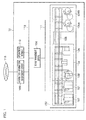
- FIG. 1 is a system configuration diagram of an automatic analysis system according to the first embodiment.
- the automatic analysis system 10 includes a testing device group 100, a device management server 108, a laboratory-information management server 109, and an operations terminal 110.
- Each device in the testing device group 100 and the device management server 108 are communicably connected through a device information network 111 such as a LAN (Local Area Network), and the device management server 108, the laboratory-information management server 109, and the operations terminal 110 are communicably connected through a test-information network 112 such as a LAN.
- the laboratory-information management server 109 is connected through a hospital network 113 to another system in a hospital such as an electronic medical record system.
- the testing device group 100 includes an input device 101, a centrifuge 102, a decapper 103, and an aliquoter 104 as preprocessing devices, a linear conveyor 105 (as a conveyor), colorimetric analyzers 106 (A, B) as analyzers, and a storing device 107 as a postprocessing device, which are arranged as illustrated in FIG. 1 .
- each of the above devices includes multiple transfer paths for each device to take in and out specimens, so that specimens can be exchanged between devices by connecting transfer paths of adjacent devices.
- the storing device 107 which collects the specimens of which the processing is completed, is arranged at the left end so that the position at which the processed specimens are collected is close to the position at which the specimens are inputted.
- Specimens to be tested which are contained in test tubes or the like, are inputted through the input device 101, which has two inlets, one for urgent specimens and the other for normal specimens.
- the urgent specimens are transferred to the centrifuge 102 in preference to the normal specimens.
- the normal specimens are transferred to the centrifuge 102 in order of input.
- centrifugation is unnecessary, the specimens taken into the centrifuge 102 are taken out toward the decapper 103, as they are.
- centrifugation is necessary, the specimens are centrifuged in batches of several tens of specimens. Thereafter, urgent ones of the centrifuged specimens are preferentially transferred to the decapper 103.
- the specimens taken into the decapper 103 from the centrifuge 102 are decapped in order of take-in, and are thereafter taken out toward the aliquoter 104.
- the aliquoter 104 receives as primary specimens the specimens taken into the aliquoter 104, and produces secondary specimens in a necessary number by pipetting predetermined amounts of the primary specimens according to the type of the test. After that, the primary specimens are transported in the reverse direction from the aliquoter 104, and collected and stored by the storing device 107.
- the produced secondary specimens are transported by the linear conveyor 105 to the colorimetric analyzers 106 (A, B).
- the colorimetric analyzers 106 (A, B) make necessary examinations of the secondary specimens taken into the colorimetric analyzers 106 (A, B), and dispose the secondary specimens after the examinations are completed.
- the preprocessing devices include the single input device 101, the single centrifuge 102, the single decapper 103, and the single aliquoter 104.
- the preprocessing devices may include more than one input device, more than one centrifuge, more than one decapper, and more than one aliquoter.
- the conveyor includes only the linear conveyor 105 in the above configuration, the conveyor may further include one or more devices for converting the transfer direction (such as an L-shaped conveyor) or one or more buffer devices temporarily storing specimens.
- Each of the colorimetric analyzers 106 (A, B) can perform analysis for multiple biochemical items.
- each of the colorimetric analyzers 106 can analyze multiple secondary specimens which are produced by aliquoting from an identical primary specimen.
- the analyzers in the described configuration are the colorimetric analyzers 106 (A, B)
- the analyzers may be one or more devices which can perform analysis for other items such as electrolytes, immunities, and DNAs, and may be one or more devices which can perform analysis for multiple items at a time.
- the multiple analyzers as above may include more than one type, and ones of the multiple analyzers may be connected.
- the postprocessing device includes only the storing device 107, the postprocessing device may further include more storing devices 107 and one or more other devices such as recappers.
- Each of the device management server 108 and the laboratory-information management server 109 may be provided in plurality according to the processing load and the like.
- the operations terminal 110 may be provided in plurality according to the layout and the manner of use of the laboratory and other factors. Moreover, the functions of the operations terminal 110 may be performed by an operations terminal of the device management server 108 or the laboratory-information management server 109.
- the layout of FIG. 1 may be changed in the present embodiment.
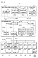
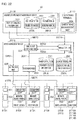
- FIG. 2 is an explanatory diagram of functions and operations of the automatic analysis system 10 according to the first embodiment. First, the functions of the automatic analysis system 10 are explained with reference to FIG. 2 .
- Each of the devices as constituents of the automatic analysis system 100 (i.e., the input device 101, the centrifuge 102, decapper 103, the aliquoter 104, the linear conveyor 105, the colorimetric analyzers 106 (A, B), and the storing device 107) has a collection portion 201 and a mechanism control portion 202.
- the device management server 108 has a tracking unit 203, a take in/out scheduling unit 204, a simulation unit 205, an instruction unit 206, a transfer route DB (database) 291, and a device model DB 292.
- the laboratory-information management server 109 has a test-information providing unit 207, a test request DB 293, and a parameters DB 294.
- the operations terminal 110 has an operations management unit 208.
- the collection portion 201 in each device in the testing device group 100 transmits a sensor value M271 indicating a state of specimen detection in each of parts in the device, to the tracking unit 203 in the device management server 108.
- the tracking unit 203 in the device management server 108 determines the current position of each specimen and calculates (as wait region information D281) the state of existence of one or more specimens in each of wait regions in which each specimen can stay, by use of the sensor value M271 for each device and a transfer route determined by test items for each specimen which is instructed to be taken in and out by an take in/out instruction M272.
- the take in/out scheduling unit 204 in the device management server 108 generates an initial take in/out schedule plan D282 in which high priority is assigned to urgent specimens, on the basis of initial condition information M273 and the wait region information D281.
- the simulation unit 205 in the device management server 108 calculates (as congestion progress information D283) estimated amounts of the wait times in each wait region up to the lapse of a predetermined length of period from the current time in the case where specimens are taken in and out in accordance with the generated take in/out schedule plan D282, by a simulation based on processing item information M274, transfer route information 291A, and device model information 292A.
- the take in/out scheduling unit 204 finally generates a take in/out schedule D284 by repeating correction of the take in/out schedule plan D282 and a simulation, where the correction of the take in/out schedule plan D282 is made by changing the timings or the order of take-in and take-out of specimens in such a manner that the estimated amounts of the wait times calculated as above do not exceed a predetermined value given by the initial condition information M273.
- the instruction unit 206 transmits the take in/out instruction M272 in accordance with the produced take in/out schedule D284 to the mechanism control portions 202 in the input device 101 and the centrifuge 102.
- the automatic analysis system 10 can suppress the wait times in each wait region in the system to or below the predetermined value, so that the TATs of the urgent specimens can be brought within a predetermined time range.
- FIG. 3 illustrates as a representative example an example of a structure of an internal mechanism of the aliquoter 104.
- the transfer mechanism which each device in the testing device group 100 has is explained in detail by taking the aliquoter 104 as an example.
- the aliquoter 104 illustrated in FIG. 3 includes conveyor lines 301 (A to E), redirection mechanisms 302 (A to H), stoppers 303 (A to H), specimen detection sensors 304 (A to I), and a processing mechanism 305.
- the conveyor lines 301 each are a mechanism which transports specimens in a predetermined direction.
- the conveyor lines 301A and 301B transport specimens rightward in FIG. 3
- the conveyor line 301C transports specimens leftward in FIG. 3 .
- the conveyor line 301B can be used for letting specimens not requiring aliquoting go through
- the conveyor line 301C can be used for taking out the primary specimens after the aliquoting.
- the redirection mechanisms 302 are mechanisms for turning the transfer directions of specimens leftward or rightward by 90 degrees, or letting the specimens go straight
- the stoppers 303 are mechanisms for temporarily stopping specimens.
- the specimen detection sensors 304 are mechanisms for detecting presence or absence of a specimen, or recognizing identification information for specimens.
- the specimen detection sensors 304 are infrared sensors, or readers of bar codes or RFID (Radio Frequency IDentification) attached to specimens per se or racks or holders conveying the specimens.
- the processing mechanism 305 is a mechanism for dispensing (aliquoting) a specimen which is stopped in the region 310 (indicated by a dashed circle on the conveyor line 301A), and is realized by, for example, feeders (feeding tubes and cups), an XYZ table, pipetters, pumps, and other components.
- the aliquoter 104 produces secondary specimens in a necessary number from a primary specimen taken in from an adjacent device, by use of the processing mechanism 305, and takes out both of the primary specimen and the secondary specimens toward an adjacent device.
- the number of specimens to be stopped and the number of specimens to be successively taken out can be controlled by changing the distances between the stoppers 303.
- the operational timings of the stoppers 303 are synchronized with a device which takes in the specimens and a device which takes out the specimens, so that it is possible to prevent collision between specimens when the specimens are handed over between the devices.
- two conveyor lines for transferring specimens rightward, a single conveyor line for transferring specimens leftward, a single processing mechanism 305, and a single conveyor line allowing the aliquoting are arranged.
- the number of device(s) provided for each purpose may be increased or decreased according to the required capacity.
- the transfer in and between the devices may be realized by use of robot arms, instead of the conveyor lines 301, the redirection mechanisms 302, and the stoppers 303.
- each of the input device 101, the centrifuge 102, the decapper 103, the colorimetric analyzers 106 (A, B), and the storing device 107 performing the other operations has an internal mechanism similar to that of the aliquoter 104, processes specimens taken into the device, and takes out the processed specimens toward the device in the next stage.
- the linear conveyor 105 does not include a processing mechanism 305, and carries out specimens which have been carried into the linear conveyor 105, to the device in the next stage.
- the aliquoter 104 is a device which processes each specimen after taking in the specimen, which is contained in a container. However, it is possible to arrange in the aliquoter 104 an external sampling device, i.e., a device for directly sampling the specimen from the linear conveyor 105 or the like, and arrange the stoppers 303 and the specimen detection sensors 304 in a part of a conveyor line in the linear conveyor 105 for setting a sampling region.
- an external sampling device i.e., a device for directly sampling the specimen from the linear conveyor 105 or the like, and arrange the stoppers 303 and the specimen detection sensors 304 in a part of a conveyor line in the linear conveyor 105 for setting a sampling region.
- the input device 101 is configured to be able to take in specimens at any timings in an any order by using an XYZ table and a robot arm, and to be able to recognize the identification information for the specimens attached to the specimens or trays.
- the centrifuge 102 is also configured to be able to take out specimens at any timings in an any order by using an XYZ table and a robot arm.
- FIG. 4 is a diagram illustrating an example of a hardware construction of each device in the testing device group 100.
- Each device in the testing device group 100 includes a CPU (Central Processing Unit) 401 which executes programs and performs calculation, a ROM (Read Only Memory) 402 which stores basic programs such as an OS (Operating System), a RAM (Random Access Memory) 403 which is used as a temporary storage area for data to be processed, an external storage 404 such as a HDD (Hard Disk Drive) or an external memory card, a communication I/F (Interface) 405 connected to the device information network 111, various sensors 406 (including specimen detection sensors 304) for use in processing and transfer of specimens, various actuators 408 (including stoppers 303) for use in processing and transfer of specimens, and a controller 407 which controls the actuators 408.
- the above constituents can exchange data with each other through a CPU bus 409.
- FIG. 5 is a diagram showing an example of a hardware construction of the device management server 108.
- the device management server 108 includes a CPU 501 which executes programs and performs calculation, a ROM 502 which stores basic programs such as an OS, a RAM 503 which is used as a temporary storage area for data to be processed, an external storage 504 such as a HDD or an external memory card, a communication I/F 505 connected to the device information network 111 and the test-information network 112, a keyboard 506 and a mouse 507 as input devices, and a display 508 as an output device.
- the above constituents can exchange data with each other through a CPU bus 509.
- FIG. 6 is a diagram illustrating an example of a hardware construction of the laboratory-information management server 109.
- the laboratory-information management server 109 includes a CPU 601 which executes programs and performs calculation, a ROM 602 which stores basic programs such as an OS, a RAM 603 which is used as a temporary storage area for data to be processed, an external storage 604 such as a HDD or an external memory card, a communication I/F 605 connected to the test-information network 112 and the hospital network 113, a keyboard 606 and a mouse 607 as input devices, and a display 608 as an output device.
- the above constituents can exchange data with each other through a CPU bus 609.
- FIG. 7 is a diagram showing an example of a hardware construction of the operations terminal 110.
- the operations terminal 110 includes a CPU 701 which executes programs and performs calculation, a ROM 702 which stores basic programs such as an OS, a RAM 703 which is used as a temporary storage area for data to be processed, an external storage 704 such as a HDD or an external memory card, a communication I/F 705 connected to the test-information network 112, a keyboard 706 and a mouse 707 as input devices, and a display 708 as an output device.
- the above constituents can exchange data with each other through a CPU bus 709.
- the collection region 201 and the mechanism control portion 202 in each device in the testing device group 100 are realized when the CPU 401 in the device executes the programs stored in the ROM 402, the RAM 403, or the external storage 404 and controls each of the hardware elements (the communication I/F405, the sensor 406, the controller 407, and the actuator 408).
- the tracking unit 203, the take in/out scheduling unit 204, the simulation unit 205, and the instruction unit 206 in the device management server 108 are realized when the CPU 501 executes the programs stored in the ROM 502, RAM 503, or the external storage 504, and controls each of the hardware elements (the communication I/F505, the keyboard 506, the mouse 507, and the display 508).
- the test-information providing unit 207 in the laboratory-information management server 109 is realized when the CPU 601 executes programs stored in the ROM 602, the RAM 603, or the external storage 604 and controls each of the hardware elements (the communication I/F605, the keyboard 606, the mouse 607, and the display 608).
- the operations management unit 208 in the operations terminal 110 is realized when the CPU 701 executes programs stored in the ROM 702, the RAM 703, or the external storage 704 and controls each of the hardware elements (the communication I/F705, the keyboard 706, the mouse 707, and the display 708).
- each device in the automatic analysis system 10 transmits to the tracking unit 203 of the device management server 108 the sensor value M271 related to the location of a specimen and received from the sensor 406.
- the mechanism control portion 202 in each device in the testing device group 100 takes in and out specimens and processes the specimens on the basis of the take in/out instruction M272 received from the instruction unit 206 in the device management server 108.
- the tracking unit 203 in the device management server 108 calculates the wait region information D281 indicating the state of stay of specimens in each wait region in each device, by using the transfer route information 291A and the sensor value M271 received from the collection portion 201 in each device in the testing device group 100.
- the wait region is a region in which a specimen is stopped or decelerated for processing or transferring the specimen, or waiting for the processing or transferring. In the mechanisms in the present embodiment, the regions immediately before the stoppers 303 can become a wait region.
- the take in/out scheduling unit 204 in the device management server 108 generates the take in/out schedule plan D282 in which priority is assigned to urgent specimens, by using the wait region information D281 and the initial condition information M273 received from the test-information providing unit 207 in the laboratory-information management server 109.
- the take in/out scheduling unit 204 corrects the take in/out schedule plan D282 by use of the congestion progress information D283 calculated by the simulation unit 205 (as explained later), and generates a final take in/out schedule D284.
- the simulation unit 205 in the device management server 108 simulates the operation of the devices, the positions of specimens, and the state of the processing, by using the device model information 292A, the wait region information D281, the take in/out schedule plan D282, and the processing item information M274 which is received from the test-information providing unit 207 in the laboratory-information management server 109, and calculates the congestion progress information D283 (variations, with time, in the wait times in each wait region).
- the instruction unit 206 in the device management server 108 transmits the take in/out instruction M272 to the input device 101, the mechanism control portion 202 in the centrifuge 102, and the like, and instructs the input device 101, the mechanism control portion 202, and the like on the order and timings of take-in and take-out of specimens, on the basis of the take in/out schedule D284.
- the transfer route DB 291 in the device management server 108 stores and manages the transfer route information 291A
- the device model DB 292 in the device management server 108 stores and manages the device model information 292A.
- the test-information providing unit 207 in the laboratory-information management server 109 generates initial condition information M273 and processing item information M274 on the basis of request information 293A stored in the test request DB 293 and scheduling parameters 294A stored in the parameters DB 294, and transmits the initial condition information M273 and the processing item information M274 to the take in/out scheduling unit 204 and the simulation unit 205 in the device management server 108.
- the test request DB 293 in the laboratory-information management server 109 stores and manages the request information 293A, which is recorded by medical doctors and laboratory technicians using the electronic medical record system and the like.
- the parameters DB 294 in the laboratory-information management server 109 stores and manages the scheduling parameters 294A, which are recorded by the medical doctors and the laboratory technicians.
- the operations management unit 208 in the operations terminal 110 performs operations including input and output for recording the transfer route information 291A, the device model information 292A, the request information 293A, and the scheduling parameters 294A in the respective types of DBs and display of the state of the processing of specimens.
- the transfer route information 291A in the automatic analysis system 10 is explained in detail with reference to FIG. 8, (a) to FIG. 8 (c) .
- the transfer route information 291A includes an item group definition table T100, a route definition table T200, and an item-route correspondence table T300.
- the item group definition table T100 defines an item group, and includes as attributes the item group ID (Identification) (T101) and the processing item ID (T102).
- the item group ID (T101) is an identifier defining an item group including multiple items of processing to be performed on a specimen
- the processing item ID (T102) is an identifier of the items of processing to be performed on the specimen.
- an item group of processing items "Biochemical Processing 1" and "Biochemical Processing 3" is defined as the item group "Biochemistry General 1”
- two records ⁇ Biochemistry General 1, Biochemical Processing 1 ⁇ and ⁇ Biochemistry General 1, Biochemical Processing 3 ⁇ are registered.
- Each device in the testing device group 100 processes each specimen on the basis of an item group or processing items. For example, in the case where centrifugal separation processing for five minutes is needed to be performed on a specimen of "Biochemistry General 1", the centrifuge 102 performs centrifugal separation processing for five minutes on the basis of the item group ID for the specimen.
- the route definition table T200 ( FIG. 8 (b) ) defines a route for transferring a specimen, and includes as the attributes the route ID (T201), the transfer order T202, the device ID (T203), the branch point ID (T204), and the branch direction T205.
- the route ID (T201) is an identifier defining of a route for transferring a specimen.
- the transfer order T202 is consecutive numbers contained in records corresponding to an identical route ID, and indicates that the specimen is to be transferred in increasing order of the consecutive numbers.
- the device ID (T203) is an identifier of a device to which the specimen is to be transferred
- the branch point ID (T204) is an identifier to indicate a branch point inside the device
- the branch direction T205 indicates to which direction the specimen is to be transferred.
- a route from the input device 101 in FIG. 1 to the aliquoter 104 is defined as "Route 1”
- records such as ⁇ Route 1, 1, Input, Branch Point 4, Upward ⁇ , ⁇ Route 1, 2, Input, Branch Point 5, Rightward ⁇ , ⁇ Route 1, 3, Centrifuge, Branch Point 2, Straight ⁇ , ⁇ Route 1, 4, Centrifuge, Branch Point 5, Straight ⁇ , ⁇ Route 1, 5, Uncap, Branch Point 2, Straight ⁇ , ⁇ Route 1, 6, Uncap, Branch Point 5, Straight ⁇ , and ⁇ Route 1, 7, Aliquot, Branch Point 2, Downward ⁇ are registered.
- the item-route correspondence table T300 ( FIG. 8 (c) ) indicates the correspondences between item groups and routes, and includes as attributes the item group ID (T301), the post-aliquot ID (T302), the aliquot quantity T303, and the route ID (T304).
- T301 the item group ID
- T302 the post-aliquot ID
- T303 the aliquot quantity
- T304 the route ID
- the correspondences between the item groups and the routes are statistic.
- the correspondences between the item groups and the routes may be dynamically changed according to the date, time, device condition, and other factors.
- the device model information 292A in the automatic analysis system 10 is explained in detail with reference to FIG. 9 (a) to FIG. 9 (d) and FIG. 10 by taking the aliquoter 104 as an example.
- the other devices can also be defined in a similar manner to the aliquoter 104.
- the device model information 292A is information for use in execution of a simulation by the simulation unit 205, and includes model objects T400, a state definition table T500, a state transition table T600, and a connection definition table T900.
- the aliquoter 104 having the internal structure illustrated in FIG. 3 is taken as an example.
- Each model object T400 ( FIG. 9 (a) ) logically represents the state of a device, and includes as attributes the current state T and one or more queues (T402, ).
- the above queues are respectively in one-to-one correspondence with the wait regions in the device, and each queue is a collection (container) which holds specimen IDs in the order in which specimens are taken into the corresponding wait region, where the specimen IDs are identifiers of the specimens.
- a queue ID is assigned to each queue, where the queue ID is unique in the entire automatic analysis system 10.
- a capacity (queue size) corresponding to the hardware specification of the device is preset, and each queue holds the number of specimens which can be taken in. Therefore, the state of available space in each queue as a constituent of the model object T400 can be determined by appropriately storing in the queue the specimen IDs of specimens existing in the corresponding wait region.
- FIG. 10 indicates the internal mechanism of the aliquoter 104 illustrated in FIG. 3 in a queue model representation by associating a queue with each hardware element in the internal mechanism of the aliquoter 104.
- FIG. 10 indicates, for example, that specimens can be transferred from the backward wait queue T402 (having the queue size of five) corresponding to the conveyor line 301C of FIG. 3 to the forward wait queue 1 (T403) (having the queue size of five) corresponding to the conveyor line 301B and the forward wait queue 2 (T404) (having the queue size of five) corresponding to the conveyor line 301A.
- the model object T400 indicating the state of the aliquoter 104 (illustrated in FIG.
- the queues contained in the device include the backward wait queue T402 (having the queue size of five), the forward wait queue 1 (T403) (having the queue size of five), the forward wait queue 2 (T404) (having the queue size of five), an adjustment queue T405 (having the queue size of three), a primary operation queue T406 (having the queue size of three), a secondary operation queue 1 (T407) (having the queue size of three), and a secondary operation queue 2 (T408) (having the queue size of three).
- FIG. 10 indicates only the connections between the queues in the aliquoter 104, connections with queues in adjacent devices are defined in the connection definition table T900 ( FIG. 9 (d) ), which is explained later.
- an identifier of the current state (state ID) is stored, where the identifier indicates which of the states defined in the state definition table T500 the current state of the device is.
- the state definition table T500 ( FIG. 9 (b) ) defines the state of the device in correspondence with processing of specimens.
- the state definition table T500 for the aliquoter 104 includes as attributes the state ID (T501), the primary operation queue T502, the secondary operation queue 1 (T503), and the secondary operation queue 2 (T504).
- a record such as ⁇ S0, No Specimen, No Specimen, No Specimen ⁇ is registered for an initial state (e.
- the queues affecting the aliquoting process i.e., only the primary operation queue T406, the secondary operation queue 1 (T407), and the secondary operation queue 2 (T408)
- the queues not affecting the aliquoting process i.e., the backward wait queue T402, the forward wait queue 1 (T403), the forward wait queue 2 (T404), and the adjustment queue T405 are not considered.
- the state transition table T600 ( FIG. 9 (c) ) defines transitions of the state of the device caused by performing processing in accordance with the processing item information M274 for a specimen, and the time needed for the processing.
- the state transition table T600 for the aliquoter 104 includes as attributes the transition source state T601, the transition destination state T602, the transition condition T603, and the processing time T604.
- a record such as ⁇ S1, S2, "Condition for Transition from S1 to S2", 400 (milliseconds) ⁇ is registered.
- the processing time T504 is assumed to be constant in the present embodiment. However, in the case where the processing time varies with the circumstances, it is possible to add an attribute indicating a variable condition and set the processing time according to the condition, or represent the processing time as a probability distribution such as a normal distribution.
- the connection definition table T900 ( FIG. 9 (d) ) indicates, for all the queues set in the model objects T400 for the respective devices, connections between the queues in each device and connections between queues in different devices, and includes as attributes the transfer source queue ID (T901), the device ID (T902), the branch point ID (T903), the branch direction T904, and the transition destination queue ID (T905).
- T901 the transfer source queue ID
- T902 the device ID
- T903 the branch point ID
- T904 the branch direction
- T905 transition destination queue ID
- the queue IDs stored in the transfer source queue ID (T901) and the transfer destination queue ID (T905) are the identifiers of the queues included in the model objects T400 of the devices.
- the device ID (T902) and the branch point ID (T903) correspond to the device ID (T203) and the branch point ID (T204) in the route definition table T200 (see FIG. 8 ), so that the queues are associated with the transfer routes.
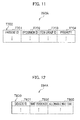
- the request information 293A in the automatic analysis system 10 is explained in detail with reference to FIG. 11 .
- the request information 293A includes a test request information table T700.
- the test request information table T700 indicates processing items needed for testing and priorities, and includes as attributes the patient ID (T701), the specimen ID (T702), the item group ID (T703), and the priority T704.
- the scheduling parameters 294A in the automatic analysis system 10 are explained in detail with reference to FIG. 12 .
- the scheduling parameters 294A include a scheduling parameter table T800.
- the scheduling parameter table T800 indicates the wait time which is allowable in each wait region in each device, and includes as attributes the device ID (T801), the wait region ID (T802), and the allowable wait time T803.
- the automatic analysis system 10 generates such a take in/out schedule plan that the wait time of each of the specimens including the urgent specimens does not exceed the allowable wait time T803, and controls take-in and take-out. Therefore, when the allowable wait time T803 is appropriately set, the TATs of the urgent specimens can always be brought within a target time range.
- the sensor value M271 ( FIG. 13 (a) ) indicates one of the detection results of the specimen detection sensors 304 arranged in respective parts in the devices in the testing device group 100, and includes the detection time M2711, the device ID (M2712), the sensor ID (M2713), and the value M2714.
- the value M2714 is a binary value indicating whether or not a specimen is on the sensor, is "1" when a specimen is on the sensor, and is "0" when no specimen is on the sensor.
- the take in/out instruction M272 ( FIG. 13 (b) ) indicates the order and timings of take-in and take-out of specimens from each device, and includes multiple sets of the time of take-in or take-out M2721, the specimen ID (M2722), and the indication value M2723 indicating take-in or take-out.
- the initial condition information M273 ( FIG. 13 (c) ) indicates an initial condition for scheduling, and includes multiple sets of the specimen ID (M2731) and the priority M2732 and multiple sets of the device ID (M2733), the wait region ID (M2734), and the allowable wait time M2735.
- the processing item information M274 ( FIG. 13 (d) ) indicates processing items for each specimen, and includes multiple sets of the specimen ID (M2741) and the item group ID (M2742).
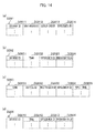
- the wait region information D281 ( FIG. 14 (a) ) is information indicating the state of stay of specimens and the queue order of the specimens in each wait region in the devices in the testing device group 100, and includes the device ID (D2811), the wait register (D2812), the queue order (D2813), and the specimen ID (D2814).
- the queue order is represented by assigning the consecutive numbers 1, 2, 3, ... to the specimens from the leading specimen.
- the take in/out schedule plan D282 ( FIG.
- the take in/out schedule plan D282 includes the device ID (D2821), the time D2822, the specimen ID (D2823), and the indication value D2824.
- the indication value D2824 indicates take-in or take-out in a similar manner to the indication value M2723 in the take in/out instruction M272.
- the congestion progress information D283 ( FIG. 14 (c) ) is information indicating time variations of the wait time of the specimen in each wait region in a device estimated by simulation, where the wait time may include the time for processing performed on the specimen.
- the congestion progress information D283 includes the time D2831, the device ID (D2832), the wait region ID (D2833), the specimen ID (D2834), and the wait time D2835.
- the take in/out schedule D284 ( FIG. 14 (d) ) indicates a plan of take-in and take-out which is finally determined by the take in/out scheduling unit 204.
- the take in/out schedule D284 includes the device ID (D2841), the time D2842, the specimen ID (D2843), and the indication value D2844.
- the indication value D2844 indicates take-in or take-out in a similar manner to the indication value M2723 in the take in/out instruction M272.
- Each device in the present embodiment performs the processing corresponding to the processing item IDs (T102) (see FIG. 8 ), on each specimen taken in, and takes out the processed specimen.
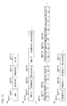
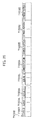
- the device management server 108 performs the following processing, for example, every second. Although the processing is performed every second in this example, the intervals between the performances of the processing may be shorter or longer than one second according to the processing capacity of the device management server 108 or the like.
- step S101 the tracking unit 203 calculates the state of stay of specimens in each wait region (i.e., in each queue in each model object T400) on the basis of the take in/out instruction M272, the sensor value M271 received from the collection portion 201 of each device in the testing device group 100, and the transfer route information 291A, and then calculates the wait region information D281.
- step S102 the take in/out scheduling unit 204 calculates the state of each device according to the state definition table T500 (see FIG. 9 ), and makes an initial setting of each model object T400.
- step S103 the take in/out scheduling unit 204 issues a request to the test-information providing unit 207, and acquires the initial condition information M273.
- the test-information providing unit 207 generates the initial condition information M273 from the request information 293A and the scheduling parameters 294A.
- step S104 the take in/out scheduling unit 204 generates the take in/out schedule plan D282 in such a manner that specimens are taken in and taken out with the maximum processing performance and the specimens for which the priority T704 is highly set in the test request information table T700 (see FIG. 11 ), the specimens which are loaded in the input tray or inlet for urgent specimens, and the urgent specimens which are suddenly inputted take precedence.
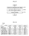
- the device ID "Input 1" is assigned to the input device 101, that the input device 101 has three types of trays (a tray 3001A for urgent specimens, a tray 3001B for normal specimens, and a tray 3001C for specimens not undergoing centrifugation), and that specimens can be inputted from an arbitrary tray at the rate of one specimen every four seconds at the highest.
- the initial take in/out schedule plan D282 generated at this time as above includes information as the take-in schedule plan 3002 ( FIG. 30 (b) ). That is, the order of take-in is planned in such a manner that urgent specimens are preferentially taken in in order of arrival, and thereafter normal specimens are taken in in order of arrival. The times of take-in are planned in such a manner that specimens are taken in at the maximum processing speed of the input device 100, specifically at the rate of one specimen every four seconds.
- the simulation unit 205 issues a request to the test-information providing unit 207, and acquires the processing item information M274 (in step S105). At this time, in response to the above request, the test-information providing unit 207 generates the processing item information M274 from the request information 293A.
- the simulation unit 205 calculates (simulates) a state transition or transitions during the ten-minute period starting from the current time, by use of the current state of each device, the processing items for each specimen, the state transition table for each device, and the like, and calculates the congestion progress information D283 in which the wait time of each specimen is estimated, for example, at intervals of 100 milliseconds.
- the period for which the state transition is calculated may be shorter or longer than ten minutes according to the processing performance of the device management server 108.
- the wait time of each specimen is estimated at intervals of 100 milliseconds in the present embodiment, the intervals may be set shorter or longer than 100 milliseconds.
- step S107 the simulation unit 205 determines whether or not the wait times D2835 of all the specimens in the congestion progress information D283 are equal to or lower than the allowable wait times M2735, respectively, which are predetermined values in the initial condition information M273.
- the operation goes to step S109.
- the operation goes to step S108.
- step S108 the take in/out scheduling unit 204 goes back to immediately before the take-in or take-out of the specimen of which wait time exceeds the allowable wait time earliest, generates a new take in/out schedule plan D282 by delaying and correcting the times of take-in and take-out of specimens (in step S108), and performs the processing in step S106 and the following steps again. Details of the processing in step S108 are explained later.
- the take in/out scheduling unit 204 passes to the instruction unit 206 the contents of the current take in/out schedule plan D282 as a final take in/out scheduling D284, and the instruction unit 206 transmits the take in/out instruction M272 instructing take-in and take-out of specimens to the mechanism control portion 202 of a corresponding one or ones of the devices in the testing device group 100.
- the processing of FIG. 15 is completed (in step S109).
- the mechanism control portion 202 which is instructed to take in and out the specimens performs control of the mechanism so as to take in and out the specimens in accordance with the instruction.
- step S101 in FIG. 15 processing for calculating which wait region each specimen is located in is explained in detail with reference to FIG. 16 .
- the above processing is assumed to be asynchronously performed for each wait region.
- the tracking unit 203 performs the processing in step S202 and the steps thereafter on the specimens until the wait regions of all the specimens are calculated.
- the processing of FIG. 16 is completed (in step S201).
- the tracking unit 203 acquires (in step S202) a transfer route of the specimen from the transfer route information 291A ( FIG. 8 ).
- step S203 the tracking unit 203 acquires from the received sensor values M271 the newest sensor value matching the specimen. Subsequently (in step S204), the tracking unit 203 determines the wait region of the specimen and the queue order thereof by use of the newest sensor value acquired as above, adds the record to the wait region information D281, and registers the record.
- the above wait region is determined to be: (1) a wait region corresponding to the location of one of the specimen detection sensors 304 which gives the newest sensor value, when the specimen is stopped by the stoppers 303 or the like and is in the state in which the specimen can be detected; and (2) a wait region to which the specimen goes next from the location of one of the specimen detection sensors 304 which gives the newest sensor value, which location is in the transfer route acquired from the transfer route information 291A, when the specimen is in the state in which the specimen is not yet detected.
- step S106 of FIG. 15 processing for calculation of the congestion progress information is explained in detail with reference to FIG. 17 .
- the above processing is performed for each model object in parallel.
- the simulation unit 205 sets the simulation time to the current time, and sets the current states of the devices in the model objects T400 (see FIG. 9 ).
- the states of the devices calculated in step S 102 in FIG. 15 are set as the current states of the model objects T400, and the state of wait of each specimen acquired from the wait region information D281 (see FIG. 14 ) is set in the queues in the model object T400.
- step S302 the simulation unit 205 selects one of the state transitions defined in the state transition table T600 which satisfies the transition condition at the earliest time, by reference to the processing item information M274 for each specimen acquired in step S 105 in FIG. 15 .
- the completion time which is ten minutes after the current time
- the operation of the simulation unit 205 proceeds to step S304.
- the simulation time exceeds the completion time, the processing of FIG. 17 is completed (step S303 ⁇ End).
- the simulation unit 205 determines (in step S304) whether or not the time needed for state transition satisfying the transition condition elapses, by reference to the state transition table T600. When it is determined that the time needed for state transition elapses (i.e., when yes is determined), the operation goes to step S305. When the time needed for state transition does not elapse (i.e., when no is determined), the operation goes to step S309.
- step S305 determines whether or not a specimen to be taken out to the next wait region as a result of the state transition exists.
- the operation goes to step S306.
- no specimen to be taken out exists i.e., when no is determined
- the operation goes to step S308.
- step S306 determines (in step S306) whether or not an available space exists in the queue to which the specimen is to be taken out, by reference to the model object T400 for a device containing the queue which is the destination of the specimen to be taken out.
- step S307 When it is determined that an available space exists in the queue which is the destination of the specimen to be taken out (i.e., when yes is determined), the operation goes to step S307.
- no available space exists in the queue which is the destination of the specimen to be taken out i.e., when no is determined
- the operation goes to step S309.
- the simulation unit 205 takes out the specimen to the queue as the destination of the specimen to be taken out (in step S307). Specifically, the simulation unit 205 makes a reservation for taking in a specimen which is to be taken out, into each queue as a destination of the specimen to be taken out, namely into the queue on which simulation is performed in parallel to the queue from which the specimen is taken out. In addition, the simulation unit 205 waits the time needed for the take-out, which is acquired on the basis of the corresponding processing time T604 in the state transition table T600.
- the simulation unit 205 deletes the data corresponding to the specimen from the queue from which the specimen is taken out. Further, the simulation unit 205 adds the time needed for the take-out to the wait time D2835, in the record of the congestion progress information D283, of each specimen remaining in the queue from which the specimen is to be taken out, and updates the time D2831 in the record of the congestion progress information D283.
- the reservation for the take-in of the specimen is used as input data when the simulations for the other devices are performed, and is also used, when the available space in the queue as the destination is determined in step S306, for determining whether or not the space in the queue as the destination is exhausted by other specimens which are taken into the queue as the destination earlier than the concerned specimen.
- step S307 After execution of step S307 is completed, or in the case where no specimen to be taken out exists (i.e., no is determined in step S305), the simulation unit 205 updates the state of the corresponding device by changing the current state T401 in the model object T400 to the state ID corresponding to the state after the transition according to the state transition table T600 (in step S308). Thereafter, the operation goes back to step S302, and the operations explained above are repeated.
- step S304 When the elapsed time does not reach the time needed for the state transition (i.e., no is determined in step S304), or when no available space exists in the queue as the destination (i.e., no is determined in step S306), the simulation unit 205 increments the time so as to advance the simulation time by 100 milliseconds (in step S309). Thereafter, the operation goes back to step S303, and the operations explained above are repeated.
- step S108 processing for correcting the take in/out schedule plan D282 is explained in detail with reference to FIG. 18 .
- the take in/out scheduling unit 204 extracts a specimen of which the wait time D2835 registered in the congestion progress information D283 as a result of the simulation exceeds, at the earliest (first) time, the predetermined value (the allowable wait time M2735) for the corresponding wait region.
- the time at which the predetermined value for the specimen being already taken out is exceeded is calculated by subtracting the difference between the wait time D2835 and the allowable wait time D2735 from the time D2831, and the time at which the predetermined value for the specimen being not yet taken out is exceeded is calculated by adding the allowable wait time D2735 to the time D2831 in the record for the last take-out registered in the congestion progress information D283.
- the take in/out scheduling unit 204 determines whether or not centrifugation is unnecessary for the objective specimen (in step S402). When it is determined that the objective specimen does not need centrifugation (i.e., when yes is determined), the operation goes to step S403. When the objective specimen needs centrifugation (i.e., when no is determined), the operation goes to step S404. When the objective specimen does not need centrifugation (i.e., when yes is determined in step S402), the take in/out scheduling unit 204 adjusts the time of take-out from the centrifuge 102 (in step S403).
- the take in/out schedule plan D282 is corrected in such a manner that the time of take-out of each of other specimens using the same transfer path as the objective specimen in a time range around the time at which the objective specimen is transferred to the centrifuge 102 is delayed by two seconds.
- the take in/out scheduling unit 204 adjusts the time of take-in from the input device 101 (in step S404).
- the take in/out schedule plan D282 is corrected in such a manner that the times at which a specimen two specimens preceding the objective specimen and the following specimens are taken in from the input device 101 are each delayed by two seconds.
- the processing (in step S403) for adjusting the time of take-out from the centrifuge 102 suppresses take-out of normal specimens from the centrifuge and preferentially processes urgent specimens.
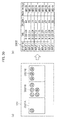
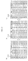
- the time of take-in of each of the specimens S7, S8, and S9 is delayed by two seconds (in accordance with the take-in schedule plan 3102 according to the first correction ( FIG. 31 (b) ).
- a second correction is made.
- the time of take-in of each of the specimens S7, S8, and S9 is delayed by four seconds from the original time of take-in (in accordance with the take-in schedule plan 3103 according to the second correction ( FIG. 31 (c) ).
- the correction of the take in/out schedule plan D282 is completed. Further, in the second and following corrections, the number of preceding specimens of which the times of take-in are delayed may be successively increased.
- the time of take-out or take-in is delayed by two seconds in each correction.
- the amount of the increase in the delay may be greater or smaller than two seconds according to the processing performance of the device management server 108.
- the number of preceding specimens of which the times of take-in are delayed is two.
- the number of preceding specimens of which the times of take-in are delayed may be greater or smaller than two.
- the adjustment of the time of take-in from the input device 101 may be dispensed with.
- the processing in the present embodiment is performed in a heuristic manner, it is possible to define as operators operations of changing the order and times of take-in and take-out, and also use an optimization method such as the Monte Carlo method. Even in the above case, it is possible to quickly make the correction by intensively adding corrections in a time range around a time of take-in or take-out of a specimen of which the wait occurs. Moreover, in the present embodiment, the correction is performed for a single specimen of which wait time exceeds the allowable wait time at the earliest time. However, corrections for multiple specimens the wait times of which exceed the allowable wait time may be made at once.
- the schedule plan is corrected by performing the simulation for the ten-minute period starting from the current time, at intervals of 100 milliseconds.
- the schedule plan may be corrected by detecting occurrence of congestion on the basis of the number of specimens in the wait region and the position of the wait region.
- FIG. 19 is a flow chart indicating an example of processing for registering the scheduling parameter table T800
- FIG. 20 is a flow chart indicating an example of display of a screen for registering scheduling parameters, which is used in the processing for registering the scheduling parameter table T800.
- Input into and output from the screen for registering scheduling parameters are controlled by the operations management unit 208 in the operations terminal 110.
- a person who performs operation for registration such as a laboratory technician chooses an arbitrary item group from item groups registered in advance by using an item-group combo box G101 (in step S501).
- a transfer route of a specimen corresponding to the chosen item group is graphically displayed on a flow view G102. Therefore, the person performing the operation for registration chooses a representative specimen for which parameter is to be registered, from among transferred specimens (primary specimens and aliquoted secondary specimens), by confirming the transfer route displayed on the flow view G102 and using a representative-specimen combo box G103 (in step S502).
- an estimated time of the TAT for the case where processing is performed in the shortest time is displayed in a shortest-processing-time box G104.
- the above estimated time is a result of a simulation performed in advance on the assumption that only one specimen in the corresponding item group is processed in the simulation.
- a maximum delay time which is allowable when the chosen representative specimen is an urgent specimen is set by using an allowable-delay-time combo box G105.
- the operations management unit 208 registers an allowable wait time T803 in each wait region in each device in a record for the wait region in the device in the scheduling parameter table T800 (in step S504), where the allowable wait time T803 in each wait region in each device is the sum of the wait time (T1) in the wait region in the device which occurs when the device operates with the maximum processing performance without wait and the quotient (T2) obtained by dividing of the maximum delay time divided by the number of wait regions through which the specimen is to be transferred.
- the person performing the operation for registration can quit the operation for registration by pressing on the Cancel button G107.
- the wait times of all specimens as urgent specimens and normal specimens in each wait region can be suppressed to or below a predetermined value, so that the TATs of the urgent specimens can always be brought within a target time range.
- FIG. 21 is a system configuration diagram of the automatic analysis system according to the second embodiment.
- the automatic analysis system 20 includes a testing device group 2100, a device management server 2115, a laboratory-information management server 2116, and an operations terminal 2117.
- Each device in the testing device group 2100 and the device management server 2115 are communicably connected through a device information network 2118 such as a LAN.
- the device management server 2115, the laboratory-information management server 2116, and the operations terminal 2117 are communicably connected through a test-information network 2119 such as a LAN.
- the laboratory-information management server 2116 is connected through a hospital network 2120 to another system in a hospital such as an electronic medical record system.
- the testing device group 2100 includes a recapper 2101, a storing device 2102, an input device 2103, a centrifuge 2104, a decapper 2105, an aliquoter 2106, linear conveyors 2107 and 2111, redirectors 2108 and 2112, buffer devices 2109 and 2113 capable of changing the order of take-out of specimens, colorimetric analyzers 2110 (A, B), and immunoassay devices 2114 (A, B), which are arranged as illustrated in FIG. 21 .
- FIG. 22 is an explanatory diagram indicating functions and operations of the automatic analysis system 20 according to the second embodiment. Firstly, the functions and operations of the automatic analysis system 20 are explained with reference to FIG. 22 .
- Each device as a constituent of the testing device group 2100 has a collection portion 201 and a mechanism control portion 202.
- the device management server 2115 includes a tracking unit 203, a take in/out scheduling unit 204, a simulation unit 205, an instruction unit 206, a transfer route DB 291 and a device model DB 292.
- the laboratory-information management server 2116 includes a test-information providing unit 207, a test request DB 293, and a parameters DB 294.
- the operations terminal 2117 includes an operations management unit 208.
- the following first and second cases are considered.
- a specimen requiring a high aliquot ratio is inputted before input of an urgent specimen, so that the processing capacity of the aliquoter 2106 is exceeded, and congestion occurs on the upstream side of the aliquoter 2106.
- the "return movement" for example, for examining a specimen in the colorimetric analyzer 2110 (A, B) and thereafter examining the specimen in the immunoassay device 2114 (A, B), frequently occur, so that the processing capacity of the redirector 2108 is exceeded, and congestion occurs on the upstream and downstream sides of the redirector 2108.
- the collection portion 201 in each device as a constituent of the testing device group 2100 transmits the sensor value M271 indicating the state of specimen detection in each of parts of the device to the tracking unit 203 in the device management server 2115.
- the tracking unit 203 in the device management server 2115 determines the current position of each specimen and calculates the state of existence of one or more specimens (the wait region information D281) in each region in which a specimen can stay in each device, by using the sensor value M271 from each device and the transfer route determined by the test item of each specimen which is instructed by the take in/out instruction M272 to take in or out.
- the take in/out scheduling unit 204 in the device management server 2115 generates an initial take in/out schedule plan D282 in which priority is assigned to urgent specimens, on the basis of the initial condition information M273 and the wait region information D281.
- the simulation unit 205 in the device management server 2115 calculates estimated amounts of the wait times in each wait region in a period until a predetermined time elapses (the congestion progress information D283) in the case where specimens are taken in and out in accordance with the generated take in/out schedule plan D282, by a simulation based on the processing item information M274, the transfer route information 291A, and device model information 292B.
- the take in/out scheduling unit 204 repeats a correction of the take in/out schedule plan D282 and a simulation as above so as to bring the estimated amounts of the wait times equal to or below a predetermined value given by the initial condition information M273, where the timings and order of take-in and take-out are changed in the correction of the take in/out schedule plan D282.
- the take in/out schedule D284 is generated in the end.
- the instruction unit 206 transmits the take in/out instruction M272 to the mechanism control portions 202 in the input device 2103, the centrifuge 2104, and the buffer devices 2109 and 2113 in accordance with the produced take in/out schedule D284.
- the above operations of the automatic analysis system 20 can suppress the wait times in each wait region in the system to a value equal to or below the predetermined value, and can therefore bring the TATs of the urgent specimens within a predetermined time range.
- the structures of the internal mechanisms of the devices other than redirectors 2108 and 2112 are similar to the internal mechanisms of the devices explained in the first embodiment.
- the input device 2103 can take in specimens at any timings in an any order by using an XYZ table and a robot arm, and can recognize the identification information for the specimens attached to the specimens or trays.
- specimens can also be taken out from the centrifuge 2104 and the buffer devices 2109 and 2113 at any timings in an any order by using the XYZ table and the robot arm.
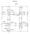
- FIG. 23 illustrates an example of a structure of an internal mechanism of the redirector 2108.
- the transfer mechanisms in the redirectors 2108 and 2112 are explained in detail below with reference to FIG. 23 .
- the redirector 2108 illustrated in FIG.23 includes conveyor lines 2301, redirection mechanisms 2302, stoppers 2303, and specimen detection sensors 2304.
- the function of each of the above mechanisms in the redirector 2108 is similar to the function of the corresponding mechanism in the first embodiment explained before.
- regions as the redirection mechanisms 2302 which need exclusive control are referred to as common portions.
- specimens in the redirector 2108 are transferred from one queue to another queue in each control cycle (e.g., every second).
- multiple queues are concurrently processed unless specimens transferred to or from the multiple queues go through the same common portion.
- FIG. 24 which represents by a queue model the structure of the internal mechanism of the redirector illustrated in FIG. 23
- the transfer from the queue 4 to the queue 12 and the transfer from the queue 6 to the queue 10 can be performed in the same control cycle.
- the transfer from the queue 4 to the queue 12 and the transfer from the queue 8 to the queue 5 cannot be performed in the same control cycle, because both of the transfers use the common portion illustrated in the upper left part of FIG. 24 .
- the specimens transferred from the queue 1 to the queue 6 and the specimens transferred from the queue 5 to the queue 9 use the same common portion illustrated in the lower left part of FIG. 24 .
- the redirector 2108 it is possible to control the queues in such a manner that the queue 1 always precedes the queue 5 in transfer of specimens, and specimens are transferred from the queue 1 to the queue 6 until no specimen is left in the queue 1. Therefore, in the redirector 2108, (1) the performance of transfer of specimens is lowered when the same common portion is concurrently used in multiple transfer routes compared with when no common portion is concurrently used in multiple transfer routes. In addition, (2) the balance in the transfer performance between different transfer directions in the redirector 2108 can be adjusted by controlling the priorities assigned to queues from which the transfers use the same common portion.
- each device in the testing device group 2100 is similar to the hardware construction of each device in the testing device group 100 explained in the first embodiment.
- the hardware construction of the device management server 2115 is similar to the hardware construction in the device management server 108 which is explained in the first embodiment.
- the hardware construction of the laboratory-information management server 2116 is similar to the hardware construction of the laboratory-information management server 109 explained in the first embodiment.
- the hardware construction of the operations terminal 2117 is similar to the hardware construction of the operations terminal 110 explained in the first embodiment.
- the correspondences between the functions and the hardware in each device in the automatic analysis system 20 are similar to the first embodiment except that the device model information 292B replaces the device model information 292A.
- the information structure of the automatic analysis system 20 are similar to the first embodiment except that the device model information 292B replaces the device model information 292A. Therefore, only the device model information 292B in the automatic analysis system 20 is explained in detail below with reference to FIGs. 9 , 23 , 24 , and 25 .
- the device model information 292B is information for use by the simulation unit 205 in execution of the simulation, and includes the model objects T400, the state definition table T500, the state transition table T600, and the connection definition table T900 (which are illustrated as examples in FIG. 9 ) and the state definition table T1000 for redirectors (illustrated as an example in FIG. 25 ).
- the model objects T400, the state definition table T500, the state transition table T600, and the connection definition table T900 are similar to those explained in the first embodiment.
- the take in/out schedule D284 ( FIG. 14 ) has the same structure as the first embodiment.
- the indication values D2844 for the redirectors 2108 and 2112 each indicate the direction in which specimens are to be preferentially taken in, instead of indicating whether to take in or take out.
- the indication values D2844 for the redirectors 2108 and 2112 are each one of the integers (0, 1, 2, 3, and 4) for respectively indicating "No Priority”, “Left First”, “Down First”, “Right First”, and “Up First”, which are listed as preferential take-in directions in the preferred-queue determination rule table T2000 ( FIG. 28 ) (which is explained later).
- the state definition table T1000 for redirectors illustrated in FIG. 25 defines the state of the redirector 2108, and includes as attributes the state ID (T1001), the queues 1 to 12 (T1002A to T1002L), and the common portions 1 to 4 (T1003A to T1003D).
- the common portions indicate the states of use of regions which need exclusive control as the redirection mechanisms 2302 (A to D) in FIG. 23 .
- the reason for adding the states of use to the state definition table for the redirector 2108, but not to the state definition table for the other devices, is to prescribe the exclusive control operation mentioned before. Since the transfer directions and transfer times of specimens are set for each state discriminately defined in the state definition table T1000 for redirectors, more precise simulation is enabled.
- each device in the present embodiment is assumed to process specimens taken in, in accordance with the processing item IDs (see T102 in FIG. 8 ), and take out the processed specimens.
- the basic flow of processing in the second embodiment is similar to flow of processing in the first embodiment except the concurrent use of the state definition table T500 and the state definition table T1000 for redirectors and the processing for correction of the take in/out schedule plan.
- step S601 the take in/out scheduling unit 204 extracts a specimen of which the wait time D2835 registered in the congestion progress information D283 as a result of a simulation exceeds the predetermined value (the allowable wait time M2735) in the corresponding wait region at the earliest time.
- the manner of calculation of the time at which the predetermined value is exceeded is similar to step S401 (in FIG. 18 ), which is explained before.
- step S602 the take in/out scheduling unit 204 determines, by reference to the congestion progress information D283, whether or not a wait occurs around the redirector 2108 or 2112 and many return movements in which specimens go through an identical wait region multiple times occur.
- the operation goes to step S603. Otherwise (i.e., when no is determined), the operation goes to step S605.
- the take in/out scheduling unit 204 adjusts the times of take-out from the buffer devices 2109 and 2113 (in step S603). Specifically, the take in/out scheduling unit 204 corrects the take in/out schedule plan D282 so as to delay by two seconds the times of take-out of normal specimens in the buffer devices 2109 and 2113, in the time range around the time at which the objective specimen is taken out from the buffer device 2109 or 2113. In the above operation, when 30% or more of specimens taken into the redirectors 2108 and 2112 make a return movement, the take in/out scheduling unit 204 determines that many return movements occur.
- the take in/out scheduling unit 204 performs priority control of the redirectors 2108 and 2112 (in step S604). Specifically, the take in/out scheduling unit 204 controls the redirectors 2108 and 2112 so as to preferentially transfer specimens from a wait region which is most congested with specimens (i.e., a wait region in which the sum of wait times of specimens is greatest) in the devices adjacent to the redirectors 2108 and 2112 in respective directions (e.g., the linear conveyors 2107 and 2111 and the buffer device 2109 adjacent to the redirector 2108).
- the priority control according to the present embodiment is performed on the adjacent devices, the priority control may be performed on the aliquoter 2106 and the buffer device 2113, instead of the linear conveyors 2107 and 2111 which do not directly contribute to the congestion of specimens.
- step S605 determines whether or not centrifugation of the objective specimen is unnecessary.
- the operation goes to step S606. Otherwise (i.e., when no is determined), the operation goes to step S607.
- the take in/out scheduling unit 204 adjusts the times of take-out from the centrifuge 2104 (in step S606).
- the take in/out scheduling unit 204 corrects the take in/out schedule plan D282 so as to delay by two seconds the times of take-out, from the centrifuge 2104, of normal specimens other than the objective specimen which use the same transfer path as the objective specimen in the time range around the time of transfer of the objective specimen in the centrifuge 2104.
- the take in/out scheduling unit 204 adjusts the times of take-in from the input device 2103 (in step S607).
- the take in/out schedule plan D282 is corrected in such a manner that the times at which a specimen which precedes the objective specimen by two specimens and the following specimens are taken in are each delayed by two seconds.
- the processing (in step S603) for adjusting the times of take-out from the buffer devices and the processing (in step S604) for priority control of the redirectors guarantee the TAT and operate the system with high efficiency by suppressing take-out of specimens from the analyzer and preferentially processing urgent specimens.
- a set of queues on the source side from which specimens can be transferred, by one operation, to each queue (e.g., each of the queues 9, 10, 11, and 12 in FIG. 24 ) corresponding to an outlet of a redirector is defined as a "block".
- the block 1 is constituted by the queues 1 and 5
- the block 2 is constituted by the queues 2 and 6
- the block 3 is constituted by the queues 3 and 7
- the block 4 is constituted by the queues 4 and 8.
- step S701 one of the directions from the adjacent devices including a specimen which will have to wait the longest time (which is referred to as the maximum-wait direction) and the longest wait time per se (which is referred to as the maximum wait time) are obtained by calculation by reference to the congestion progress information D283.
- the priority order of the queues is set on the basis of the preferred-queue determination rule table (T2000) illustrated in FIG. 28 (in step S702). Specifically, when the maximum wait time does not exceed the predetermined value for each wait region, the order indicated as "No Priority" is set.
- the queue 5 precedes the queue 1 in the block
- the queue 6 precedes the queue 2 in the block 2
- the queue 7 precedes the queue 3 in the block 3
- the queue 8 precedes the queue 4 in the block 4.
- the maximum-wait direction is determined to be the preferred take-in direction.
- the preferred take-in direction is determined to be "Right First”
- the priority order is set in such a manner that the queue 5 precedes the queue 1 in the block, the queue 6 precedes the queue 2 in the block 2, the queue 3 precedes the queue 7 in the block 3, and the queue 8 precedes the queue 4 in the block 4.
- a transfer control schedule for each queue is produced by calling a SolveBlock process with an identifier (as an argument) indicating each block, where the processing is successively performed, by reference to the congestion progress information D283, for the respective blocks in decreasing order of the wait time which a specimen included in the direction corresponding to each block from the adjacent devices will have to wait.
- the SolveBlock process is explained later.
- the queue determined to be preferred in each block corresponding to the block identifier is referred to as a high priority queue, and the other queues are referred to as low priority queues.
- step 5801 it is determined whether or not the current call for the SolveBlock process is the fourth call.
- the operation goes to step S802. Otherwise (i.e., when yes is determined), the operation goes to step S818.
- step S802 When the current call for the SolveBlock process is the fourth call (i.e., when no is determined in step S801), it is determined (in step S802) whether or not the high priority queue containing a specimen which has not yet been transferred exists. When it is determined that the high priority queue contains a specimen which has not yet been transferred (i.e., when yes is determined), the operation goes to step S803. Otherwise (i.e., when no is determined), the operation goes to step S810.
- step S803 When the high priority queue contains a specimen which has not yet been transferred (i.e., when yes is determined in step S802), it is determined (in step S803) whether or not the destination is one of the queues 9, 10, 11, and 12 and the specimen can be transferred to the destination (i.e., the queue has a space and any of the common portions is unused). When it is determined that the destination is one of the queues 9, 10, 11, and 12 and the specimen can be transferred to the destination (i.e., when yes is determined), the operation goes to step S804. Otherwise (i.e., when no is determined), the operation goes to step S805.
- step S803 When the destination is one of the queues 9, 10, 11, and 12 and the specimen can be transferred to the destination (i.e., when yes is determined in step S803), it is determined to transfer the specimen in order of the priority of the queue, and the processing is completed (in step S804).
- step S803 it is determined whether or not the specimen can be transferred to the queue as the destination of the specimen (in step S805).
- the operation goes to step S808. Otherwise (i.e., when no is determined), the operation goes to step S806.
- the specimen cannot be transferred i.e., when no is determined in step S805
- the SolveBlock process is called with an identifier of the block to which the destination queue belongs (in step S806). After that, it is determined again (in step S807) whether or not the specimen can be transferred.
- the operation goes to step S808. Otherwise (i.e., when no is determined), the operation goes to step S810.
- step S805 or S807 When it is determined in step S805 or S807 that the specimen can be transferred (i.e., when yes is determined in step S805 or S807), it is determined (in step S808) whether or not the operation is performed in response to the first recursive call. When it is determined that the operation is performed in response to the first recursive call (i.e., when yes is determined in step S808), the operation goes to step S804. Otherwise (i.e., when no is determined), the operation goes to step S809. When the operation is not performed in response to the first recursive call (i.e., when no is determined in step S808), it is determined (in step S809) to transfer the specimen from one of the queues 5, 6, 7, and 8, and the processing is completed.
- step S802 When it is determined in step S802 that the high priority queue contains no specimen which has not yet been transferred (i.e., when no is determined in step S802), or when it is determined in step S807 that the specimen cannot be transferred (i.e., when no is determined in step S807), it is determined (in step S810) whether or not a low priority queue contains a specimen which has not yet been transferred. When it is determined that a low priority queue contains a specimen which has not yet been transferred (i.e., when yes is determined), the operation goes to step S811. Otherwise (i.e., when no is determined), the processing is completed.
- step S810 When it is determined that a low priority queue contains a specimen which has not yet been transferred (i.e., when yes is determined in step S810), it is determined (in step S811) whether or not the destination of the specimen is one of the queues 9, 10, 11, and 12 and the specimen can be transferred to the destination. When it is determined that the destination of the specimen is one of the queues 9, 10, 11, and 12 and the specimen can be transferred to the destination (i.e., when yes is determined), the operation goes to step S812. Otherwise (i.e., when no is determined), the operation goes to step S813.
- step S811 When the destination is one of the queues 9, 10, 11, and 12 and the specimen can be transferred to the destination (i.e., when yes is determined in step S811), it is determined to transfer the specimen in the low priority queue, and the processing is completed (in step S812). When it is determined that the destination is none of the queues 9, 10, 11, and 12 or the specimen cannot be transferred (i.e., when no is determined in step S811), it is determined whether or not the specimen can be transferred (in step S813). When it is determined that the specimen can be transferred (i.e., when yes is determined), the operation goes to step S816. Otherwise (i.e., when no is determined), the operation goes to step S814.
- step S813 When the specimen cannot be transferred (i.e., when no is determined in step S813), the SolveBlock process is called with an identifier of the block to which the destination queue belongs (in step S814). After that, it is determined again whether or not the specimen can be transferred (in step S815). When it is determined that the specimen can be transferred (i.e., when yes is determined), the operation goes to step S816. Otherwise (i.e., when no is determined in step S815), the processing is completed.
- step S813 or S815 When it is determined in step S813 or S815 that the specimen can be transferred (i.e., when yes is determined in step S813 or S815), it is determined whether or not the operation is performed in response to the first recursive call (in step S816). When it is determined that the operation is performed in response to the first recursive call (i.e., when yes is determined), the operation goes to step S812. Otherwise (i.e., when no is determined), the operation goes to step S817. When the operation is not performed in response to the first recursive call (i.e., when no is determined in step S816), it is determined to transfer the specimen from one of the queues 5, 6, 7, and 8, and the processing is completed (in step S817).
- the take in/out scheduling unit 204 can determine from which queue to which queue the specimen is to be transferred.
- the redirector 2108 illustrated in FIG. 23 has a planar arrangement
- the processing is similar even in the case where the redirector has a configuration in which redirection mechanisms are three-dimensionally connected.
- the common portions in the hardware cause variations in the processing performance when specimens are successively transferred in the same time zone.
- the priority control can be realized to equally receive specimens from the left, right, upper, and lower sides when priority is not assigned to any direction, and to receive specimens at high frequency from a preferred direction when priority is assigned to the preferred direction.
- the method for adjusting the take-in and take-out includes: (1) the adjustment of the time of take-in from the input device; (2) the adjustment of the time of take-out from the centrifuge; (3) the adjustment of the time of take-out from the buffer device; and (4) the priority control in the redirectors.
- the method may include only one of these features or two or more in combination, or may be combined with another control method.
- the devices in which take-in and take-out are controlled may be limited.
- the wait times in each wait region are simulated by using an initial take in/out schedule plan generated by the take in/out scheduling unit on the basis of the state of the existence of specimens in the automatic analysis system and an operational model of the automatic analysis system.
- the wait time exceeds an allowable value
- the TATs of urgent specimens can be brought within a predetermined time range by suppression of take-in and take-out of specimens, change in the order of take-in and take-out of the specimens, and the like
- the laboratory technician can input specimens without concern for the order or timings of input of specimens.
- the efficiency in all of the testing operations can be increased by indicating to the laboratory technician and the like the state of congestion with specimens and the wait time and the time of completion of the tests of each specimen which are estimated on the basis of the state of congestion.
Landscapes
- Business, Economics & Management (AREA)
- Human Resources & Organizations (AREA)
- Engineering & Computer Science (AREA)
- General Physics & Mathematics (AREA)
- Health & Medical Sciences (AREA)
- Physics & Mathematics (AREA)
- General Health & Medical Sciences (AREA)
- Economics (AREA)
- Strategic Management (AREA)
- Entrepreneurship & Innovation (AREA)
- Pathology (AREA)
- Biochemistry (AREA)
- Analytical Chemistry (AREA)
- Chemical & Material Sciences (AREA)
- Immunology (AREA)
- Life Sciences & Earth Sciences (AREA)
- Tourism & Hospitality (AREA)
- General Business, Economics & Management (AREA)
- Theoretical Computer Science (AREA)
- Marketing (AREA)
- Quality & Reliability (AREA)
- Game Theory and Decision Science (AREA)
- Educational Administration (AREA)
- Development Economics (AREA)
- Operations Research (AREA)
- Primary Health Care (AREA)
- Epidemiology (AREA)
- Medical Informatics (AREA)
- Public Health (AREA)
- Automatic Analysis And Handling Materials Therefor (AREA)
- Child & Adolescent Psychology (AREA)
Applications Claiming Priority (2)
| Application Number | Priority Date | Filing Date | Title |
|---|---|---|---|
| JP2010111913A JP5432816B2 (ja) | 2010-05-14 | 2010-05-14 | 自動分析システムおよび装置管理サーバ |
| PCT/JP2011/057422 WO2011142182A1 (fr) | 2010-05-14 | 2011-03-25 | Système d'analyse automatique et serveur de gestion de dispositifs |
Publications (3)
| Publication Number | Publication Date |
|---|---|
| EP2570814A1 true EP2570814A1 (fr) | 2013-03-20 |
| EP2570814A4 EP2570814A4 (fr) | 2018-01-03 |
| EP2570814B1 EP2570814B1 (fr) | 2020-09-02 |
Family
ID=44914239
Family Applications (1)
| Application Number | Title | Priority Date | Filing Date |
|---|---|---|---|
| EP11780439.3A Not-in-force EP2570814B1 (fr) | 2010-05-14 | 2011-03-25 | Système d'analyse automatique et serveur de gestion de dispositifs |
Country Status (5)
| Country | Link |
|---|---|
| US (1) | US9466040B2 (fr) |
| EP (1) | EP2570814B1 (fr) |
| JP (1) | JP5432816B2 (fr) |
| CN (1) | CN102893161B (fr) |
| WO (1) | WO2011142182A1 (fr) |
Cited By (3)
| Publication number | Priority date | Publication date | Assignee | Title |
|---|---|---|---|---|
| CN109328370A (zh) * | 2017-05-30 | 2019-02-12 | 达可梦株式会社 | 利用无人咖啡饮料制作机的咖啡饮料订单处理装置及其操作方法 |
| CN113032943A (zh) * | 2019-12-24 | 2021-06-25 | 深圳迈瑞生物医疗电子股份有限公司 | 样本分析系统及其输入装置、输出装置、区域配置方法 |
| EP4006555A4 (fr) * | 2019-07-24 | 2023-08-16 | Hitachi High-Tech Corporation | Système de transport d'échantillons |
Families Citing this family (35)
| Publication number | Priority date | Publication date | Assignee | Title |
|---|---|---|---|---|
| US9645161B2 (en) | 2011-09-20 | 2017-05-09 | Hitachi High-Technologies Corporation | Sample inspection automation system |
| WO2013123376A1 (fr) * | 2012-02-15 | 2013-08-22 | The Mathworks, Inc. | Table de transition d'états unifiée décrivant un modèle d'automate fini |
| JP6033891B2 (ja) | 2012-02-15 | 2016-11-30 | ザ マスワークス, インクThe Mathworks, Inc. | 状態図の生成 |
| JP5782395B2 (ja) * | 2012-02-28 | 2015-09-24 | 株式会社日立ハイテクノロジーズ | 配列生成方法および配列生成装置 |
| WO2013151920A1 (fr) * | 2012-04-02 | 2013-10-10 | Siemens Healthcare Diagnostics Inc. | Files d'attente d'échantillons virtuels |
| EP2857822B1 (fr) * | 2012-05-28 | 2019-10-30 | Hitachi High-Technologies Corporation | Système de traitement d'échantillon et procédé de traitement pour un système de centrifugeuse |
| JP6104559B2 (ja) * | 2012-10-22 | 2017-03-29 | 日本電子株式会社 | 自動分析装置 |
| JP6037783B2 (ja) * | 2012-11-06 | 2016-12-07 | 株式会社日立ハイテクノロジーズ | 自動分析装置、自動分析調整支援方法および自動分析調整支援プログラム |
| IN2015DN03201A (fr) * | 2012-11-07 | 2015-10-02 | Beckman Coulter Inc | |
| CN105637371B (zh) * | 2013-12-19 | 2018-01-16 | 株式会社日立高新技术 | 检体前处理连接装置及具备该装置的系统 |
| JP6210891B2 (ja) * | 2014-01-27 | 2017-10-11 | 株式会社日立ハイテクノロジーズ | 自動分析装置 |
| JP6251068B2 (ja) * | 2014-02-03 | 2017-12-20 | 東芝メディカルシステムズ株式会社 | 自動分析装置及び自動分析システム |
| WO2015126839A1 (fr) * | 2014-02-19 | 2015-08-27 | Siemens Healthcare Diagnostics Inc. | Support de tubes mères-filles pour aliquoteurs |
| WO2015171735A1 (fr) * | 2014-05-06 | 2015-11-12 | Beckman Coulter, Inc. | Procédé et système de création d'un réseau de sites |
| JP6501476B2 (ja) * | 2014-10-06 | 2019-04-17 | 株式会社テクノメデイカ | 無線タグを用いた採血管管理システム |
| JP6764277B2 (ja) * | 2016-07-28 | 2020-09-30 | 株式会社日立ハイテク | 検体検査自動化システム |
| WO2018037879A1 (fr) * | 2016-08-26 | 2018-03-01 | 株式会社 日立ハイテクノロジーズ | Dispositif d'analyse automatisé et dispositif de traitement d'informations |
| WO2019116751A1 (fr) * | 2017-12-15 | 2019-06-20 | 株式会社日立ハイテクノロジーズ | Dispositif d'analyse automatisé |
| CN110967503B (zh) * | 2018-09-30 | 2024-08-13 | 深圳迈瑞生物医疗电子股份有限公司 | 一种进样调度方法、装置、分析检测系统和存储介质 |
| EP3633510A1 (fr) * | 2018-10-01 | 2020-04-08 | Siemens Aktiengesellschaft | Système, appareil et procédé d'exploitation d'un environnement d'automatisation de laboratoire |
| MX2021009176A (es) * | 2019-02-06 | 2021-09-08 | Siemens Healthcare Diagnostics Inc | Metodos y aparatos de flujo de trabajo de identificacion de pacientes e identificacion de muestras para facilitar las pruebas de diagnostico. |
| JP7194036B2 (ja) * | 2019-02-08 | 2022-12-21 | 株式会社日立製作所 | 移載装置、検体処理システム及び搬送方法 |
| JP7274580B2 (ja) | 2019-07-22 | 2023-05-16 | 株式会社日立ハイテク | 検体検査自動化システム、及び検体検査方法 |
| CN112444636A (zh) * | 2019-08-30 | 2021-03-05 | 深圳迈瑞生物医疗电子股份有限公司 | 一种流水线系统及其时间预测方法、存储介质 |
| CN112577792B (zh) * | 2019-09-27 | 2024-02-02 | 深圳迈瑞生物医疗电子股份有限公司 | 样本分析系统及用于启动离心模块的离心操作的方法 |
| CN113049842B (zh) * | 2019-12-27 | 2024-04-02 | 深圳迈瑞生物医疗电子股份有限公司 | 样本分析设备和样本测试的预排方法、存储介质 |
| JP2022071447A (ja) * | 2020-10-28 | 2022-05-16 | 日本電子株式会社 | 自動分析装置および自動分析方法 |
| JP7519978B2 (ja) * | 2021-11-25 | 2024-07-22 | 株式会社クボタ | 厨房制御システム及び報知装置 |
| WO2023138863A1 (fr) | 2022-01-20 | 2023-07-27 | Roche Diagnostics Gmbh | Procédé de fonctionnement d'un système de laboratoire et système de laboratoire |
| EP4246392A1 (fr) | 2022-03-15 | 2023-09-20 | F. Hoffmann-La Roche AG | Prévision des performances futures d'un laboratoire |
| WO2023213793A1 (fr) * | 2022-05-02 | 2023-11-09 | Inveox Gmbh | Procédés et systèmes de préparation d'échantillons histologiques |
| EP4563708A4 (fr) * | 2022-07-26 | 2026-05-06 | Hitachi High Tech Corp | Procédé de test génétique et dispositif de test génétique |
| WO2025164193A1 (fr) * | 2024-01-31 | 2025-08-07 | 株式会社日立ハイテク | Dispositif d'analyse automatique, procédé de commande de dispositif d'analyse automatique et programme |
| CN117929769B (zh) * | 2024-03-25 | 2024-06-25 | 迈克医疗电子有限公司 | 急诊实验室自动化样本处理及检测控制系统 |
| CN117990934B (zh) * | 2024-04-02 | 2024-07-23 | 深圳市科曼医疗设备有限公司 | 一种样本检测控制方法、装置及分析仪 |
Family Cites Families (26)
| Publication number | Priority date | Publication date | Assignee | Title |
|---|---|---|---|---|
| US5576215A (en) * | 1991-06-03 | 1996-11-19 | Abbott Laboratories | Adaptive scheduling system and method for operating a biological sample analyzer with variable interval periods |
| US5696887A (en) * | 1991-08-05 | 1997-12-09 | Biotek Solutions, Incorporated | Automated tissue assay using standardized chemicals and packages |
| US5376313A (en) * | 1992-03-27 | 1994-12-27 | Abbott Laboratories | Injection molding a plastic assay cuvette having low birefringence |
| JP3579515B2 (ja) * | 1995-07-26 | 2004-10-20 | 株式会社エイアンドティー | 検体搬送システム |
| JP3031237B2 (ja) * | 1996-04-10 | 2000-04-10 | 株式会社日立製作所 | 検体ラックの搬送方法及び検体ラックを搬送する自動分析装置 |
| CN1223721A (zh) * | 1996-07-05 | 1999-07-21 | 贝克曼考尔特公司 | 样品自动处理系统 |
| JPH1034499A (ja) * | 1996-07-23 | 1998-02-10 | Hitachi Ltd | 設備能力情報の取得方法および生産管理システム |
| JP3493910B2 (ja) * | 1996-08-23 | 2004-02-03 | 株式会社日立製作所 | 自動化処理システム |
| JP2000046839A (ja) | 1998-07-28 | 2000-02-18 | Hitachi Ltd | 検体処理システム |
| WO2003042788A2 (fr) * | 2001-11-13 | 2003-05-22 | Chromavision Medical Systems, Inc. | Systeme de suivi d'echantillons biologiques |
| US20030183683A1 (en) * | 2002-03-28 | 2003-10-02 | Stewart David J. | Method and associated system for specimen and sample chain of custody tracking |
| FR2842912B1 (fr) * | 2002-07-25 | 2004-09-10 | Junior Instruments | Procede et dispositf pour le pretraitement par centrifugeage d'echantillons. |
| US7850912B2 (en) * | 2003-05-14 | 2010-12-14 | Dako Denmark A/S | Method and apparatus for automated pre-treatment and processing of biological samples |
| US7584019B2 (en) * | 2003-12-15 | 2009-09-01 | Dako Denmark A/S | Systems and methods for the automated pre-treatment and processing of biological samples |
| US7867443B2 (en) * | 2004-07-23 | 2011-01-11 | Dako Denmark A/S | Method and apparatus for automated pre-treatment and processing of biological samples |
| JPWO2007004466A1 (ja) * | 2005-07-01 | 2009-01-29 | シスメックス株式会社 | 分析装置 |
| US20080020469A1 (en) * | 2006-07-20 | 2008-01-24 | Lawrence Barnes | Method for scheduling samples in a combinational clinical analyzer |
| JP5000945B2 (ja) * | 2006-08-04 | 2012-08-15 | 株式会社日立ハイテクノロジーズ | 検体搬送システム |
| EP2137653A2 (fr) * | 2007-03-08 | 2009-12-30 | 3M Innovative Properties Company | Suivi et gestion de spécimens régis par des règles |
| EP2137607A2 (fr) * | 2007-03-08 | 2009-12-30 | 3M Innovative Properties Company | Suivi et vérification de spécimens |
| GB0704764D0 (en) * | 2007-03-12 | 2007-04-18 | Electrophoretics Ltd | Isobarically labelled reagents and methods of their use |
| CA2718845C (fr) * | 2008-05-21 | 2021-11-02 | Dako Denmark A/S | Systemes et procedes pour analyser un flux de travaux associe a un laboratoire de pathologie |
| JP5075790B2 (ja) * | 2008-10-31 | 2012-11-21 | 株式会社日立ハイテクノロジーズ | 検体検査前処理システム、および検体検査前処理方法 |
| JP5286134B2 (ja) * | 2009-03-31 | 2013-09-11 | 株式会社日立ハイテクノロジーズ | 検体検査システムとその装置管理サーバの運用方法 |
| US20130110534A1 (en) * | 2011-10-28 | 2013-05-02 | Mobile Aspects, Inc. | Specimen Management System, Arrangement, and Method |
| US9058636B2 (en) * | 2012-10-30 | 2015-06-16 | Lattice Incorporated | System and method for pathology specimen collection |
-
2010
- 2010-05-14 JP JP2010111913A patent/JP5432816B2/ja active Active
-
2011
- 2011-03-25 CN CN201180024032.XA patent/CN102893161B/zh not_active Expired - Fee Related
- 2011-03-25 EP EP11780439.3A patent/EP2570814B1/fr not_active Not-in-force
- 2011-03-25 WO PCT/JP2011/057422 patent/WO2011142182A1/fr not_active Ceased
- 2011-03-25 US US13/697,741 patent/US9466040B2/en active Active
Non-Patent Citations (1)
| Title |
|---|
| See references of WO2011142182A1 * |
Cited By (4)
| Publication number | Priority date | Publication date | Assignee | Title |
|---|---|---|---|---|
| CN109328370A (zh) * | 2017-05-30 | 2019-02-12 | 达可梦株式会社 | 利用无人咖啡饮料制作机的咖啡饮料订单处理装置及其操作方法 |
| EP4006555A4 (fr) * | 2019-07-24 | 2023-08-16 | Hitachi High-Tech Corporation | Système de transport d'échantillons |
| CN113032943A (zh) * | 2019-12-24 | 2021-06-25 | 深圳迈瑞生物医疗电子股份有限公司 | 样本分析系统及其输入装置、输出装置、区域配置方法 |
| CN113032943B (zh) * | 2019-12-24 | 2024-04-02 | 深圳迈瑞生物医疗电子股份有限公司 | 样本分析系统及其输入装置、输出装置、区域配置方法 |
Also Published As
| Publication number | Publication date |
|---|---|
| WO2011142182A1 (fr) | 2011-11-17 |
| US9466040B2 (en) | 2016-10-11 |
| EP2570814B1 (fr) | 2020-09-02 |
| EP2570814A4 (fr) | 2018-01-03 |
| CN102893161A (zh) | 2013-01-23 |
| US20130117042A1 (en) | 2013-05-09 |
| JP2011242154A (ja) | 2011-12-01 |
| JP5432816B2 (ja) | 2014-03-05 |
| CN102893161B (zh) | 2015-02-11 |
Similar Documents
| Publication | Publication Date | Title |
|---|---|---|
| EP2570814B1 (fr) | Système d'analyse automatique et serveur de gestion de dispositifs | |
| JP5286134B2 (ja) | 検体検査システムとその装置管理サーバの運用方法 | |
| US20220074825A1 (en) | Automated sample processing system | |
| EP2952904B1 (fr) | Système de centrifugation et procédé de commande | |
| JP2018081081A (ja) | 実験室機器のための自動スケジューラ | |
| WO2020082237A1 (fr) | Procédé et système de surveillance d'un échantillon sur une canalisation | |
| US20130166055A1 (en) | Production schedule creating method and apparatus therefor | |
| JP5401413B2 (ja) | 分析システム | |
| JP5378962B2 (ja) | 動的搬送計画装置及び動的搬送計画方法 | |
| JP5644006B2 (ja) | 処理時間の予測方法および自動分析システム | |
| Lifshitz | Optimizing laboratory workflow and performance | |
| US20230297046A1 (en) | Forecasting future laboratory performance | |
| Strahl | Patient appointment scheduling system: with supervised learning prediction | |
| US20240280597A1 (en) | Automatic analyzer | |
| US20250271456A1 (en) | Multi-layer software architecture for operating diagnostic laboratory systems | |
| EP4411383A1 (fr) | Dispositif d'analyse automatique et son procédé de fonctionnement | |
| CN119585748B (zh) | 基于医疗检测的生产排程方法及装置、电子设备、介质 | |
| JP7274580B2 (ja) | 検体検査自動化システム、及び検体検査方法 | |
| JP2009008464A (ja) | 自動分析装置のラック搬送方法 | |
| Burdett et al. | Analysing the performance of an automated pathology specimen handling system | |
| Qin et al. | Clinical Chemistry Laboratory Automation | |
| CN121464409A (zh) | 用于诊断实验室系统内的多智能体路径寻找的方法和装置 | |
| Bolland et al. | Modeling the Human Operator, Part II: Emulating Controller Intervention |
Legal Events
| Date | Code | Title | Description |
|---|---|---|---|
| PUAI | Public reference made under article 153(3) epc to a published international application that has entered the european phase |
Free format text: ORIGINAL CODE: 0009012 |
|
| 17P | Request for examination filed |
Effective date: 20121114 |
|
| AK | Designated contracting states |
Kind code of ref document: A1 Designated state(s): AL AT BE BG CH CY CZ DE DK EE ES FI FR GB GR HR HU IE IS IT LI LT LU LV MC MK MT NL NO PL PT RO RS SE SI SK SM TR |
|
| DAX | Request for extension of the european patent (deleted) | ||
| RA4 | Supplementary search report drawn up and despatched (corrected) |
Effective date: 20171205 |
|
| RIC1 | Information provided on ipc code assigned before grant |
Ipc: G01N 35/00 20060101ALI20171129BHEP Ipc: G01N 35/02 20060101AFI20171129BHEP Ipc: G01N 35/10 20060101ALN20171129BHEP Ipc: G06Q 10/06 20120101ALI20171129BHEP Ipc: G01N 35/04 20060101ALI20171129BHEP Ipc: G06Q 50/22 20180101ALI20171129BHEP |
|
| STAA | Information on the status of an ep patent application or granted ep patent |
Free format text: STATUS: EXAMINATION IS IN PROGRESS |
|
| 17Q | First examination report despatched |
Effective date: 20200220 |
|
| RAP1 | Party data changed (applicant data changed or rights of an application transferred) |
Owner name: HITACHI HIGH-TECH CORPORATION |
|
| GRAP | Despatch of communication of intention to grant a patent |
Free format text: ORIGINAL CODE: EPIDOSNIGR1 |
|
| STAA | Information on the status of an ep patent application or granted ep patent |
Free format text: STATUS: GRANT OF PATENT IS INTENDED |
|
| RIC1 | Information provided on ipc code assigned before grant |
Ipc: G01N 35/04 20060101ALI20200415BHEP Ipc: G01N 35/02 20060101AFI20200415BHEP Ipc: G01N 35/00 20060101ALI20200415BHEP Ipc: G01N 35/10 20060101ALN20200415BHEP Ipc: G06Q 10/06 20120101ALI20200415BHEP Ipc: G06Q 50/22 20180101ALI20200415BHEP |
|
| INTG | Intention to grant announced |
Effective date: 20200518 |
|
| RIN1 | Information on inventor provided before grant (corrected) |
Inventor name: YANO, SHIGERU Inventor name: KAMOSHIDA, KOJI Inventor name: NOGUCHI, TAKASHI Inventor name: TAJIMA, YOSHIYUKI |
|
| GRAS | Grant fee paid |
Free format text: ORIGINAL CODE: EPIDOSNIGR3 |
|
| GRAA | (expected) grant |
Free format text: ORIGINAL CODE: 0009210 |
|
| STAA | Information on the status of an ep patent application or granted ep patent |
Free format text: STATUS: THE PATENT HAS BEEN GRANTED |
|
| AK | Designated contracting states |
Kind code of ref document: B1 Designated state(s): AL AT BE BG CH CY CZ DE DK EE ES FI FR GB GR HR HU IE IS IT LI LT LU LV MC MK MT NL NO PL PT RO RS SE SI SK SM TR |
|
| REG | Reference to a national code |
Ref country code: GB Ref legal event code: FG4D |
|
| REG | Reference to a national code |
Ref country code: AT Ref legal event code: REF Ref document number: 1309450 Country of ref document: AT Kind code of ref document: T Effective date: 20200915 Ref country code: CH Ref legal event code: EP |
|
| REG | Reference to a national code |
Ref country code: DE Ref legal event code: R096 Ref document number: 602011068462 Country of ref document: DE |
|
| REG | Reference to a national code |
Ref country code: IE Ref legal event code: FG4D |
|
| REG | Reference to a national code |
Ref country code: LT Ref legal event code: MG4D |
|
| PG25 | Lapsed in a contracting state [announced via postgrant information from national office to epo] |
Ref country code: LT Free format text: LAPSE BECAUSE OF FAILURE TO SUBMIT A TRANSLATION OF THE DESCRIPTION OR TO PAY THE FEE WITHIN THE PRESCRIBED TIME-LIMIT Effective date: 20200902 Ref country code: HR Free format text: LAPSE BECAUSE OF FAILURE TO SUBMIT A TRANSLATION OF THE DESCRIPTION OR TO PAY THE FEE WITHIN THE PRESCRIBED TIME-LIMIT Effective date: 20200902 Ref country code: GR Free format text: LAPSE BECAUSE OF FAILURE TO SUBMIT A TRANSLATION OF THE DESCRIPTION OR TO PAY THE FEE WITHIN THE PRESCRIBED TIME-LIMIT Effective date: 20201203 Ref country code: FI Free format text: LAPSE BECAUSE OF FAILURE TO SUBMIT A TRANSLATION OF THE DESCRIPTION OR TO PAY THE FEE WITHIN THE PRESCRIBED TIME-LIMIT Effective date: 20200902 Ref country code: SE Free format text: LAPSE BECAUSE OF FAILURE TO SUBMIT A TRANSLATION OF THE DESCRIPTION OR TO PAY THE FEE WITHIN THE PRESCRIBED TIME-LIMIT Effective date: 20200902 Ref country code: NO Free format text: LAPSE BECAUSE OF FAILURE TO SUBMIT A TRANSLATION OF THE DESCRIPTION OR TO PAY THE FEE WITHIN THE PRESCRIBED TIME-LIMIT Effective date: 20201202 Ref country code: BG Free format text: LAPSE BECAUSE OF FAILURE TO SUBMIT A TRANSLATION OF THE DESCRIPTION OR TO PAY THE FEE WITHIN THE PRESCRIBED TIME-LIMIT Effective date: 20201202 |
|
| REG | Reference to a national code |
Ref country code: NL Ref legal event code: MP Effective date: 20200902 |
|
| REG | Reference to a national code |
Ref country code: AT Ref legal event code: MK05 Ref document number: 1309450 Country of ref document: AT Kind code of ref document: T Effective date: 20200902 |
|
| PG25 | Lapsed in a contracting state [announced via postgrant information from national office to epo] |
Ref country code: RS Free format text: LAPSE BECAUSE OF FAILURE TO SUBMIT A TRANSLATION OF THE DESCRIPTION OR TO PAY THE FEE WITHIN THE PRESCRIBED TIME-LIMIT Effective date: 20200902 Ref country code: LV Free format text: LAPSE BECAUSE OF FAILURE TO SUBMIT A TRANSLATION OF THE DESCRIPTION OR TO PAY THE FEE WITHIN THE PRESCRIBED TIME-LIMIT Effective date: 20200902 Ref country code: PL Free format text: LAPSE BECAUSE OF FAILURE TO SUBMIT A TRANSLATION OF THE DESCRIPTION OR TO PAY THE FEE WITHIN THE PRESCRIBED TIME-LIMIT Effective date: 20200902 |
|
| PG25 | Lapsed in a contracting state [announced via postgrant information from national office to epo] |
Ref country code: CZ Free format text: LAPSE BECAUSE OF FAILURE TO SUBMIT A TRANSLATION OF THE DESCRIPTION OR TO PAY THE FEE WITHIN THE PRESCRIBED TIME-LIMIT Effective date: 20200902 Ref country code: EE Free format text: LAPSE BECAUSE OF FAILURE TO SUBMIT A TRANSLATION OF THE DESCRIPTION OR TO PAY THE FEE WITHIN THE PRESCRIBED TIME-LIMIT Effective date: 20200902 Ref country code: PT Free format text: LAPSE BECAUSE OF FAILURE TO SUBMIT A TRANSLATION OF THE DESCRIPTION OR TO PAY THE FEE WITHIN THE PRESCRIBED TIME-LIMIT Effective date: 20210104 Ref country code: NL Free format text: LAPSE BECAUSE OF FAILURE TO SUBMIT A TRANSLATION OF THE DESCRIPTION OR TO PAY THE FEE WITHIN THE PRESCRIBED TIME-LIMIT Effective date: 20200902 Ref country code: RO Free format text: LAPSE BECAUSE OF FAILURE TO SUBMIT A TRANSLATION OF THE DESCRIPTION OR TO PAY THE FEE WITHIN THE PRESCRIBED TIME-LIMIT Effective date: 20200902 Ref country code: SM Free format text: LAPSE BECAUSE OF FAILURE TO SUBMIT A TRANSLATION OF THE DESCRIPTION OR TO PAY THE FEE WITHIN THE PRESCRIBED TIME-LIMIT Effective date: 20200902 |
|
| PG25 | Lapsed in a contracting state [announced via postgrant information from national office to epo] |
Ref country code: IS Free format text: LAPSE BECAUSE OF FAILURE TO SUBMIT A TRANSLATION OF THE DESCRIPTION OR TO PAY THE FEE WITHIN THE PRESCRIBED TIME-LIMIT Effective date: 20210102 Ref country code: ES Free format text: LAPSE BECAUSE OF FAILURE TO SUBMIT A TRANSLATION OF THE DESCRIPTION OR TO PAY THE FEE WITHIN THE PRESCRIBED TIME-LIMIT Effective date: 20200902 Ref country code: AL Free format text: LAPSE BECAUSE OF FAILURE TO SUBMIT A TRANSLATION OF THE DESCRIPTION OR TO PAY THE FEE WITHIN THE PRESCRIBED TIME-LIMIT Effective date: 20200902 Ref country code: AT Free format text: LAPSE BECAUSE OF FAILURE TO SUBMIT A TRANSLATION OF THE DESCRIPTION OR TO PAY THE FEE WITHIN THE PRESCRIBED TIME-LIMIT Effective date: 20200902 |
|
| REG | Reference to a national code |
Ref country code: DE Ref legal event code: R097 Ref document number: 602011068462 Country of ref document: DE |
|
| PG25 | Lapsed in a contracting state [announced via postgrant information from national office to epo] |
Ref country code: SK Free format text: LAPSE BECAUSE OF FAILURE TO SUBMIT A TRANSLATION OF THE DESCRIPTION OR TO PAY THE FEE WITHIN THE PRESCRIBED TIME-LIMIT Effective date: 20200902 |
|
| PLBE | No opposition filed within time limit |
Free format text: ORIGINAL CODE: 0009261 |
|
| STAA | Information on the status of an ep patent application or granted ep patent |
Free format text: STATUS: NO OPPOSITION FILED WITHIN TIME LIMIT |
|
| 26N | No opposition filed |
Effective date: 20210603 |
|
| PG25 | Lapsed in a contracting state [announced via postgrant information from national office to epo] |
Ref country code: SI Free format text: LAPSE BECAUSE OF FAILURE TO SUBMIT A TRANSLATION OF THE DESCRIPTION OR TO PAY THE FEE WITHIN THE PRESCRIBED TIME-LIMIT Effective date: 20200902 Ref country code: DK Free format text: LAPSE BECAUSE OF FAILURE TO SUBMIT A TRANSLATION OF THE DESCRIPTION OR TO PAY THE FEE WITHIN THE PRESCRIBED TIME-LIMIT Effective date: 20200902 |
|
| REG | Reference to a national code |
Ref country code: DE Ref legal event code: R119 Ref document number: 602011068462 Country of ref document: DE |
|
| PG25 | Lapsed in a contracting state [announced via postgrant information from national office to epo] |
Ref country code: MC Free format text: LAPSE BECAUSE OF FAILURE TO SUBMIT A TRANSLATION OF THE DESCRIPTION OR TO PAY THE FEE WITHIN THE PRESCRIBED TIME-LIMIT Effective date: 20200902 Ref country code: IT Free format text: LAPSE BECAUSE OF FAILURE TO SUBMIT A TRANSLATION OF THE DESCRIPTION OR TO PAY THE FEE WITHIN THE PRESCRIBED TIME-LIMIT Effective date: 20200902 |
|
| REG | Reference to a national code |
Ref country code: CH Ref legal event code: PL |
|
| GBPC | Gb: european patent ceased through non-payment of renewal fee |
Effective date: 20210325 |
|
| REG | Reference to a national code |
Ref country code: BE Ref legal event code: MM Effective date: 20210331 |
|
| PG25 | Lapsed in a contracting state [announced via postgrant information from national office to epo] |
Ref country code: GB Free format text: LAPSE BECAUSE OF NON-PAYMENT OF DUE FEES Effective date: 20210325 Ref country code: FR Free format text: LAPSE BECAUSE OF NON-PAYMENT OF DUE FEES Effective date: 20210331 Ref country code: IE Free format text: LAPSE BECAUSE OF NON-PAYMENT OF DUE FEES Effective date: 20210325 Ref country code: DE Free format text: LAPSE BECAUSE OF NON-PAYMENT OF DUE FEES Effective date: 20211001 Ref country code: LI Free format text: LAPSE BECAUSE OF NON-PAYMENT OF DUE FEES Effective date: 20210331 Ref country code: LU Free format text: LAPSE BECAUSE OF NON-PAYMENT OF DUE FEES Effective date: 20210325 Ref country code: CH Free format text: LAPSE BECAUSE OF NON-PAYMENT OF DUE FEES Effective date: 20210331 |
|
| PG25 | Lapsed in a contracting state [announced via postgrant information from national office to epo] |
Ref country code: BE Free format text: LAPSE BECAUSE OF NON-PAYMENT OF DUE FEES Effective date: 20210331 |
|
| PG25 | Lapsed in a contracting state [announced via postgrant information from national office to epo] |
Ref country code: HU Free format text: LAPSE BECAUSE OF FAILURE TO SUBMIT A TRANSLATION OF THE DESCRIPTION OR TO PAY THE FEE WITHIN THE PRESCRIBED TIME-LIMIT; INVALID AB INITIO Effective date: 20110325 Ref country code: CY Free format text: LAPSE BECAUSE OF FAILURE TO SUBMIT A TRANSLATION OF THE DESCRIPTION OR TO PAY THE FEE WITHIN THE PRESCRIBED TIME-LIMIT Effective date: 20200902 |
|
| PG25 | Lapsed in a contracting state [announced via postgrant information from national office to epo] |
Ref country code: MK Free format text: LAPSE BECAUSE OF FAILURE TO SUBMIT A TRANSLATION OF THE DESCRIPTION OR TO PAY THE FEE WITHIN THE PRESCRIBED TIME-LIMIT Effective date: 20200902 |
|
| PG25 | Lapsed in a contracting state [announced via postgrant information from national office to epo] |
Ref country code: MT Free format text: LAPSE BECAUSE OF FAILURE TO SUBMIT A TRANSLATION OF THE DESCRIPTION OR TO PAY THE FEE WITHIN THE PRESCRIBED TIME-LIMIT Effective date: 20200902 |
|
| PG25 | Lapsed in a contracting state [announced via postgrant information from national office to epo] |
Ref country code: TR Free format text: LAPSE BECAUSE OF FAILURE TO SUBMIT A TRANSLATION OF THE DESCRIPTION OR TO PAY THE FEE WITHIN THE PRESCRIBED TIME-LIMIT Effective date: 20200902 |