EP2572023B1 - Verbessertes verfahren und vorrichtung zur fadenlieferung mit konstanter spannung und geschwindigkeit an eine verarbeitungsmaschine - Google Patents
Verbessertes verfahren und vorrichtung zur fadenlieferung mit konstanter spannung und geschwindigkeit an eine verarbeitungsmaschine Download PDFInfo
- Publication number
- EP2572023B1 EP2572023B1 EP11769916.5A EP11769916A EP2572023B1 EP 2572023 B1 EP2572023 B1 EP 2572023B1 EP 11769916 A EP11769916 A EP 11769916A EP 2572023 B1 EP2572023 B1 EP 2572023B1
- Authority
- EP
- European Patent Office
- Prior art keywords
- yarn
- tension
- feed
- constant
- velocity
- Prior art date
- Legal status (The legal status is an assumption and is not a legal conclusion. Google has not performed a legal analysis and makes no representation as to the accuracy of the status listed.)
- Active
Links
Images
Classifications
-
- B—PERFORMING OPERATIONS; TRANSPORTING
- B65—CONVEYING; PACKING; STORING; HANDLING THIN OR FILAMENTARY MATERIAL
- B65H—HANDLING THIN OR FILAMENTARY MATERIAL, e.g. SHEETS, WEBS, CABLES
- B65H59/00—Adjusting or controlling tension in filamentary material, e.g. for preventing snarling; Applications of tension indicators
- B65H59/38—Adjusting or controlling tension in filamentary material, e.g. for preventing snarling; Applications of tension indicators by regulating speed of driving mechanism of unwinding, paying-out, forwarding, winding, or depositing devices, e.g. automatically in response to variations in tension
- B65H59/384—Adjusting or controlling tension in filamentary material, e.g. for preventing snarling; Applications of tension indicators by regulating speed of driving mechanism of unwinding, paying-out, forwarding, winding, or depositing devices, e.g. automatically in response to variations in tension using electronic means
- B65H59/388—Regulating forwarding speed
-
- B—PERFORMING OPERATIONS; TRANSPORTING
- B65—CONVEYING; PACKING; STORING; HANDLING THIN OR FILAMENTARY MATERIAL
- B65H—HANDLING THIN OR FILAMENTARY MATERIAL, e.g. SHEETS, WEBS, CABLES
- B65H51/00—Forwarding filamentary material
- B65H51/30—Devices controlling the forwarding speed to synchronise with supply, treatment, or take-up apparatus
-
- D—TEXTILES; PAPER
- D04—BRAIDING; LACE-MAKING; KNITTING; TRIMMINGS; NON-WOVEN FABRICS
- D04B—KNITTING
- D04B15/00—Details of, or auxiliary devices incorporated in, weft knitting machines, restricted to machines of this kind
- D04B15/38—Devices for supplying, feeding, or guiding threads to needles
- D04B15/44—Tensioning devices for individual threads
-
- D—TEXTILES; PAPER
- D04—BRAIDING; LACE-MAKING; KNITTING; TRIMMINGS; NON-WOVEN FABRICS
- D04B—KNITTING
- D04B15/00—Details of, or auxiliary devices incorporated in, weft knitting machines, restricted to machines of this kind
- D04B15/38—Devices for supplying, feeding, or guiding threads to needles
- D04B15/48—Thread-feeding devices
-
- D—TEXTILES; PAPER
- D04—BRAIDING; LACE-MAKING; KNITTING; TRIMMINGS; NON-WOVEN FABRICS
- D04B—KNITTING
- D04B15/00—Details of, or auxiliary devices incorporated in, weft knitting machines, restricted to machines of this kind
- D04B15/38—Devices for supplying, feeding, or guiding threads to needles
- D04B15/48—Thread-feeding devices
- D04B15/50—Thread-feeding devices for elastic threads
-
- B—PERFORMING OPERATIONS; TRANSPORTING
- B65—CONVEYING; PACKING; STORING; HANDLING THIN OR FILAMENTARY MATERIAL
- B65H—HANDLING THIN OR FILAMENTARY MATERIAL, e.g. SHEETS, WEBS, CABLES
- B65H2701/00—Handled material; Storage means
- B65H2701/30—Handled filamentary material
- B65H2701/31—Textiles threads or artificial strands of filaments
Definitions
- the present invention relates to an improved method for feeding a yarn or thread to a processing machine, such as a textile machine or a machine operating on metal wires, in accordance with the introduction to the main claim.
- the invention also relates to a device for implementing said method in accordance with the corresponding independent claim.
- constant velocity yarn feeders which withdraw the yarn from a spool and deposit it on a drum rotated at constant velocity by a belt connected to a transmission shaft which rotates a cylinder of the textile machine.
- This type of feeder ensures a yarn quantity (absorbed yarn length) which remains constant with time, however this solution has presented numerous problems such as the obtaining of the necessary synchronization between the rotational velocity of said drum and the machine absorption rate, as the velocity ratio determines the yarn tension. To find the correct velocity ratio and hence the correct tension involves very lengthy adjustment times before starting production.
- the device which implements said known method presents other limits related to the thermal expansion of the stitch forming members (for example from machine cold to machine hot) which result in a variation in their travel, with consequent variation in the yarn feed quantity. Any wear of the mechanical parts of these members (needles, sinkers and cams) results in further variations in the yarn quantities absorbed by each position, with consequent formation of defects (barring) in the fabric.
- a limit of this known solution is that the feed velocity (absorbed yarn length) of each yarn is constant and hence the yarns cannot be fed in a discontinuous application (jacquard) in which the yarn consumption varies on the basis of the pattern.
- this solution is unable to compensate any extra tensions in the yarn withdrawn from the spool, which cause yarn breakage and tension increase on the stitch forming members, resulting in defective articles and/or in the worst case the breakage of needles.
- Another limit of these feed members is determined by the fact that to feed a constant yarn quantity via a feed belt and feed wheels which rotate at the same velocity assumes that the fed yarns are without elasticity, which in fact is untrue as each yarn undergoes elongation on the basis of the tension to which it is subjected. Hence different yarn tensions at the entry to constant quantity yarn feed members in reality result in different yarn quantities being fed to the textile machine.
- a different yarn feed method uses constant tension yarn feeders, these being devices able to operate without any synchronization with the machine and able to maintain the tension constant during the process as the absorption rate and the spool unwinding tension vary.
- Yarn feed devices known as accumulation feeders are also known, said devices being able to withdraw the yarn from a usual bobbin and accumulate it on a drum from which it is withdrawn by the textile machine.
- Tensioning means cooperating with the drum from which the yarn is unwound determine the tension at which the yarn is withdrawn.
- the applicant has proposed a method and device by which the yarn is fed at constant tension and controlled absorbed yarn length, see WO 2007/006411 A1 .
- the device is able to modify the set-point tension of said feeders in order to provide a uniform feed velocity (absorbed yarn length) to a plurality of yarns fed by said feeders at a self-learnt or predetermined value.
- This system is hence able to ensure a feed at constant tension and controlled absorbed yarn length, and by acting on the feed tension is able to compensate the variable friction deriving from contact between the yarn and the yarn guide members which is inevitably present between the feeder exit and the stitch forming members of the machine, to hence maintain a constant tension and yarn quantity (absorbed yarn length) of the yarn fed to the machine.
- the yarn feeders operate in an individually tension-controlled manner on the basis of a specified yarn tension value.
- the yarn feed quantities or yarn speeds that result from this at the various yarn feeders are reported to a central unit. From the reported yarn speeds, the central unit calculates a group average and sends this to the yarn feeders as a specified value for subsequent operation. As a result, the individual yarn feeders can subsequently operate in the purely positive mode.
- the central unit can receive signals that characterize both the machine speed and pattern signals, on the basis of which the yarn feeders of the particular group that is to respond at the time are switched on and off or speeded up or slowed down.
- US 4 752 044 relates to a yarn supply element that supplies the yarn substantially without slip and is rotatably supported, said element has yarn guide elements and is coupled to an electric motor of regulated frequency that drives it.
- yarn tension sensing means that monitor the yarn unwinding from the yarn supply element and that emit an electrical signal that is supplied to a control circuit, which supplies the motor with a frectuency signal.
- a device for forming a yarn reserve is provided along the yarn travel path following the yarn supply element. The size of the yarn reserve is dimensioned to be sufficient to cover the yarn requirement during start up of the motor. Means for automatically refilling the yarn reserve to an original size no later than after the startup of the motor are provided.
- An object of the present invention is therefore to provide a yarn feeding method and device able to combine the advantages of constant tension feed with those of constant velocity feed (absorbed yarn length), hence overcoming all the limits of the previously described known solutions.
- a further object of the present invention is to provide a yarn feeding method and device able to operate both by withdrawing the yarn directly from the spool (feed by over end takeoff, the method used for rigid or slightly elastic yarns), or by rotating the spool (feed by rolling takeoff, the method used for elastic yarns).
- Another object of the present invention is to provide a yarn feeding method able to operate without any synchronization with the machine.
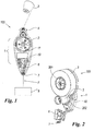
- this shows a constant tension yarn feeder operating by over end takeoff and acting on the yarn by the method of the present invention.
- the device under examination comprises a body 1 carrying a rotary member or wheel 2 (operated in known manner by its own electrical actuator, not shown) acting on a yarn F unwinding from a bobbin 3.
- a rotary member or wheel 2 acting on a yarn F unwinding from a bobbin 3.
- the yarn F passes through an entry yarn guide 4, for example of ceramic, and is then wound for one or two turns onto said wheel. From this latter the yarn F arrives, in its movement towards the processing machine, which in the example is a textile machine 9, at a sensor member 6 which measures its tension (for example a load cell), and from there it reaches an exit yarn guide 7 (for example of ceramic).
- the rotation of the wheel 2 is controlled by a control member or unit 10 to which the member or load cell 6 measuring the yarn tension is also connected.
- the angle that the yarn assumes (triangulation) on the sensor member or load cell 6 is constant as the stages in the feed of the yarn F to the machine 9 vary; this enables this member or cell 6 to measure the yarn tension during these stages with absolute precision.
- any yarn requirement by this latter results in an increase in the tension of the yarn (withdrawn by the machine on leaving the device), which is measured by the sensor member or cell 6.
- This increase is processed by the control member or unit 10 which intervenes on the rotary member or wheel 2 to vary its velocity in order to maintain the tension constant.
- the device hence operates as a classical closed loop control system, well known to the expert of the art.
- this shows a constant tension yarn feeder 200 operating by rolling takeoff in accordance with the method of the present invention.
- parts identical with or corresponding to those of Figure 1 are indicated by the same reference numerals.
- the device 200 comprises a body 1 supporting a rotary member or wheel 2 (also of cylindrical shape) with which a bobbin 3 is in contact, from which the yarn F unwinds.
- the bobbin 3 is drawn onto an idle shaft 201 supported by the body 1 and is always in contact with the wheel 2.
- a spring (not shown) or equivalent elastic pulling element acts on the shaft 201 and tends to pull it towards the wheel 2; hence whatever the quantity of yarn F on the bobbin 3, this is always in contact with the wheel or rotary member 2.
- the body 1 supports, projecting from it, a tension sensor member or load cell 6, in proximity to which there is an exit yarn guide 7.
- a further entry yarn guide (not visible in the figure) directs the yarn F onto the wheel 2 where it can form a fraction of a turn or several turns.
- the sensor or cell 6 and the wheel 2 are connected to a control unit 10.
- the triangulation on the load cell 6 is constant as the stages in the yarn feed to the textile machine vary, this enabling this load cell to measure the yarn tension during the process stages with absolute precision.
- any yarn requirement by this latter is sensed by the load cell 6 as an increase in tension, the resultant signal being processed by the control unit 10 which varies the velocity of an actuator 202 for the wheel connected to it in order to maintain the tension constant by operating as a classical closed loop control system.
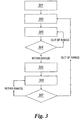
- the flow diagram of Figure 3 describes the method of the present invention, by which the feed is able to pass from constant tension feed to constant velocity feed (absorbed yarn length) totally automatically. This method is implemented equally both for the device 100 of Figure 1 and the device 200 of Figure 2 by the unit 10 which controls the corresponding rotary members 2.
- the device 100 or 200 is in the start-up stage during which initialization takes place of all operating variables stored in a memory of the unit 10, preferably of microprocessor type.
- the procedure automatically passes to the block 302.
- tension control is activated followed by direct automatic passage to the stage of block 303.
- the actuator of the member 5 is controlled by the control unit 10 to maintain the tension of the yarn F equal to a constant value by increasing its velocity (and that of the corresponding member 5) if the tension read by the sensor member 6 is higher than a set value or reducing its velocity if the read tension is lower than the set value, using for example a known PID algorithm.
- the feeder device 100 or 200 is hence able to commence feeding the yarn F as soon as the machine 9 starts to require it (sensed by the device as an increase in the tension measured by the sensor member 6 relative to its set-point value) and to halt the feed as soon as this requirement ceases (sensed by a decrease in the measured tension relative to its set-point value). All this is achieved completely automatically without the need for any synchronization with the machine.
- the yarn feed velocity is also measured by the sensor 11, which could be at least one Hall sensor or encoder, possibly integrated into the actuator associated with the rotary member 2.
- a tension check is carried out (block 304).
- the device unit 10 continues to monitor the tension read by the member 6 to check whether this lies within a possibly programmed range (for example ⁇ 5% of the set-point tension) for a predetermined time (also possibly programmable). If the tension lies outside this range, the unit 5 continues to operate in the yarn constant tension control mode of operation by automatically returning to block 303. If however the "tension within range" condition is verified (measured tension within the desired range), the procedure automatically passes to block 305 after memorizing the feed velocity value (possibly filtered or mediated) at that instant, which becomes the set-point velocity. In this stage the unit 10 activates velocity control and passes directly to block 306 in which the actuator of the member 2, controlled by this control unit 10 to maintain the velocity of the member 2 constant, makes it equal to the self-taught value.
- a possibly programmed range for example ⁇ 5% of the set-point tension
- a predetermined time also possibly programmable
- the control unit 10 then closes its PID loop no longer on the basis of the tension but on the basis of the actuator velocity. During this control the unit 5 also measures the yarn tension and performs the operation represented by block 307.
- control unit 10 continues to monitor the read tension to verify whether this lies within a possibly programmed range (for example ⁇ 5% of the set-point tension) for a predetermined time (possibly programmable). If the tension lies within this range, the unit 5 continues to operate in the constant feed velocity control mode of operation by automatically returning to block 306. If however the condition is verified in which the tension lies outside the range, the procedure automatically returns to block 302.
- a possibly programmed range for example ⁇ 5% of the set-point tension
- a predetermined time possibly programmable
- control unit 10 during constant velocity yarn feed, is able to monitor the tension not only to verify that this continues to remain within a predetermined range, but also to verify its mean variation to check whether it remains equal to the set tension and if necessary act on the velocity set-point to achieve this equality.
- the unit 10 is able to halt the machine 9 if the mean tension continues to deviate from the set value with time, notwithstanding a predetermined number of tension correction attempts obtained by acting on the member 2. This could in fact be caused by an accumulation of dirt in the machine yarn guide or by a loss of mechanical calibration of the members provided for stitch formation in the textile machine.
- the control unit is able to monitor the variation in the instantaneous tension and determine whether this changes suddenly with time, with consequent sensing that the textile machine yarn withdrawal is not continuous but discontinuous (jacquard application). In that case even if the tension is within the range of predetermined values, the unit 10 automatically passes to the constant tension feed mode for the yarn F, which ensures greater quality in the case of discontinuous applications.
- the control unit 10 is not only able to monitor the tension variation to verify whether it is or is not within a predetermined range, but is able simultaneously to verify the velocity variation of the wheel 2. If this velocity is not constant but varies suddenly with time, this means that the textile machine yarn withdrawal is not continuous but discontinuous (jacquard application). In that case the unit may decide not to pass to the constant velocity yarn feed mode even though the tension is within the range, to ensure greater quality.
- control unit can have as its reference set-point not the value self-learnt at the moment of passage from the constant tension mode to the constant velocity mode, but instead a predetermined and/or programmed and/or calculated value (for example the mean of the velocity of one or more devices) in order to make the absorbed yarn lengths of several similar devices operating on corresponding yarns fed to the same machine 9 uniform at the same value, for example for the purpose of causing all those feeders which cooperate with the same yarn type or which carry out the same type of production to operate at the same velocity.
- a predetermined and/or programmed and/or calculated value for example the mean of the velocity of one or more devices
- the devices could operate in a configuration of MASTER-SLAVE type in which, for each type of yarn or production, only one of the devices is MASTER (MASTER_1, MASTER_2, MASTER_n, and all the others are SLAVE (SLAVE_1, SLAVE_2, SLAVE_n); hence in this case the MASTER would determine the feed velocity of all associated slave devices.
- a system for feeding a plurality of yarns to a textile machine, each yarn F being fed by an aforesaid feed device in accordance with the previously described method, in which the value of the yarn length absorbed by said devices is made uniform for at least part of these latter at the same value; these devices operate in master-slave configuration in which for each yarn type or production type only one of these devices is master while the others are slaves, said master device determining the feed velocity of all the associated slave devices. All the associated devices operate on yarns of the same type, with all the associated devices carrying out the same type of production.
- This expedient further increases product quality without requiring any synchronization with the machine; in this respect by constantly monitoring the yarn tension and the pulley velocity, the unit 10 can ensure yarn feed even in the case in which for example the indicated set-point is in fact mistaken, imagining for example having programmed a velocity value double that required; the unit 10, on measuring the tension, realizes that this is outside the range and automatically passes to the constant tension mode, possibly indicating the irregularity to a supervision unit or halting the machine.
- the unit 10 could also use different ranges (in percentage terms) and/or different filters, and could use for example an average measured tension value rather than the instantaneous value to decide when this is within or outside the range to verify the variation in the controlled tension value in relation to the predetermined value range in order to accelerate or decelerate passage from one operating mode to the other, to optimize the process.
- control device could be totally integrated into the electronic system controlling the machine (or if external to this electronic system it could communicate with it via a communication bus, for example) which, knowing the type of manufacture under way, can hence directly pass to the device the operating mode (constant tension or constant velocity), and also possibly the velocity at which the device has to feed the yarn to the machine.
Landscapes
- Engineering & Computer Science (AREA)
- Textile Engineering (AREA)
- Tension Adjustment In Filamentary Materials (AREA)
- Looms (AREA)
- Knitting Machines (AREA)
Claims (13)
- Verfahren zur Fadenlieferung an eine Verarbeitungsmaschine, wie zum Beispiel eine Textilmaschine, eine Metalldrahtverarbeitungsmaschine oder ähnliche Fadenverarbeitungsmaschine, wobei das genannte Verfahren daraus besteht, dass der Faden (F) von einer Spule (3) abgespult wird, dass der Faden zur Zusammenwirkung mit einem Drehelement (2) gebracht wird, und dass er daraus bis zu einem Fühlerelement geführt wird, wobei das Fühlerelement angeordnet ist, um die Spannung der Fadenlieferung an die Verarbeitungsmaschine (9) und/oder der Fadenrücknahme von der Verarbeitungsmaschine (9) zu überprüfen, wobei die Drehgeschwindigkeit des Drehelements (2) und deswegen die Lieferungsgeschwindigkeit an die genannte Maschine überwacht werden, wobei das genannte Element (2) durch seinen eigenen Aktor (202) getrieben wird, wobei die Daten der gemessenen Spannung und der gemessenen Geschwindigkeit an eine die Fadenlieferung an die Maschine steuernde Steuerungseinheit (10) übertragen werden, wobei das Verfahren das folgende umfasst: 1) ständige Steuerung der Spannung durch die genannte Einheit (10), um die Spannung mindestens in einem Bereich von konstanten Werten zu halten; 2) wenn dieser Spannungszustand bestätigt wird, Steuerung der Fadenlieferungsgeschwindigkeit und somit die Menge oder Länge des an die Maschine gelieferten Fadens (F), um sie konstant und einem selbstbestimmten oder vorgegebenen und programmierbaren Wert entsprechend zu halten; 3) bei konstanter Geschwindigkeit, wird der Spannungswert ständig überprüft, um zu bestätigen, dass er in einem Bereich von konstanten Werten bleibt, wobei diese Steuerung der Fadenlieferung an die Verarbeitungsmaschine (9) mit konstanter Spannung und konstanter Geschwindigkeit entweder mit oder ohne Synchronisierung mit der genannten Maschine durchgeführt wird, dadurch gekennzeichnet, dass, als die Spannung einen Wert außerhalb dieses Bereichs annimmt, die Spannung einem neuen Steuerungsverfahren unterliegt, um sie innerhalb des genannten Bereichs von konstanten Werten wiederzubringen, wobei das genannte Steuerungsverfahren von der Steuerung der Geschwindigkeit, um sie konstant zu halten, nochmals gefolgt ist.
- Verfahren nach Anspruch 1, dadurch gekennzeichnet, dass bei konstanter Fadenlieferungsgeschwindigkeit der Spannungswert bewertet wird, wobei er mit dem genannten vorbestimmten Bereich von Spannungswerten verglichen wird und, wenn der genannte Mittelwert außerhalb dieses Bereichs liegt, die Geschwindigkeit des Drehelements (2) geändert wird, so dass die Spannung zu dem gewünschten Mittelwert gebracht werden kann, und die Verarbeitungsmaschine (9) abgestellt wird wenn, nach einer vorbestimmten Zahl von Korrekturversuchen, die Spannung den gewünschten Wert nicht erzielt.
- Verfahren nach Anspruch 1, dadurch gekennzeichnet, dass bei konstanter Fadenlieferungsgeschwindigkeit die Spannungsmomentanwert überwacht wird, um festzustellen, ob die Spannung plötzlich mit der Zeit ändert, wobei eine solche Feststellung der Änderung ermöglicht die Steuerungseinheit (10), eine diskontinuierliche Lieferung des Fadens (F) an die Verarbeitungsmaschine (9); in diesem Fall übergeht die Lieferungssteuerung der genannten Einheit (10) von der Steuerung der Lieferung mit konstanter Geschwindigkeit zu der Steuerung der Lieferung mit konstanter Spannung, um diese Spannung bei der diskontinuierlichen Fadenlieferung innerhalb eines Bereichs von vorbestimmten Werten gehalten wird.
- Verfahren nach Anspruch 1, dadurch gekennzeichnet, dass bei konstanter Fadenlieferungsspannung die Drehgeschwindigkeit des Drehelements (2) ständig überwacht wird und, wenn diese Geschwindigkeit plötzlich mit der Zeit ändert, die Steuerungseinheit (10) das Bestehen einer diskontinuierlichen Fadenlieferung feststellt und eine Steuerung der Fadenlieferung mit konstanter Spannung hält, um die Spannung konstant zu halten.
- Verfahren nach Anspruch 1, dadurch gekennzeichnet, dass der Bereich von Spannungswerten, mit denen die Spannung des Fadens (F) bei der Lieferung an die Verarbeitungsmaschine (9) verglichen wird, derart gewählt wird, dass die absorbierte Fadenlänge dieselbe für eine Vielzahl von an die genannte Maschine gelieferten Fäden ist.
- Verfahren nach Anspruch 1, dadurch gekennzeichnet, dass der Bereich von konstanten Spannungswerten, mit denen bei konstant gehaltenen Geschwindigkeit die Spannung verglichen wird, während der Herstellung eines und desselben Artikels unverändert bleibt oder alternativ nach dem ersten Vergleich mit einem ersten Bereich von Werten ändert.
- Verfahren nach Anspruch 1, dadurch gekennzeichnet, dass der Bereich von konstanten Spannungswerten, mit denen die Spannung des Fadens (F) bei der Lieferung an die Textilmaschine verglichen wird, während der Herstellung eines und desselben Artikels je nach der Bildung von verschiedenen Teilen davon ändert.
- Vorrichtung zur Lieferung eines Fadens (F) an eine Verarbeitungsmaschine, wie zum Beispiel eine Textilmaschine (9), eine Metalldrahtverarbeitungsmaschine oder ähnliche Maschine, die sich eignet, den genannten Faden (F) von einer Spule (3) abzuspulen und mit einem Drehelement (2) und danach mit einem Fühlerlement zusammenzuwirken, wobei das Fühlerelement angeordnet ist, um die Spannung der Fadenlieferung an die Verarbeitungsmaschine (9) und/oder der Fadenrücknahme von der Verarbeitungsmaschine (9) zu überprüfen, mit Mitteln (10) zur Überwachung der Drehgeschwindigkeit des Drehelements (2), wobei dieses durch seinen eigenen Aktor (202) getrieben wird, wobei der Aktor fähig ist, die Daten der gemessenen Spannung und der gemessenen Geschwindigkeit an eine die Fadenlieferung an die Maschine steuernde Steuerungseinheit (10) übertragen werden, dadurch gekennzeichnet, dass sie nach dem Verfahren nach Anspruch 1 funktioniert.
- Vorrichtung nach Anspruch 8, dadurch gekennzeichnet, dass sie eine Fadenliefervorrichtung ist, die auf den Faden (F) einwirkt, indem sie ihn durch "Overend-Takeoff" von der Spule (3) abspult.
- Vorrichtung nach Anspruch 8, dadurch gekennzeichnet, dass sie eine Fadenliefervorrichtung ist, die auf den Faden (F) einwirkt, indem sie ihn durch "Rolling-Takeoff" abspult, wobei die genannte Fadenliefervorrichtung einen Körper (1) umfasst, der ein Drehelement (2) trägt, das in Berührung mit der auf einer Welle (201) gezogenen Spule (3) steht, wobei die Welle (201) mit dem genannten Körper (1) fest verbunden ist und einem Zugelement unterworfen ist, das sie dem genannten Drehelement näher verschiebt, wobei der genannte Körper (1) einen Spannungsfühler für den Faden (F) trägt.
- System zur Lieferung einer Vielzahl von Fäden (F) an eine Textilmaschine, wobei jeder Faden (F) durch eine Vorrichtung nach Anspruch 8 durch das Verfahren nach Anspruch 1 geliefert wird, dadurch gekennzeichnet, dass der Wert der durch die genannten, die genannten Fäden liefernden Vorrichtungen absorbierten Fadenlänge für mindestens einen Teil der genannten Fäden auf denselben Wert vereinheitlicht wird.
- System nach Anspruch 11, dadurch gekennzeichnet, dass die genannten Vorrichtungen in Master-Slave Anordnung ausgebildet sind, worin für jeder Fadentyp oder Herstellungstyp nur eine von diesen Vorrichtung Master ist, die anderen sind dagegen Slaves, wobei die genannte Master-Vorrichtung die Lieferungsgeschwindigkeit der Gesamtheit der zugehörigen Slave-Vorrichtungen bestimmt.
- System nach Anspruch 11, dadurch gekennzeichnet, dass die Gesamtheit der zugehörigen Vorrichtungen auf denselben Typ von Fäden einwirkt, wobei die Gesamtheit der zugehörigen Vorrichtungen denselben Typ von Herstellung erledigt.
Applications Claiming Priority (2)
| Application Number | Priority Date | Filing Date | Title |
|---|---|---|---|
| IT000887A ITMI20100887A1 (it) | 2010-05-18 | 2010-05-18 | Metodo e dispositivo perfezionato per alimentare un filo ad una macchina operatrice con tensione e velocita' costante |
| PCT/IB2011/001072 WO2011144987A2 (en) | 2010-05-18 | 2011-05-17 | Improved method and device for feeding a yarn or thread to a processing machine with constant tension and velocity |
Publications (2)
| Publication Number | Publication Date |
|---|---|
| EP2572023A2 EP2572023A2 (de) | 2013-03-27 |
| EP2572023B1 true EP2572023B1 (de) | 2017-10-04 |
Family
ID=43740704
Family Applications (1)
| Application Number | Title | Priority Date | Filing Date |
|---|---|---|---|
| EP11769916.5A Active EP2572023B1 (de) | 2010-05-18 | 2011-05-17 | Verbessertes verfahren und vorrichtung zur fadenlieferung mit konstanter spannung und geschwindigkeit an eine verarbeitungsmaschine |
Country Status (7)
| Country | Link |
|---|---|
| US (1) | US9181064B2 (de) |
| EP (1) | EP2572023B1 (de) |
| JP (1) | JP6002125B2 (de) |
| CN (1) | CN102884234B (de) |
| ES (1) | ES2655118T3 (de) |
| IT (1) | ITMI20100887A1 (de) |
| WO (1) | WO2011144987A2 (de) |
Cited By (1)
| Publication number | Priority date | Publication date | Assignee | Title |
|---|---|---|---|---|
| IT202100017966A1 (it) | 2021-07-08 | 2023-01-08 | Lgl Electronics Spa | Alimentatore di filato positivo motorizzato con modalità operativa selezionabile, ed apparato di alimentazione di filato utilizzante lo stesso. |
Families Citing this family (26)
| Publication number | Priority date | Publication date | Assignee | Title |
|---|---|---|---|---|
| ITMI20111027A1 (it) * | 2011-06-08 | 2012-12-09 | Btsr Int Spa | Metodo e dispositivo per alimentare a tensione e velocita' o quantita' costante un filo ad una macchina tessile |
| ITMI20121846A1 (it) | 2012-10-30 | 2014-05-01 | Btsr Int Spa | Metodo e sistema per alimentare a tensione costante e stiro prestabilito un filo ad una macchina tessile in funzione della fase operativa di quest'ultima |
| ITTO20130017A1 (it) * | 2013-01-10 | 2014-07-11 | Lgl Electronics Spa | Gruppo di alimentazione di filato per macchine tessili. |
| CN107881607B (zh) * | 2013-04-03 | 2020-10-16 | 英威达技术有限公司 | 对弹力纱线进给的牵伸控制的过程 |
| EP3103749B1 (de) * | 2015-06-12 | 2019-12-04 | L.G.L. Electronics S.p.A. | Verfahren zur steuerung der abnutzungsrate eines garns, der von einem anhäufungszuführer an eine textilmaschine abgewickelt wird, und vorrichtung zur ausführung eines solchen verfahrens |
| BE1023220B1 (nl) * | 2015-07-03 | 2017-01-03 | Nv Michel Van De Wiele | Aanvoerinrichting voor aanvoeren van garens, werkwijze voor het bepalen van de spanning van garens en gebruik van controlemiddelen voor het aansturen van actuatoren voor het aanvoeren van garens |
| ITUB20152769A1 (it) * | 2015-08-03 | 2017-02-03 | Btsr Int Spa | Alimentatore di filo ad accumulo con organo frenante e elementi intercambiabili |
| USD794683S1 (en) * | 2015-09-15 | 2017-08-15 | Btsr International S.P.A. | Yarn feeder |
| USD794715S1 (en) * | 2015-09-15 | 2017-08-15 | Btsr International S.P.A. | Yarn feeder |
| CN105603625A (zh) * | 2015-12-30 | 2016-05-25 | 楼春桦 | 一种纱线给进器 |
| CN106350930B (zh) * | 2016-11-30 | 2018-02-02 | 广西大学 | 一种针织机恒张力输纱装置 |
| IT201700113434A1 (it) * | 2017-10-10 | 2019-04-10 | Lgl Electronics Spa | Metodo di controllo del consumo di filato in un processo di tessitura |
| DE102017128327B3 (de) | 2017-11-29 | 2019-01-10 | Memminger-Iro Gmbh | Verfahren zur Steuerung der Lieferung von Fäden eines Systems mit mehreren Fadenliefergeräten und Textilmaschine mit einem System mit mehreren Fadenliefergeräten |
| EP3728713B1 (de) * | 2017-12-22 | 2023-08-23 | Compagnie Generale Des Etablissements Michelin | Vefahren und anlage zum verdrehen von reifenkorde mit kontrollierter spannung |
| IT201800002452A1 (it) * | 2018-02-06 | 2019-08-06 | Btsr Int Spa | Metodo, sistema alimentatore di filo perfezionato e dispositivo per ottimizzare l'alimentazione di filo ad una macchina tessile operante con elevata discontinuita' o con un moto alternato |
| USD892178S1 (en) * | 2018-02-13 | 2020-08-04 | Spin Master Ltd. | Braiding device |
| USD894973S1 (en) * | 2018-02-13 | 2020-09-01 | Spin Master Ltd. | Braiding device |
| JP7048407B2 (ja) * | 2018-05-11 | 2022-04-05 | 株式会社島精機製作所 | 編機の張力測定装置及びその張力測定方法 |
| IT201900011451A1 (it) * | 2019-07-11 | 2021-01-11 | Lgl Electronics Spa | Metodo per l'alimentazione a tensione controllata di una pluralita' di filati ad una macchina tessile |
| CN110820157B (zh) * | 2019-10-31 | 2021-08-10 | 宁波慈星股份有限公司 | 一种针织机的智能恒张力送纱方法 |
| JP7510323B2 (ja) * | 2020-10-08 | 2024-07-03 | 株式会社ジャノメ | ミシン及びその刺繍縫製方法並びに刺繍縫製プログラム |
| JP7762575B2 (ja) * | 2021-01-26 | 2025-10-30 | Tmtマシナリー株式会社 | 糸加工設備 |
| EP4474326B1 (de) * | 2023-06-07 | 2026-04-15 | Eltex of Sweden AB | Selbstsynchronisierendes system zur überwachung und steuerung der fadenspannung |
| EP4474325B1 (de) * | 2023-06-07 | 2026-01-14 | Eltex of Sweden AB | Selbstsynchronisierendes system zur überwachung und steuerung der fadenspannung |
| CN117214199B (zh) * | 2023-11-08 | 2024-02-09 | 张家港扬子纺纱有限公司 | 一种纱线毛羽检测装置及检测系统 |
| CN121700591A (zh) * | 2026-02-14 | 2026-03-20 | 张家港牧羊人服饰有限公司 | 基于多参数协同控制的羊毛针织面料制备方法 |
Family Cites Families (15)
| Publication number | Priority date | Publication date | Assignee | Title |
|---|---|---|---|---|
| JPS5925505A (ja) | 1982-07-30 | 1984-02-09 | 株式会社フジクラ | 延線車の制動制御方式 |
| JPH0699063B2 (ja) * | 1985-01-30 | 1994-12-07 | 株式会社日立製作所 | 慣性張力補償巻取繰出し装置 |
| DE3627731C1 (de) * | 1986-08-16 | 1988-03-31 | Gustav Memminger | Fadenliefervorrichtung mit elektronischer Fadenspannungsregelung |
| DE19544202B4 (de) * | 1995-11-28 | 2007-01-04 | Saurer Gmbh & Co. Kg | Verfahren und Vorrichtung zum Einregeln einer nach einem Rechenspanner vorliegenden Fadenzugkraft in einer Textilmaschine |
| JP3201325B2 (ja) | 1997-12-25 | 2001-08-20 | 村田機械株式会社 | 自動ワインダー |
| DE19811241A1 (de) * | 1998-03-14 | 1999-09-30 | Memminger Iro Gmbh | Fadenspannungssensor mit wiederholtem Abgleich |
| IT1303022B1 (it) * | 1998-04-17 | 2000-10-20 | Btsr Int Spa | Dispositivo di controllo dell'alimentazione del filato ad una macchinatessile e metodo di controllo del funzionamento e produzione di |
| EP1125880A3 (de) | 2000-02-17 | 2002-08-28 | Schärer Schweiter Mettler AG | Vorrichtung zur Herstellung von Spulen auf einer OE-Spinnmaschine |
| DE10032705B4 (de) | 2000-07-05 | 2006-11-16 | Memminger-Iro Gmbh | Fadenliefereinrichtung für Textilmaschinen |
| US6676054B2 (en) * | 2001-03-23 | 2004-01-13 | E. I. Du Pont De Nemours And Company | Unwinder for as-spun elastomeric fiber |
| ITMI20020770A1 (it) * | 2002-04-10 | 2003-10-10 | Tiziano Barea | Dispositivo e metodo per alimentare un filo elastomerico ad una macchina tessile al fine di avere un manufatto di qualita' costante in ogni |
| DE10234545B4 (de) * | 2002-07-30 | 2005-12-15 | Memminger-Iro Gmbh | Verfahren und Vorrichtung zum Liefern von Fäden |
| ITFI20040113A1 (it) | 2004-05-14 | 2004-08-13 | Giovanni Corsani | Dispositivo alimentatore di filo |
| JP2006225051A (ja) | 2005-02-15 | 2006-08-31 | Nittoku Eng Co Ltd | テンション監視装置 |
| ITMI20051325A1 (it) * | 2005-07-12 | 2007-01-13 | Btsr Int Spa | Metodo e dispositivo per assicurare l'alimentazione di un filo a tensione costante a doppio anello di regolazione ad una macchina tessile |
-
2010
- 2010-05-18 IT IT000887A patent/ITMI20100887A1/it unknown
-
2011
- 2011-05-17 JP JP2013510690A patent/JP6002125B2/ja active Active
- 2011-05-17 EP EP11769916.5A patent/EP2572023B1/de active Active
- 2011-05-17 WO PCT/IB2011/001072 patent/WO2011144987A2/en not_active Ceased
- 2011-05-17 ES ES11769916.5T patent/ES2655118T3/es active Active
- 2011-05-17 CN CN201180022011.4A patent/CN102884234B/zh active Active
- 2011-05-17 US US13/640,359 patent/US9181064B2/en active Active
Non-Patent Citations (1)
| Title |
|---|
| None * |
Cited By (2)
| Publication number | Priority date | Publication date | Assignee | Title |
|---|---|---|---|---|
| IT202100017966A1 (it) | 2021-07-08 | 2023-01-08 | Lgl Electronics Spa | Alimentatore di filato positivo motorizzato con modalità operativa selezionabile, ed apparato di alimentazione di filato utilizzante lo stesso. |
| EP4116476A1 (de) | 2021-07-08 | 2023-01-11 | L.G.L. Electronics S.p.A. | Motorisierter positiver fadenzuführer mit wählbarem betriebsmodus und fadenzuführungsvorrichtung damit |
Also Published As
| Publication number | Publication date |
|---|---|
| CN102884234A (zh) | 2013-01-16 |
| JP2013530904A (ja) | 2013-08-01 |
| ITMI20100887A1 (it) | 2011-11-19 |
| ES2655118T3 (es) | 2018-02-16 |
| WO2011144987A3 (en) | 2012-04-19 |
| CN102884234B (zh) | 2014-10-29 |
| US9181064B2 (en) | 2015-11-10 |
| WO2011144987A2 (en) | 2011-11-24 |
| JP6002125B2 (ja) | 2016-10-05 |
| EP2572023A2 (de) | 2013-03-27 |
| US20130056573A1 (en) | 2013-03-07 |
Similar Documents
| Publication | Publication Date | Title |
|---|---|---|
| EP2572023B1 (de) | Verbessertes verfahren und vorrichtung zur fadenlieferung mit konstanter spannung und geschwindigkeit an eine verarbeitungsmaschine | |
| EP2067886B1 (de) | Verfahren und Vorrichtung zur Lieferung eines Garns mit einer konstanten aufgenommenen Länge für eine Textilmaschine, die mit mehreren Garnen arbeitet | |
| CN100434585C (zh) | 用于将弹性纱喂入纺织机的装置和方法 | |
| JP4637981B2 (ja) | 繊維機械と、繊維機械に供給する糸の供給を制御する装置とからなる構成 | |
| JP6002214B2 (ja) | 一定の張力と一定の速度又は量で糸を繊維機械に供給する方法及び装置 | |
| EP2218809B1 (de) | Verfahren und system zur fadenspannungskonstanten fadenlieferung oder -rückspulung eines zu einer textilmaschine gelieferten garnes, sowie eine textilmaschine, welche das verfahren oder system verwendet | |
| EP2914524B1 (de) | Verfahren und system zum beliefern eines fadens in eine textilmaschine mit konstanter spannung und vorgegebenem zug als funktion eines betriebsschrittes dieser maschine | |
| JP2009173445A5 (de) | ||
| WO2014165616A1 (en) | Process for draft control on feeding of elastic yarn | |
| KR101520525B1 (ko) | 니트웨어 또는 양말류용 환편기에서 생산하는 편직 물품들의 크기를 조절하기 위한 공정 | |
| KR100641681B1 (ko) | 와인더의 권취장력 조절방법 및 조절시스템 |
Legal Events
| Date | Code | Title | Description |
|---|---|---|---|
| PUAI | Public reference made under article 153(3) epc to a published international application that has entered the european phase |
Free format text: ORIGINAL CODE: 0009012 |
|
| 17P | Request for examination filed |
Effective date: 20121018 |
|
| AK | Designated contracting states |
Kind code of ref document: A2 Designated state(s): AL AT BE BG CH CY CZ DE DK EE ES FI FR GB GR HR HU IE IS IT LI LT LU LV MC MK MT NL NO PL PT RO RS SE SI SK SM TR |
|
| DAX | Request for extension of the european patent (deleted) | ||
| GRAP | Despatch of communication of intention to grant a patent |
Free format text: ORIGINAL CODE: EPIDOSNIGR1 |
|
| STAA | Information on the status of an ep patent application or granted ep patent |
Free format text: STATUS: GRANT OF PATENT IS INTENDED |
|
| INTG | Intention to grant announced |
Effective date: 20170502 |
|
| GRAA | (expected) grant |
Free format text: ORIGINAL CODE: 0009210 |
|
| GRAS | Grant fee paid |
Free format text: ORIGINAL CODE: EPIDOSNIGR3 |
|
| STAA | Information on the status of an ep patent application or granted ep patent |
Free format text: STATUS: THE PATENT HAS BEEN GRANTED |
|
| AK | Designated contracting states |
Kind code of ref document: B1 Designated state(s): AL AT BE BG CH CY CZ DE DK EE ES FI FR GB GR HR HU IE IS IT LI LT LU LV MC MK MT NL NO PL PT RO RS SE SI SK SM TR |
|
| REG | Reference to a national code |
Ref country code: GB Ref legal event code: FG4D |
|
| REG | Reference to a national code |
Ref country code: CH Ref legal event code: EP |
|
| REG | Reference to a national code |
Ref country code: AT Ref legal event code: REF Ref document number: 934139 Country of ref document: AT Kind code of ref document: T Effective date: 20171015 |
|
| REG | Reference to a national code |
Ref country code: IE Ref legal event code: FG4D |
|
| REG | Reference to a national code |
Ref country code: DE Ref legal event code: R096 Ref document number: 602011042129 Country of ref document: DE |
|
| REG | Reference to a national code |
Ref country code: CH Ref legal event code: NV Representative=s name: R.A. EGLI AND CO, PATENTANWAELTE, CH |
|
| REG | Reference to a national code |
Ref country code: SE Ref legal event code: TRGR |
|
| REG | Reference to a national code |
Ref country code: NL Ref legal event code: MP Effective date: 20171004 |
|
| REG | Reference to a national code |
Ref country code: ES Ref legal event code: FG2A Ref document number: 2655118 Country of ref document: ES Kind code of ref document: T3 Effective date: 20180216 |
|
| REG | Reference to a national code |
Ref country code: LT Ref legal event code: MG4D |
|
| REG | Reference to a national code |
Ref country code: AT Ref legal event code: MK05 Ref document number: 934139 Country of ref document: AT Kind code of ref document: T Effective date: 20171004 |
|
| REG | Reference to a national code |
Ref country code: FR Ref legal event code: PLFP Year of fee payment: 8 |
|
| PG25 | Lapsed in a contracting state [announced via postgrant information from national office to epo] |
Ref country code: NL Free format text: LAPSE BECAUSE OF FAILURE TO SUBMIT A TRANSLATION OF THE DESCRIPTION OR TO PAY THE FEE WITHIN THE PRESCRIBED TIME-LIMIT Effective date: 20171004 |
|
| PG25 | Lapsed in a contracting state [announced via postgrant information from national office to epo] |
Ref country code: NO Free format text: LAPSE BECAUSE OF FAILURE TO SUBMIT A TRANSLATION OF THE DESCRIPTION OR TO PAY THE FEE WITHIN THE PRESCRIBED TIME-LIMIT Effective date: 20180104 Ref country code: LT Free format text: LAPSE BECAUSE OF FAILURE TO SUBMIT A TRANSLATION OF THE DESCRIPTION OR TO PAY THE FEE WITHIN THE PRESCRIBED TIME-LIMIT Effective date: 20171004 Ref country code: FI Free format text: LAPSE BECAUSE OF FAILURE TO SUBMIT A TRANSLATION OF THE DESCRIPTION OR TO PAY THE FEE WITHIN THE PRESCRIBED TIME-LIMIT Effective date: 20171004 |
|
| PG25 | Lapsed in a contracting state [announced via postgrant information from national office to epo] |
Ref country code: IS Free format text: LAPSE BECAUSE OF FAILURE TO SUBMIT A TRANSLATION OF THE DESCRIPTION OR TO PAY THE FEE WITHIN THE PRESCRIBED TIME-LIMIT Effective date: 20180204 Ref country code: HR Free format text: LAPSE BECAUSE OF FAILURE TO SUBMIT A TRANSLATION OF THE DESCRIPTION OR TO PAY THE FEE WITHIN THE PRESCRIBED TIME-LIMIT Effective date: 20171004 Ref country code: GR Free format text: LAPSE BECAUSE OF FAILURE TO SUBMIT A TRANSLATION OF THE DESCRIPTION OR TO PAY THE FEE WITHIN THE PRESCRIBED TIME-LIMIT Effective date: 20180105 Ref country code: LV Free format text: LAPSE BECAUSE OF FAILURE TO SUBMIT A TRANSLATION OF THE DESCRIPTION OR TO PAY THE FEE WITHIN THE PRESCRIBED TIME-LIMIT Effective date: 20171004 Ref country code: AT Free format text: LAPSE BECAUSE OF FAILURE TO SUBMIT A TRANSLATION OF THE DESCRIPTION OR TO PAY THE FEE WITHIN THE PRESCRIBED TIME-LIMIT Effective date: 20171004 Ref country code: BG Free format text: LAPSE BECAUSE OF FAILURE TO SUBMIT A TRANSLATION OF THE DESCRIPTION OR TO PAY THE FEE WITHIN THE PRESCRIBED TIME-LIMIT Effective date: 20180104 Ref country code: RS Free format text: LAPSE BECAUSE OF FAILURE TO SUBMIT A TRANSLATION OF THE DESCRIPTION OR TO PAY THE FEE WITHIN THE PRESCRIBED TIME-LIMIT Effective date: 20171004 |
|
| REG | Reference to a national code |
Ref country code: DE Ref legal event code: R097 Ref document number: 602011042129 Country of ref document: DE |
|
| PG25 | Lapsed in a contracting state [announced via postgrant information from national office to epo] |
Ref country code: DK Free format text: LAPSE BECAUSE OF FAILURE TO SUBMIT A TRANSLATION OF THE DESCRIPTION OR TO PAY THE FEE WITHIN THE PRESCRIBED TIME-LIMIT Effective date: 20171004 Ref country code: SK Free format text: LAPSE BECAUSE OF FAILURE TO SUBMIT A TRANSLATION OF THE DESCRIPTION OR TO PAY THE FEE WITHIN THE PRESCRIBED TIME-LIMIT Effective date: 20171004 Ref country code: EE Free format text: LAPSE BECAUSE OF FAILURE TO SUBMIT A TRANSLATION OF THE DESCRIPTION OR TO PAY THE FEE WITHIN THE PRESCRIBED TIME-LIMIT Effective date: 20171004 Ref country code: CZ Free format text: LAPSE BECAUSE OF FAILURE TO SUBMIT A TRANSLATION OF THE DESCRIPTION OR TO PAY THE FEE WITHIN THE PRESCRIBED TIME-LIMIT Effective date: 20171004 |
|
| PLBE | No opposition filed within time limit |
Free format text: ORIGINAL CODE: 0009261 |
|
| STAA | Information on the status of an ep patent application or granted ep patent |
Free format text: STATUS: NO OPPOSITION FILED WITHIN TIME LIMIT |
|
| PG25 | Lapsed in a contracting state [announced via postgrant information from national office to epo] |
Ref country code: IT Free format text: LAPSE BECAUSE OF FAILURE TO SUBMIT A TRANSLATION OF THE DESCRIPTION OR TO PAY THE FEE WITHIN THE PRESCRIBED TIME-LIMIT Effective date: 20171004 Ref country code: PL Free format text: LAPSE BECAUSE OF FAILURE TO SUBMIT A TRANSLATION OF THE DESCRIPTION OR TO PAY THE FEE WITHIN THE PRESCRIBED TIME-LIMIT Effective date: 20171004 Ref country code: SM Free format text: LAPSE BECAUSE OF FAILURE TO SUBMIT A TRANSLATION OF THE DESCRIPTION OR TO PAY THE FEE WITHIN THE PRESCRIBED TIME-LIMIT Effective date: 20171004 Ref country code: RO Free format text: LAPSE BECAUSE OF FAILURE TO SUBMIT A TRANSLATION OF THE DESCRIPTION OR TO PAY THE FEE WITHIN THE PRESCRIBED TIME-LIMIT Effective date: 20171004 |
|
| 26N | No opposition filed |
Effective date: 20180705 |
|
| PG25 | Lapsed in a contracting state [announced via postgrant information from national office to epo] |
Ref country code: SI Free format text: LAPSE BECAUSE OF FAILURE TO SUBMIT A TRANSLATION OF THE DESCRIPTION OR TO PAY THE FEE WITHIN THE PRESCRIBED TIME-LIMIT Effective date: 20171004 |
|
| PG25 | Lapsed in a contracting state [announced via postgrant information from national office to epo] |
Ref country code: MC Free format text: LAPSE BECAUSE OF FAILURE TO SUBMIT A TRANSLATION OF THE DESCRIPTION OR TO PAY THE FEE WITHIN THE PRESCRIBED TIME-LIMIT Effective date: 20171004 |
|
| REG | Reference to a national code |
Ref country code: IE Ref legal event code: MM4A |
|
| PG25 | Lapsed in a contracting state [announced via postgrant information from national office to epo] |
Ref country code: LU Free format text: LAPSE BECAUSE OF NON-PAYMENT OF DUE FEES Effective date: 20180517 |
|
| PG25 | Lapsed in a contracting state [announced via postgrant information from national office to epo] |
Ref country code: IE Free format text: LAPSE BECAUSE OF NON-PAYMENT OF DUE FEES Effective date: 20180517 |
|
| PG25 | Lapsed in a contracting state [announced via postgrant information from national office to epo] |
Ref country code: MT Free format text: LAPSE BECAUSE OF NON-PAYMENT OF DUE FEES Effective date: 20180517 |
|
| PG25 | Lapsed in a contracting state [announced via postgrant information from national office to epo] |
Ref country code: PT Free format text: LAPSE BECAUSE OF FAILURE TO SUBMIT A TRANSLATION OF THE DESCRIPTION OR TO PAY THE FEE WITHIN THE PRESCRIBED TIME-LIMIT Effective date: 20171004 Ref country code: HU Free format text: LAPSE BECAUSE OF FAILURE TO SUBMIT A TRANSLATION OF THE DESCRIPTION OR TO PAY THE FEE WITHIN THE PRESCRIBED TIME-LIMIT; INVALID AB INITIO Effective date: 20110517 |
|
| PG25 | Lapsed in a contracting state [announced via postgrant information from national office to epo] |
Ref country code: MK Free format text: LAPSE BECAUSE OF NON-PAYMENT OF DUE FEES Effective date: 20171004 Ref country code: CY Free format text: LAPSE BECAUSE OF FAILURE TO SUBMIT A TRANSLATION OF THE DESCRIPTION OR TO PAY THE FEE WITHIN THE PRESCRIBED TIME-LIMIT Effective date: 20171004 |
|
| PG25 | Lapsed in a contracting state [announced via postgrant information from national office to epo] |
Ref country code: AL Free format text: LAPSE BECAUSE OF FAILURE TO SUBMIT A TRANSLATION OF THE DESCRIPTION OR TO PAY THE FEE WITHIN THE PRESCRIBED TIME-LIMIT Effective date: 20171004 |
|
| P01 | Opt-out of the competence of the unified patent court (upc) registered |
Effective date: 20230626 |
|
| PGFP | Annual fee paid to national office [announced via postgrant information from national office to epo] |
Ref country code: DE Payment date: 20250529 Year of fee payment: 15 |
|
| PGFP | Annual fee paid to national office [announced via postgrant information from national office to epo] |
Ref country code: GB Payment date: 20250527 Year of fee payment: 15 Ref country code: ES Payment date: 20250602 Year of fee payment: 15 |
|
| PGFP | Annual fee paid to national office [announced via postgrant information from national office to epo] |
Ref country code: BE Payment date: 20250527 Year of fee payment: 15 |
|
| PGFP | Annual fee paid to national office [announced via postgrant information from national office to epo] |
Ref country code: FR Payment date: 20250526 Year of fee payment: 15 |
|
| PGFP | Annual fee paid to national office [announced via postgrant information from national office to epo] |
Ref country code: CH Payment date: 20250601 Year of fee payment: 15 |
|
| PGFP | Annual fee paid to national office [announced via postgrant information from national office to epo] |
Ref country code: TR Payment date: 20250515 Year of fee payment: 15 |
|
| PGFP | Annual fee paid to national office [announced via postgrant information from national office to epo] |
Ref country code: SE Payment date: 20250527 Year of fee payment: 15 |