EP2572833A2 - Procédé de commande d'au moins une grandeur de commande d'un outil ainsi que l'outil - Google Patents
Procédé de commande d'au moins une grandeur de commande d'un outil ainsi que l'outil Download PDFInfo
- Publication number
- EP2572833A2 EP2572833A2 EP12182894A EP12182894A EP2572833A2 EP 2572833 A2 EP2572833 A2 EP 2572833A2 EP 12182894 A EP12182894 A EP 12182894A EP 12182894 A EP12182894 A EP 12182894A EP 2572833 A2 EP2572833 A2 EP 2572833A2
- Authority
- EP
- European Patent Office
- Prior art keywords
- tool
- orientation
- control
- data
- determination unit
- Prior art date
- Legal status (The legal status is an assumption and is not a legal conclusion. Google has not performed a legal analysis and makes no representation as to the accuracy of the status listed.)
- Withdrawn
Links
- 238000000034 method Methods 0.000 title claims description 53
- 238000004891 communication Methods 0.000 claims abstract description 34
- 238000003466 welding Methods 0.000 claims description 54
- 230000005540 biological transmission Effects 0.000 claims description 11
- 230000006870 function Effects 0.000 claims description 9
- 239000000463 material Substances 0.000 claims description 6
- 238000005553 drilling Methods 0.000 claims description 4
- 238000005304 joining Methods 0.000 claims description 4
- 230000007423 decrease Effects 0.000 claims description 3
- 238000003801 milling Methods 0.000 claims description 3
- 238000000576 coating method Methods 0.000 claims description 2
- 239000007921 spray Substances 0.000 claims description 2
- 238000011144 upstream manufacturing Methods 0.000 claims description 2
- 230000003247 decreasing effect Effects 0.000 claims 1
- 239000013598 vector Substances 0.000 description 21
- 230000001133 acceleration Effects 0.000 description 11
- 230000033228 biological regulation Effects 0.000 description 6
- 238000013461 design Methods 0.000 description 4
- 239000007789 gas Substances 0.000 description 4
- 238000012545 processing Methods 0.000 description 4
- 230000001419 dependent effect Effects 0.000 description 3
- 230000005484 gravity Effects 0.000 description 3
- 238000005516 engineering process Methods 0.000 description 2
- 230000003287 optical effect Effects 0.000 description 2
- 238000002360 preparation method Methods 0.000 description 2
- 238000009420 retrofitting Methods 0.000 description 2
- 230000001953 sensory effect Effects 0.000 description 2
- 238000005507 spraying Methods 0.000 description 2
- 230000007704 transition Effects 0.000 description 2
- HSFWRNGVRCDJHI-UHFFFAOYSA-N Acetylene Chemical compound C#C HSFWRNGVRCDJHI-UHFFFAOYSA-N 0.000 description 1
- 230000006978 adaptation Effects 0.000 description 1
- 125000004122 cyclic group Chemical group 0.000 description 1
- 238000001514 detection method Methods 0.000 description 1
- 238000011161 development Methods 0.000 description 1
- 239000011261 inert gas Substances 0.000 description 1
- 238000002347 injection Methods 0.000 description 1
- 239000007924 injection Substances 0.000 description 1
- 230000013011 mating Effects 0.000 description 1
- 229910052751 metal Inorganic materials 0.000 description 1
- 239000002184 metal Substances 0.000 description 1
- 239000007787 solid Substances 0.000 description 1
- WFKWXMTUELFFGS-UHFFFAOYSA-N tungsten Chemical compound [W] WFKWXMTUELFFGS-UHFFFAOYSA-N 0.000 description 1
- 229910052721 tungsten Inorganic materials 0.000 description 1
- 239000010937 tungsten Substances 0.000 description 1
Images


Classifications
-
- B—PERFORMING OPERATIONS; TRANSPORTING
- B23—MACHINE TOOLS; METAL-WORKING NOT OTHERWISE PROVIDED FOR
- B23Q—DETAILS, COMPONENTS, OR ACCESSORIES FOR MACHINE TOOLS, e.g. ARRANGEMENTS FOR COPYING OR CONTROLLING; MACHINE TOOLS IN GENERAL CHARACTERISED BY THE CONSTRUCTION OF PARTICULAR DETAILS OR COMPONENTS; COMBINATIONS OR ASSOCIATIONS OF METAL-WORKING MACHINES, NOT DIRECTED TO A PARTICULAR RESULT
- B23Q17/00—Arrangements for observing, indicating or measuring on machine tools
- B23Q17/22—Arrangements for observing, indicating or measuring on machine tools for indicating or measuring existing or desired position of tool or work
-
- B—PERFORMING OPERATIONS; TRANSPORTING
- B23—MACHINE TOOLS; METAL-WORKING NOT OTHERWISE PROVIDED FOR
- B23K—SOLDERING OR UNSOLDERING; WELDING; CLADDING OR PLATING BY SOLDERING OR WELDING; CUTTING BY APPLYING HEAT LOCALLY, e.g. FLAME CUTTING; WORKING BY LASER BEAM
- B23K37/00—Auxiliary devices or processes, not specially adapted for a procedure covered by only one of the other main groups of this subclass
- B23K37/02—Carriages for supporting the welding or cutting element
- B23K37/0258—Electric supply or control circuits therefor
-
- B—PERFORMING OPERATIONS; TRANSPORTING
- B23—MACHINE TOOLS; METAL-WORKING NOT OTHERWISE PROVIDED FOR
- B23K—SOLDERING OR UNSOLDERING; WELDING; CLADDING OR PLATING BY SOLDERING OR WELDING; CUTTING BY APPLYING HEAT LOCALLY, e.g. FLAME CUTTING; WORKING BY LASER BEAM
- B23K37/00—Auxiliary devices or processes, not specially adapted for a procedure covered by only one of the other main groups of this subclass
- B23K37/02—Carriages for supporting the welding or cutting element
- B23K37/0205—Carriages for supporting the welding or cutting element guided by hand
-
- B—PERFORMING OPERATIONS; TRANSPORTING
- B23—MACHINE TOOLS; METAL-WORKING NOT OTHERWISE PROVIDED FOR
- B23Q—DETAILS, COMPONENTS, OR ACCESSORIES FOR MACHINE TOOLS, e.g. ARRANGEMENTS FOR COPYING OR CONTROLLING; MACHINE TOOLS IN GENERAL CHARACTERISED BY THE CONSTRUCTION OF PARTICULAR DETAILS OR COMPONENTS; COMBINATIONS OR ASSOCIATIONS OF METAL-WORKING MACHINES, NOT DIRECTED TO A PARTICULAR RESULT
- B23Q15/00—Automatic control or regulation of feed movement, cutting velocity or position of tool or work
- B23Q15/007—Automatic control or regulation of feed movement, cutting velocity or position of tool or work while the tool acts upon the workpiece
- B23Q15/013—Control or regulation of feed movement
-
- B—PERFORMING OPERATIONS; TRANSPORTING
- B23—MACHINE TOOLS; METAL-WORKING NOT OTHERWISE PROVIDED FOR
- B23Q—DETAILS, COMPONENTS, OR ACCESSORIES FOR MACHINE TOOLS, e.g. ARRANGEMENTS FOR COPYING OR CONTROLLING; MACHINE TOOLS IN GENERAL CHARACTERISED BY THE CONSTRUCTION OF PARTICULAR DETAILS OR COMPONENTS; COMBINATIONS OR ASSOCIATIONS OF METAL-WORKING MACHINES, NOT DIRECTED TO A PARTICULAR RESULT
- B23Q15/00—Automatic control or regulation of feed movement, cutting velocity or position of tool or work
- B23Q15/20—Automatic control or regulation of feed movement, cutting velocity or position of tool or work before or after the tool acts upon the workpiece
- B23Q15/22—Control or regulation of position of tool or workpiece
Definitions
- the invention relates to a hand-held tool and tool control according to claim 1, a tool orientation unit suitable for interacting with a tool control of a hand-held tool according to claim 12 and a method for determining at least one control variable of a hand-held tool with a tool control according to claim 13.
- Numerous tools of home and industrial use allow flexible control by means of a tool control, so that the operating characteristics of the tool can be adapted to the requirements of the working process.
- Such adjustments of the tools are typically made by manual selection of the tool control, which allow to adjust the operating characteristics of the tool suitable.
- control over a welding source control by the welder is made, for example, by adjusting the required values for welding current, welding voltage and wire feed before starting work.
- the operating characteristics of a joining, spraying, or drilling and milling tool may be preselected by the operator.
- control parameters to be set by the operator are influenced by the material to be welded, the material thickness, the gap width, the seam shape, as well as the seam preparation and welding position.
- manual adjustment is limited to a suitable choice of welding current, welding voltage, wire feed rate, gas flow, and various pulse characteristics of current or voltage, as far as they are supported by the manual welding process.
- the worker In order to set these control variables or control parameters suitable, the worker must first be aware of the material in order to make a suitable choice of the welding wire and the welding gas can.
- the geometric control parameters of the welding task are typically further subject to the experience of the worker. In particular, by the worker, the orientation of the tool, e.g.
- the EP 1 812 200 B1 discloses a welding apparatus in which the position of the welding head or position changes of the welding head are to be sensed by sensor means. In this way, parameters of the welding process of the sentiment or location change can be influenced in terms of their values.
- control means are provided which detect the position of the working head or changes in position of the working head based on output signals of the sensor means and influence the method in dependence on position characteristics.
- changes in a position or rotational position are specifically transmitted from a control unit to a control unit.
- the control unit determines from the transmitted change of position or rotational position a parameter of the welding process.
- the welding process is made safer and easier.
- the device according to EP 1 912 200 B1 but still as costly, especially in terms of design, felt.
- the present invention is therefore based on the object to propose a suitable control or regulation of control variables, which allows an improved adjustment or adaptation of the tool control to different geometric working requirements.
- the setting of control variables or control parameters should be made possible in a simple manner.
- a hand-held tool and a tool control comprising: an orientation determination unit configured to determine an orientation of the tool as orientation data or orientation-specific data; an output unit, which is in operative connection with the orientation determination unit and can transmit data to the tool control via an interface suitable for communication, wherein the orientation determination unit and / or the output unit is suitable at least one control parameter, in particular a plurality of control parameters, after comparing the orientation data or determine the orientation-specific data with comparison variables, wherein the at least one control parameter can be transmitted to the tool control for controlling the tool.
- a tool orientation unit which is suitable for interacting with a tool control of a hand-held tool, preferably suitable for interacting with a tool control of a hand-held tool according to the previously described tool and tool control, comprising: an orientation determination unit, which allows to determine the orientation of a tool as orientation data or orientation-specific data; an output unit which is in operative connection with the orientation determination unit and can output data, wherein the output takes place via an interface of the output unit which is suitable to be connected to an interface of the tool control, in particular an interface for communication with external devices of the tool control, wherein the orientation determination unit and / or the output unit is suitable for determining at least one control parameter after comparing the orientation data or the orientation-specific data with comparison variables, wherein the at least one control parameter can be transmitted to the tool control for controlling the tool.
- the invention is solved by a method for determining at least one control variable of a hand-held tool with a tool control, in particular of the type described above, comprising the following steps: determining at least one orientation of the tool in space as orientation data by means of an orientation determination unit; Determining at least one control parameter of the tool after comparing the orientation data or orientation-specific data with comparison variables by the orientation determination unit; Transmission of the at least one control parameter to the tool control by an output unit, which is in operative connection with the orientation determination unit, via an interface suitable for communication.
- the tool has an orientation determination unit which is not only capable of determining and transmitting orientation data, but at the same time also converting the orientation data or corresponding orientation-specific data into at least one control parameter.
- the tool with the tool control is also comparatively simple in that the at least one control parameter (control variable) is already determined in the orientation determination unit. An upgrade of an example already existing controller is thus not (necessarily) necessary. This improves in particular the retrofittability of existing tools with tool controls.
- the orientation determination unit can therefore preferably determine at least one control parameter. It is particularly preferred if the orientation determination unit can determine a plurality of control parameters or programs (such as welding programs) having a plurality of control parameters, so that they can be transmitted to the control unit. It is therefore quite conceivable that entire programs in the tool (for example, in a welding machine) are switched. These may optionally include a plurality of (more than two or even more than five) parameters.
- a (welding) current, a (welding) voltage, a wire feed speed, a gas flow and / or different pulse properties (eg pulse frequency, pulse width) of current and voltage (insofar as these are supported by the method) are used as parameters Question.
- orientation-specific data is meant, in particular, data derived from (measured) orientation data (for example, an angle change determined from two measured orientations or the like).
- the determination of the orientation may relate only to the spatial orientation of the tool in use, or else the spatial orientation together with further inclination or rotation settings, which allow to characterize the position of a tool exactly and unambiguously in space.
- it is already sufficient to determine the orientation of the tool in terms of a spatial position with respect to a previously determined coordinate system or with respect to a predetermined reference vector.
- it may already be sufficient to characterize the orientation of a tool by means of only one angle value which determines the deviation of a position vector characterizing a current working position in comparison to a position vector predetermined in time, in particular a reference vector.
- control parameters relate to values which can be directly interpreted or implemented by the tool control.
- control variables can also include values which require further processing beforehand before they can be implemented by the tool control.
- the transmission of the data takes place via an interface of the tool control suitable for communication.
- the output unit also has a suitable interface, which is suitable for communicative connection with the interface of the tool control.
- Such an interface of the tool control can be, for example, a remote controller interface, or else any other suitable interface via which the data can be transmitted.
- the transmission of the data takes place via an interface for mutual communication.
- suitable control variables of the tool or control parameters of the tool can be determined in such a way that a suitable control technology adjustment of the tool operation becomes possible. Consequently, proper control of the tool can take into account the geometric requirements characterized by the orientation data by the orientation determination unit, and thus contribute to an improved factory result.
- the present invention requires no manual adjustment and thus no work-related interruption of the work process and thus ensures a more efficient workflow.
- the determination of the at least one control variable of the tool or of the control parameters can be effected by the orientation determination unit and / or the output unit.
- the decisive factor is that the relevant determination directly or indirectly takes into account the geometric work position of the tool determined as orientation data. Accordingly, a completely independent adjustment or tracking of the control variables or the control parameters is possible.
- a tool control can be retrofitted with a tool orientation unit, and consequently also enables a suitable setting or determination of at least one control variable or of control parameters as a function of the orientation of the tool.
- the retrofitting of a tool control can be done via an external interface or via an internal interface of the tool control.
- This can also be a not equipped with an orientation determination unit tool controls be extended modularly, so that it can be adapted to geometrically demanding work.
- the orientation determination unit and / or the output unit is suitable for determining control parameters, in particular at least one control variable, which can be transmitted to the tool control for controlling the tool.
- the orientation determination unit and / or the output unit thus make comparable to a higher-level control or regulation of the tool control at least one control variable or control parameters available, which can be processed to control the tool by the tool control. Compute-intensive processing of the orientation data determined by the orientation determination unit can thus be avoided.
- the output unit and the tool controller communicate based on a predetermined communication protocol. If the orientation determination unit and / or the output unit are adapted to this protocol, a transmission of the at least one control variable or the control parameters to the tool control can take place particularly advantageously.
- the orientation determination unit and the output unit form a common module (which is formed separately from a control unit or a tool control) or are components of such.
- the module may be housed in (or include) a common housing.
- the module of orientation determination unit and output unit may be connected to the tool control or connected to the hand-held tool.
- the module is connected to or attached to the tool control. Due to the modular design (as a structural unit or assembly) of functionsbeticiansaku and output unit, the tool with the tool control in terms of design can be further simplified. A convertibility or upgradability is improved. Overall, costs can be saved.
- the orientation determination unit comprises a memory and is designed to document a dependency between at least one control parameter and the orientation data, in particular working positions or welding positions.
- a relationship between orientation data, control parameters and the work result can be documented and evaluated.
- This can further control the Improve tool. For example, it can be checked whether the particular control parameter has led to a satisfactory work result or not at a certain orientation or working position of the tool. In the case of a negative determination, readjustment can be carried out in a simple manner. In particular, the safety of the work result, for example, a welded connection between two bodies, is improved.
- the output unit is suitable for transmitting to the tool control control parameters, in particular at least one control variable, which are / is adapted to a communication protocol of the tool control.
- a communication protocol facilitates extension of the tool control by the orientation determination unit and / or the output unit and prevents communication problems. Furthermore, a slight extension in the sense of the plug-and-play principle is possible.
- the orientation determination unit and / or the output unit is connected upstream as a higher-level control of the tool control.
- the control can take place in relation to predetermined control variables or predetermined control parameters, or else relate to the entire control scope.
- the tool control is supplied with data via the output unit, which receives and converts the tool control in predetermined time segments, in particular in cyclic time segments. A transmission of the at least one control variable or control parameters is possible.
- the higher-level control consequently enables a suitable continuous control of the tool by the tool control.
- a higher-level control for controlling the tool control is conceivable.
- the orientation determination unit and / or the output unit optionally analog or digital controllable potentiometer, which allows to set the at least one control parameter for the tool control.
- the orientation data or orientation-specific data are determined relative to a reference value.
- the determination relative to a reference value by means of a controllable potentiometer. Deviating from an absolute determination of a reference value, which is achieved by specifying orientation data or orientation-specific data directly, the determination allows a base value to be defined relative to a reference value before the start of a work process, with respect to which all further orientation data or orientation-specific data is determined , If, for example, a control variable or a control parameter is set as 100% before the start of a work process as the base value for an orientation, the relevant control variables or control parameters can be changed relative to this base value for further changes in the orientation data.
- the welding voltage or the welding current can be determined as a suitable control parameter relative to this base value as a reference value.
- the determination relative to a reference value represents a very advantageous embodiment of the tool with tool control.
- a suitable realization takes place, for example, in that a preset control voltage as reference value via a controllable potentiometer reduces or increases the voltage as a function of the tool orientation.
- a presetting can for example also take place via a remote controller or else be integrated in the tool control.
- the worker has the option of specifying one or more base values as reference value, between which a suitable interpolation takes place when the orientation of the tool has changed.
- orientation-specific data or of at least one control variable relative to a reference value with respect to predefined orientation regions preferably angular regions which characterize the orientation
- predefined orientation regions preferably angular regions which characterize the orientation
- a subdivision can take place in accordance with the welding positions PA, PB, PC, PD and PE defined in DIN EN ISO 6947.
- a predetermined relative value is assigned to each orientation region, so that upon reaching a predetermined value Tool orientation, the orientation-specific data or at least one control variable can be determined relative to these values.
- the orientation-specific data or the at least one control variable are output in a relative value generation unit as relative variables which increase or decrease a manipulated variable preset by the tool control by a certain percentage, such that the orientation determination unit and / or the output unit Superordinate control increases or decreases by the percentage determined by the tool control, incoming control signal using the relative size of the relative value generating unit by the certain percentage and returns to the tool control.
- the reference value is transmitted via the interface to the orientation determination unit and / or the output unit.
- the specification of the reference value is therefore made on the side of the tool control.
- the reference value is made on the side of the tool control, this is advantageously also available to other other functions of the tool control and can be processed by them in a suitable manner. Consequently, it is only necessary to generate relative values to this reference value in the orientation determination unit and / or output unit, in order to then feed these again to the tool control for suitable control of the tool.
- the reference value is fixed by the orientation determination unit and / or the output unit.
- Such an embodiment is particularly advantageous when the interface of the tool control does not allow transmission of the reference value to the output unit or the orientation determination unit.
- the interface is suitable for communication with external devices, in particular it comprises a remote control interface.
- remote control refers only to the possibility of Adjustment of various control variables or control parameters relates, but a control in the sense of a control technology continuous tracking as a function of a predetermined size is not included. In the actual sense, a remote control therefore always refers to a controller which according to the expression conventions, in particular in the area of welding tools, is referred to as remote control.
- a remote control interface allows control variables and control parameters can be transmitted to the tool control such that a control of the control of the tool by means of an external and thus higher-level control is possible.
- the interface for communication with external devices allows continuous transmission of data via the remote control interface, which are also translated by the tool control into suitable control parameters at continuous time intervals.
- the tool control or the orientation determination unit has a positioning unit or positioning support unit which allows orientation data or orientation-specific data to be processed for positioning the tool or supporting the positioning of the tool.
- a positioning unit allows the operator to actively set the desired position by the hand-held tool.
- the positioning support unit only allows passive support for the operator's positioning of the hand-held tool.
- Both positioning unit and positioning support unit are suitable for generating suitable control data, which can be passed on to other means for positioning the tool. In the case of a positioning support, for example, the worker can be shown by a suitable optical representation, whether a desired positioning has taken place or not.
- Such an optical representation can be done by means of simple light signals, but also by means of graphical representations of the tool guide.
- a positioning unit may be operatively connected to active motor-driven devices that facilitate positioning of the hand-held tool. Both in the case of the positioning support unit and in the case of the positioning unit, the data is generated based on the orientation data and the orientation-specific data, respectively.
- the orientation determination unit comprises at least one sensor which allows at least one position and / or orientation of the tool to be determined.
- a sensor may for example be an inclination sensor or an acceleration sensor.
- the orientation determination unit Based on the sensor data, it is possible for the orientation determination unit to determine the orientation of the tool as orientation data.
- the sensor is expediently connected to the tool.
- a communication between the sensor and the orientation determination unit can for example be wireless or wired.
- the sensor is a three-dimensional acceleration sensor, which allows to determine accelerations in all three spatial directions.
- the sensor like the orientation determination unit and / or the output unit, is also provided for retrofitting the tool or the tool control.
- the present tool is a welding tool.
- the tool can also be used as a joining tool or as a drilling or milling tool or as a tool for carrying out coatings, for example a spray gun (spraying or injection tool).
- the interface of the tool controller includes an integrated bus system of a plant controller.
- a suitable bus interface is about a CAN bus, which allows the exchange of digital data.
- the orientation-specific data are at least partially calculated from a comparison of first orientation data and second orientation data.
- a comparison may relate to the orientation of the tool in space relative to a coordinate system or to a fixed reference point or may include even further orientation variables.
- a comparison of first orientation data and second orientation data may also include the tilt of the tool relative to a particular position vector in space.
- the orientation-specific data can hereby be calculated either as vector data or angle data or even contain further specific variables.
- the orientation-specific data can also include control variables or control parameters, which can be suitably converted or processed by the tool control. For example, from the Comparison of first orientation data and second orientation data an angular range are determined, which in turn allows the determination of a relative value for a control variable or a control parameter relative to a reference value.
- the orientation data or the orientation-specific data is determined from at least one angle change of the tool in space.
- the change in angle in this case typically refers to the angular deviation of a position vector in comparison to a temporally preceding position vector or to a predetermined reference vector. In this case, it may be sufficient to calculate only one angle value of the two position vectors for comparison.
- two angle values in the sense of a polar angle and azimuth angle can also be determined in order to have further information on tool control available.
- it is possible to determine the inclination or rotation of a tool relative to a position vector. For this determination, either an angle size or two angles are also suitable. The determination of the orientation data or orientation-specific data from at least one angle change thus allows a simple but complete description of the orientation of the tool in space and is therefore sufficient for efficient control of the tool.
- the communication takes place analogously via the interface.
- the communication via the interface can also be done digitally.
- An analogous communication allows a continuous change of a control variable or a control parameter and allows about a relative adjustment of these variables by means of a potentiometer.
- Digital communication only allows discrete communication, which can be done virtually continuously. A discrete communication is particularly suitable if only predetermined orientation areas have to be distinguished, in which different control variables or control parameters are used to control the tool.
- the comparison of the orientation data or orientation-specific data with comparison variables takes place in an analog control.
- An analogue regulation allows one Continuous adjustment of suitable control variables or control parameters and thus allows a particularly efficient setting of these variables.
- such an analog control can also be carried out using a regulation potentiometer.
- the comparison variables may be predetermined reference values to which the control variables or control parameters are relatively set in size.
- the comparison of the orientation data or orientation-specific data with comparison variables is performed by comparison with stored comparison data.
- comparison data can be stored, for example, in a list which can be accessed during each comparison process.
- the comparison data typically relate to values of control variables or control parameters with respect to predetermined orientations or orientation regions of the tool. According to another embodiment, it is also possible to generate the comparison data individually for each comparison process.
- the determination of the orientation-specific data takes place relative to a predetermined reference value, the reference value being determined as a function of tool-specific and / or material-specific operating variables.
- the reference value can be expressly specified for the tool control or the orientation determination unit and / or output unit, or can only be generated by this after input by a worker.
- the tool-specific and / or material-specific operating variables can also be selected by means of a menu selection on the tool control or the orientation determination unit and / or the output unit.
- the operating variables are already preprogrammed in the relevant components.
- the determination of the at least one control variable takes place as a function of predetermined, possible orientation regions, in particular as a function of predetermined, possible orientation sectors of the tool.
- the orientation areas or orientation sectors can be determined by predetermined solid angle ranges.
- the orientation regions may relate to predetermined value ranges or data ranges. In the case of the orientation sectors, it is particularly preferred if these by means of the distinction according to the welding positions PA, PB, PC, PD and PE described in DIN EN ISO 6947.
- the determination of at least one orientation of the tool in the room is sensory.
- the sensory determination of the orientation of the tool can be done by means of all technically suitable sensors.
- orientation data or orientation areas
- working positions for example welding positions
- a (possibly automatically controllable) potentiometer can be used.
- Control parameters can be varied continuously.
- An output signal of an interface (in particular a remote control input) can serve as a reference signal for the potentiometer.
- the adjustment of the (controllable) potentiometer can be based on a (manually set) output value (eg a 100% reference signal).
- the input signal or a control voltage can be automatically (percentage) controlled depending on a tool orientation, without having to use absolute values.
- Process documentation can take place (whereby, for example, a relationship between a work item, process parameters and a work result can be established and documented).
- the control can be digital.
- Orientation data (orientation areas) and working position (eg welding position) can also be defined for this purpose.
- an angular range can be divided into sectors, for example corresponding to a working position (welding position, eg PA-E) and output in which sector the tool is located (alternatively quadrants can be defined for, for example, orbital welding).
- a digital (also position-dependent) control signal can be used.
- Discontinuous (discrete) variation is enabled by digital control.
- a programming of different process parameters in combination as a parameter program is preferred. The parameter program may be selected depending on the handset orientation. A selection can be made on the basis of the digital control signal.
- Preferred methods in which the invention is used are, for example, welding (for example metal arc gas welding or tungsten inert gas welding or stud welding).
- Alternative methods are, for example, setting methods for mechanical joining elements (such as rivets, blind rivets, locking ring bolts and the like) or drilling.
- a data transmission (for example between orientation determination unit and control unit) can be wired or wireless, for example by radio or infrared. Positioning or orientation (eg, checking that the tool is vertically positioned) may be via a display element, such as a (red-green) diode.
- a display element such as a (red-green) diode.
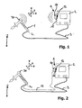
- Fig. 1 shows a schematic representation of a first embodiment of the hand-held tool 1 according to the invention with tool control 2.
- the tool control 2 is connected to the tool 1 via a connection 3.
- the connection 3 may comprise only an electrical connection as well as other other connections, for example a gas connection.
- the tool 1 is a welding torch which can be suitably controlled by a welding torch controller 2 with respect to various operating conditions. The operating conditions are set by predetermined control variables or control parameters in the tool control 2.
- the tool control 2 comprises a tool orientation unit 5 which comprises an orientation determination unit 10 and an output unit 11.
- the output unit 11 also has an interface 12 '(not shown here), which is connected to a corresponding mating interface, interface 12, the tool control 2 for communication.
- the tool orientation unit 5 comprises a sensor 30, which is firmly connected to the tool 1. According to the embodiment, the orientation of the tool 1 can be detected by means of the sensor 30 in a suitable manner as orientation data and transmitted to the orientation determination unit 10. Alternatively, detection of other suitable data by the sensor 30 is also provided, which, after being transmitted to the orientation determination unit 10, is suitable in orientation data can be converted.
- the orientation determination unit 10 can determine the orientation data or orientation-specific data which have been calculated from the orientation data by further processing, and transmit control parameters determined therefrom to the output unit 11, which in turn transmits the control parameters to the tool control 2.
- the tool control 2 controls the tool 1 in a suitable form on the basis of the control parameters of the tool orientation unit 5.
- suitable control variables or control parameters are determined from the orientation data or orientation-specific data, which correspond to a suitable operating state of the tool 1.
- the calculation of the control variables or control parameters can take place in the orientation determination unit 10 or the output unit 11.
- the orientation of the tool 10 relative to the direction of the gravity vector (g) is determined.
- the relative angle between the longitudinal extension L 1 of the tool handle of the tool 1 can be determined in comparison to the direction of the gravitational acceleration vector.
- the tool 1 is hereby freely movable in the entire space.
- suitable data is transmitted to the orientation determination unit 10. According to the execution of the transmission by wireless contact is wireless.
- the tool orientation unit 5 is provided as an external device for the tool control 2.
- the tool orientation unit 5 is connected to the tool control 2 via the interface 12 of the tool control 2.
- the tool orientation unit may already be integrated in the housing of the tool control 2.
- the communication between the tool orientation unit 5 and the tool control 2 can take place here via a suitable internal interface 12 of the tool control 2.
- the sensor 30 is detachably attached to the tool 1. The attachment can be done here in principle at any point of the tool 1.
- the sensor 30 is designed according to the embodiment as a three-dimensional acceleration sensor 30. Alternatively, three independent one-dimensional acceleration sensors are also possible, which can measure the different acceleration components in three directions. From the acceleration values, the orientation determination unit 10 can determine suitable orientation data that determines the relative angle between the direction of the Gravitational acceleration (e) and the longitudinal direction L 1 of the handle of the tool 1 determined.
- Fig. 2 a further embodiment of the tool according to the invention with tool control is shown, which is characterized by the in Fig. 1 illustrated embodiment only to the extent that the communication between the sensor 30 and the tool orientation unit 5 is not wireless but wired.
- the data determined by the sensor 30 are fed via a line 13 to the orientation determination unit 10.
- the line 13 can also be integrated into the connection 3 between the tool control 2 and the tool 1.
- Fig. 3 shows a schematic representation of the determination of the orientation of the tool 1 as orientation data in space.
- two positions of the tool 1 are characterized by two position vectors. The two positions differ by an angle ⁇ .
- the position vectors both different length and a different spatial direction (symbolized by the three-dimensional coordinate system with the axes x, y and z) assume.
- the orientation of the tool 1 can be determined as an angle change between the two position vectors, ie as an angle ⁇ .
- the position of the tool 1 is initialized, for example, by directing it to a certain position with respect to the direction of the gravitational acceleration vector, the further angular changes can be determined in the course of the working process by means of the orientation determination unit 10 as orientation data.
- the orientation data are then used to determine suitable control variables or control parameters for the control of the tool 1 in order to achieve an advantageous orientation-dependent control of the tool 1.
- Fig. 4 shows a detailed view of the tool orientation unit 5 according to the embodiment in Fig. 1 .
- an interface 12 of the tool control 2 is provided.
- the interface 12 is here with a further interface 12 'of the output unit 11 for communication connected.
- the data exchange is carried out according to the two-sided, ie data can be both transmitted from the output unit 11 and recorded.
- the interface 12 or 12 ' may also be provided only for one-way communication.
- the communication for output via an interface 12 'of the output unit 11 and the communication for recording by a further, not shown receiving unit of the tool orientation unit 5 can take place.
- Fig. 5 shows an embodiment of the inventive method for determining at least one control variable of a hand-held tool with tool control, in which initially the orientation of the tool 1 is determined.
- the determination of the orientation enables the calculation or determination of orientation data, which are compared in a second method step with corresponding comparison variables, ie comparison data.
- a comparison can be made explicitly by comparing individual data values, or implicitly by using the orientation data for further processing and, depending on the orientation, different comparison results can result.
- an analog control record the orientation data as a control voltage and output a further value corresponding to a characteristic. The output value thus corresponds to the comparison result.
- the comparison result or the orientation data allow the determination of orientation-specific data, which in the present case are transmitted to the tool control 2 via the interface 12 of the tool control 2 in the present case.
- the orientation data can also serve for the calculation of orientation-specific data before comparison with comparison variables.
- a method is in Fig. 6 schematically shown in a flow chart. After calculation or determination of the orientation-specific data from the orientation data, these are compared with corresponding comparison variables. The comparison can again take place in the tool orientation unit 5. After a successful comparison, the control parameters determined from the orientation-specific data can be transmitted in the same form or in a modified form to the tool control via the interface 12 of the tool control 2.
- Fig. 5 and Fig. 6 schematically illustrated embodiments of the invention Finally, at least one control variable of the tool for controlling the tool 1 is determined.
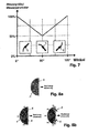
- Fig. 7 shows a schematic representation of the relative control or determination of at least one control variable or a control parameter in comparison to an absolute determination.
- a base value or reference value is specified according to the orientation of the tool 1 in space in an initial position. In the present case, the entire reference value at a zero-degree position is specified as 100%. Alternatively, this value can also be specified in the case of a 180-degree position of the tool 1.
- the angle refers to a relative deviation value between an initialization position vector representing the position of the tool 1 in space in comparison to the direction of the gravitational acceleration vector. The initialization vector is not shown here.
- a linear interpolation can be made between the values.
- the value of the control variable or the control parameter is thus changed in percent, the relative change in the extreme positions shown (zero degree angular position, 90 degree angular position and 180 degree angular position) are predetermined. Alternatively, any other kind of meaningful interpolation can take place between these extreme positions.
- control voltage or the control current of a welding torch can be purposefully reduced from a zero degree position (trough position, PA) to a 90 degree position (vertical position PF, PG) by determining the relative value or relative regulation.
- Fig. 8a shows a schematic representation of a continuous determination or control of at least one control variable of the tool 1 and a control parameter by means of a continuous analog control.
- the orientation of the tool 1 is continuously tracked from an initial 60 ° position to a 145 ° position.
- the change in orientation is transmitted as orientation data via the interface 12 to the tool control 2.
- a change of at least one control variable or a control parameter can be made.
- Fig. 8b illustrated discrete determination or discrete control, which provides predetermined orientation areas or orientation sectors.
- different control variables or control parameters are determined, which enable an advantageous embodiment of the working method.
- the one on the left in Fig. 8b illustrated embodiment distinguishes, for example, in three sectors P1, P2 and P3.
- the one on the right in Fig. 8b illustrated embodiment distinguishes in a total of five orientation areas or orientation sectors P1, P2, P3, P4, and P5. If the orientation of the tool 1 is changed within such an orientation region or orientation sector, no change in the control variable or the control parameter is made by the tool orientation unit 5. Accordingly, a continuous orientation determination of the tool 1 is not required, but can be replaced by a discrete regulation or determination.
Landscapes
- Engineering & Computer Science (AREA)
- Mechanical Engineering (AREA)
- Physics & Mathematics (AREA)
- Optics & Photonics (AREA)
- Portable Power Tools In General (AREA)
- Arc Welding Control (AREA)
- Arrangements For Transmission Of Measured Signals (AREA)
- Drilling And Boring (AREA)
- Numerical Control (AREA)
- Percussive Tools And Related Accessories (AREA)
Applications Claiming Priority (1)
| Application Number | Priority Date | Filing Date | Title |
|---|---|---|---|
| DE102011053799A DE102011053799A1 (de) | 2011-09-20 | 2011-09-20 | Verfahren zur Steuerung von wenigstens einer Steuergröße eines Werkzeugs sowie das Werkzeug |
Publications (2)
| Publication Number | Publication Date |
|---|---|
| EP2572833A2 true EP2572833A2 (fr) | 2013-03-27 |
| EP2572833A3 EP2572833A3 (fr) | 2018-04-04 |
Family
ID=46758654
Family Applications (1)
| Application Number | Title | Priority Date | Filing Date |
|---|---|---|---|
| EP12182894.1A Withdrawn EP2572833A3 (fr) | 2011-09-20 | 2012-09-04 | Procédé de commande d'au moins une grandeur de commande d'un outil ainsi que l'outil |
Country Status (6)
| Country | Link |
|---|---|
| US (1) | US20130068743A1 (fr) |
| EP (1) | EP2572833A3 (fr) |
| JP (1) | JP2013067000A (fr) |
| KR (1) | KR20130031226A (fr) |
| CN (1) | CN103009352A (fr) |
| DE (1) | DE102011053799A1 (fr) |
Families Citing this family (15)
| Publication number | Priority date | Publication date | Assignee | Title |
|---|---|---|---|---|
| DE102014209009A1 (de) * | 2014-01-27 | 2015-07-30 | Robert Bosch Gmbh | Werkzeugmaschinenvorrichtung |
| DE102014208980A1 (de) * | 2014-01-27 | 2015-07-30 | Robert Bosch Gmbh | Werkzeugmaschinenvorrichtung |
| DE102014209032A1 (de) | 2014-01-27 | 2015-07-30 | Robert Bosch Gmbh | Werkzeugmaschinenvorrichtung |
| US10335883B2 (en) * | 2014-06-05 | 2019-07-02 | Illinois Tool Works Inc. | Gravity-based weld travel speed sensing system and method |
| CN106537877A (zh) * | 2014-07-03 | 2017-03-22 | 阿特拉斯·科普柯工业技术公司 | 用于有利于在工作工具网络环境中通信的方法和系统 |
| DE102014223036A1 (de) * | 2014-11-12 | 2016-05-12 | Robert Bosch Gmbh | Werkzeug und verfahren zur behandlung eines werkstücks mit einem werkzeugelement eines werkzeugs |
| SE539516C2 (en) | 2016-03-31 | 2017-10-03 | Husqvarna Ab | Handheld chainsaw comprising at least one orientation sensor, a method of using the chainsaw and a mobile telephone to establish a connection to the chainsaw |
| US10437240B2 (en) * | 2016-09-13 | 2019-10-08 | Toyota Motor Engineering & Manufacturing North America, Inc. | Manufacturing evaluation system |
| DE102016224902A1 (de) * | 2016-12-14 | 2018-06-14 | Robert Bosch Gmbh | Tür-Rahmen-System für eine Schweisssteuerung und Verfahren zur Herstellung eines solchen Tür-Rahmen-Systems |
| JP2019018240A (ja) * | 2017-07-21 | 2019-02-07 | 日立Geニュークリア・エナジー株式会社 | 溶接制御システム、溶接用手袋および溶接訓練方法 |
| JP7045243B2 (ja) * | 2018-04-03 | 2022-03-31 | 株式会社ダイヘン | コンピュータプログラム、溶接情報算出装置、溶接トーチ、溶接電源、溶接システム |
| EP3892422A1 (fr) * | 2020-04-09 | 2021-10-13 | Hilti Aktiengesellschaft | Système de nivellement |
| EP4624088A3 (fr) * | 2021-03-16 | 2025-12-24 | Newfrey LLC | Pistolet de soudage et procédé de surveillance d'un processus de soudage |
| JP7687016B2 (ja) * | 2021-03-25 | 2025-06-03 | セイコーエプソン株式会社 | 立体物印刷方法 |
| CN116727962B (zh) * | 2023-05-04 | 2026-01-23 | 湖州东尼半导体科技有限公司 | 一种晶圆切割用金刚线锯接合修复设备 |
Citations (1)
| Publication number | Priority date | Publication date | Assignee | Title |
|---|---|---|---|---|
| EP1812200B1 (fr) | 2004-10-13 | 2009-05-13 | Erdogan Karakas | Dispositif pour la mise en oeuvre d'un procede de traitement de surface, d'assemblage ou de separation, en particulier d'un procede de soudage |
Family Cites Families (13)
| Publication number | Priority date | Publication date | Assignee | Title |
|---|---|---|---|---|
| JPH0866772A (ja) * | 1994-08-30 | 1996-03-12 | Mitsui Eng & Shipbuild Co Ltd | 曲り板継ぎの自動溶接法 |
| CA2265215C (fr) * | 1998-04-02 | 2004-06-22 | Lincoln Global, Inc. | Systeme de monitorage d'operation de soudage |
| JP2001162371A (ja) * | 1999-12-09 | 2001-06-19 | Daihen Corp | トーチ姿勢制御方法及び装置及びアーク溶接用ロボット |
| DE10117953A1 (de) * | 2001-04-10 | 2002-10-24 | Hilti Ag | Positionierhilfe für Handwerkzeuggerät |
| SI1559505T1 (sl) * | 2004-01-30 | 2007-02-28 | Tornos Sa | Postopek za izracun odstopanja pozicije nekega orodja med zazeleno in dejansko pozicijo orodja |
| DE102004046000B4 (de) * | 2004-09-17 | 2016-07-21 | C. & E. Fein Gmbh | Elektrowerkzeug mit einem Lage- und Orientierungssystem |
| DE102006034270A1 (de) * | 2006-07-18 | 2008-01-24 | C. & E. Fein Gmbh | Ortungssystem zur Ortung der Position eines Werkzeugs |
| US8915740B2 (en) * | 2008-08-21 | 2014-12-23 | Lincoln Global, Inc. | Virtual reality pipe welding simulator |
| JP2010058217A (ja) * | 2008-09-03 | 2010-03-18 | Toyota Auto Body Co Ltd | ネジの焼付き防止装置 |
| DE102008054455A1 (de) * | 2008-12-10 | 2010-06-17 | Robert Bosch Gmbh | Orientierungssensor, Orientierungsregler, Vorrichtung sowie System |
| US8274013B2 (en) * | 2009-03-09 | 2012-09-25 | Lincoln Global, Inc. | System for tracking and analyzing welding activity |
| DE102009046789A1 (de) * | 2009-11-17 | 2011-05-19 | Robert Bosch Gmbh | Handwerkzeugmaschinenvorrichtung |
| JP5252589B2 (ja) * | 2010-03-17 | 2013-07-31 | Necインフロンティア株式会社 | 傾き検出機能付き電動ドライバ及び電動ドライバによるネジ締め付け方法 |
-
2011
- 2011-09-20 DE DE102011053799A patent/DE102011053799A1/de not_active Ceased
-
2012
- 2012-09-04 EP EP12182894.1A patent/EP2572833A3/fr not_active Withdrawn
- 2012-09-18 US US13/622,011 patent/US20130068743A1/en not_active Abandoned
- 2012-09-19 JP JP2012205510A patent/JP2013067000A/ja active Pending
- 2012-09-20 KR KR1020120104491A patent/KR20130031226A/ko not_active Ceased
- 2012-09-20 CN CN2012103532735A patent/CN103009352A/zh active Pending
Patent Citations (1)
| Publication number | Priority date | Publication date | Assignee | Title |
|---|---|---|---|---|
| EP1812200B1 (fr) | 2004-10-13 | 2009-05-13 | Erdogan Karakas | Dispositif pour la mise en oeuvre d'un procede de traitement de surface, d'assemblage ou de separation, en particulier d'un procede de soudage |
Also Published As
| Publication number | Publication date |
|---|---|
| JP2013067000A (ja) | 2013-04-18 |
| KR20130031226A (ko) | 2013-03-28 |
| US20130068743A1 (en) | 2013-03-21 |
| EP2572833A3 (fr) | 2018-04-04 |
| DE102011053799A1 (de) | 2013-03-21 |
| CN103009352A (zh) | 2013-04-03 |
Similar Documents
| Publication | Publication Date | Title |
|---|---|---|
| EP2572833A2 (fr) | Procédé de commande d'au moins une grandeur de commande d'un outil ainsi que l'outil | |
| DE102014108956B4 (de) | Vorrichtung zum Entgraten mit visuellem Sensor und Kraftsensor | |
| AT398050B (de) | Schweissroboter | |
| AT509927B1 (de) | Verfahren zum programmieren oder vorgeben von bewegungen oder abläufen eines industrieroboters | |
| EP2581165A2 (fr) | Procédé de détermination d'un changement de position d'un outil ainsi que l'outil et la commande de l'outil | |
| DE69936073T2 (de) | Robotersteuerung | |
| DE19914245B4 (de) | Roboter-Steuervorrichtung | |
| DE202007011584U1 (de) | Schweißgerät | |
| DE102018215115A1 (de) | Programmiervorrichtung für einen Schweißroboter und Programmierverfahren für einen Schweißroboter | |
| DE102015114013B4 (de) | Verfahren und Vorrichtung zur Steuerung des Betriebs eines Roboters | |
| DE69506779T2 (de) | System zur automatischen Kontrolle der Schweissfugenform im Orbitalschweissverfahren für Rohre mit mittleren bis grossen Abmessungen | |
| DE3439096C2 (fr) | ||
| EP3530812A1 (fr) | Équipement pour travaux de forage et / ou de fondation | |
| DE102017120221B4 (de) | Steuereinheit | |
| EP2902859B1 (fr) | Dispositif de commande avec optimisateur intégré | |
| WO2018114306A1 (fr) | Système d'appareils pourvu d'un appareil outil ou d'un appareil de mesure | |
| EP3230015A1 (fr) | Procédé permettant de surveiller au moins un robot industriel, robot industriel et système muni de plusieurs robots industriels | |
| EP3706962B1 (fr) | Surveillance diversitaire anti-collision redondante | |
| EP2993012A1 (fr) | Procédé de commande d'un système de scie murale par sciage en long | |
| EP3676039B1 (fr) | Procédé et dispositif de fourniture d'un signal à distance référencé permettant la commande de positionnement d'un chalumeau soudeur | |
| EP4038308B1 (fr) | Applicateur de lubrifiant sur une presse métallique se présentant sous la forme d'une presse à étirer, d'une presse à tubes ou d'une presse à découper, et procédé de lubrification d'un mandrin sur une presse métallique se présentant sous la forme d'une presse à étirer, d'une presse à tubes ou d'une presse à découper | |
| DE202012013204U1 (de) | Manipulator | |
| DE102016115302B4 (de) | Robotersteuerungsvorrichtung zum steuern eines motorgetriebenen roboters | |
| DE4036297B4 (de) | Fortschalteinrichtung für den Werkzeughalter einer numerisch gesteuerten Drehbank | |
| EP3176658A1 (fr) | Unite de commande et procede de commande d'une machine-outil et son utilisation |
Legal Events
| Date | Code | Title | Description |
|---|---|---|---|
| PUAI | Public reference made under article 153(3) epc to a published international application that has entered the european phase |
Free format text: ORIGINAL CODE: 0009012 |
|
| AK | Designated contracting states |
Kind code of ref document: A2 Designated state(s): AL AT BE BG CH CY CZ DE DK EE ES FI FR GB GR HR HU IE IS IT LI LT LU LV MC MK MT NL NO PL PT RO RS SE SI SK SM TR |
|
| AX | Request for extension of the european patent |
Extension state: BA ME |
|
| RAP1 | Party data changed (applicant data changed or rights of an application transferred) |
Owner name: ILHUNG MANUFACTURING CO., LTD. |
|
| PUAL | Search report despatched |
Free format text: ORIGINAL CODE: 0009013 |
|
| AK | Designated contracting states |
Kind code of ref document: A3 Designated state(s): AL AT BE BG CH CY CZ DE DK EE ES FI FR GB GR HR HU IE IS IT LI LT LU LV MC MK MT NL NO PL PT RO RS SE SI SK SM TR |
|
| AX | Request for extension of the european patent |
Extension state: BA ME |
|
| RIC1 | Information provided on ipc code assigned before grant |
Ipc: B25F 5/00 20060101AFI20180226BHEP Ipc: B23K 37/02 20060101ALI20180226BHEP |
|
| STAA | Information on the status of an ep patent application or granted ep patent |
Free format text: STATUS: THE APPLICATION IS DEEMED TO BE WITHDRAWN |
|
| 18D | Application deemed to be withdrawn |
Effective date: 20181005 |