EP2572992A1 - Phare d'avion - Google Patents
Phare d'avion Download PDFInfo
- Publication number
- EP2572992A1 EP2572992A1 EP11182768A EP11182768A EP2572992A1 EP 2572992 A1 EP2572992 A1 EP 2572992A1 EP 11182768 A EP11182768 A EP 11182768A EP 11182768 A EP11182768 A EP 11182768A EP 2572992 A1 EP2572992 A1 EP 2572992A1
- Authority
- EP
- European Patent Office
- Prior art keywords
- heat sink
- light source
- sink element
- thermally
- light
- Prior art date
- Legal status (The legal status is an assumption and is not a legal conclusion. Google has not performed a legal analysis and makes no representation as to the accuracy of the status listed.)
- Granted
Links
- 239000003990 capacitor Substances 0.000 claims abstract description 34
- 230000008878 coupling Effects 0.000 claims abstract description 18
- 238000010168 coupling process Methods 0.000 claims abstract description 18
- 238000005859 coupling reaction Methods 0.000 claims abstract description 18
- 238000001816 cooling Methods 0.000 claims abstract description 7
- 230000015556 catabolic process Effects 0.000 description 2
- 238000006731 degradation reaction Methods 0.000 description 2
- 230000009977 dual effect Effects 0.000 description 2
- 239000012212 insulator Substances 0.000 description 2
- 238000013459 approach Methods 0.000 description 1
- 238000010276 construction Methods 0.000 description 1
- 238000013461 design Methods 0.000 description 1
- 230000000694 effects Effects 0.000 description 1
- 230000007613 environmental effect Effects 0.000 description 1
- 239000000463 material Substances 0.000 description 1
- 238000000034 method Methods 0.000 description 1
- 238000012986 modification Methods 0.000 description 1
- 230000004048 modification Effects 0.000 description 1
- 230000002441 reversible effect Effects 0.000 description 1
- 238000012546 transfer Methods 0.000 description 1
Images
Classifications
-
- B—PERFORMING OPERATIONS; TRANSPORTING
- B64—AIRCRAFT; AVIATION; COSMONAUTICS
- B64D—EQUIPMENT FOR FITTING IN OR TO AIRCRAFT; FLIGHT SUITS; PARACHUTES; ARRANGEMENT OR MOUNTING OF POWER PLANTS OR PROPULSION TRANSMISSIONS IN AIRCRAFT
- B64D47/00—Equipment not otherwise provided for
- B64D47/02—Arrangements or adaptations of signal or lighting devices
- B64D47/06—Arrangements or adaptations of signal or lighting devices for indicating aircraft presence
-
- F—MECHANICAL ENGINEERING; LIGHTING; HEATING; WEAPONS; BLASTING
- F21—LIGHTING
- F21S—NON-PORTABLE LIGHTING DEVICES; SYSTEMS THEREOF; VEHICLE LIGHTING DEVICES SPECIALLY ADAPTED FOR VEHICLE EXTERIORS
- F21S45/00—Arrangements within vehicle lighting devices specially adapted for vehicle exteriors, for purposes other than emission or distribution of light
- F21S45/40—Cooling of lighting devices
-
- F—MECHANICAL ENGINEERING; LIGHTING; HEATING; WEAPONS; BLASTING
- F21—LIGHTING
- F21S—NON-PORTABLE LIGHTING DEVICES; SYSTEMS THEREOF; VEHICLE LIGHTING DEVICES SPECIALLY ADAPTED FOR VEHICLE EXTERIORS
- F21S45/00—Arrangements within vehicle lighting devices specially adapted for vehicle exteriors, for purposes other than emission or distribution of light
- F21S45/40—Cooling of lighting devices
- F21S45/47—Passive cooling, e.g. using fins, thermal conductive elements or openings
- F21S45/48—Passive cooling, e.g. using fins, thermal conductive elements or openings with means for conducting heat from the inside to the outside of the lighting devices, e.g. with fins on the outer surface of the lighting device
-
- B—PERFORMING OPERATIONS; TRANSPORTING
- B64—AIRCRAFT; AVIATION; COSMONAUTICS
- B64D—EQUIPMENT FOR FITTING IN OR TO AIRCRAFT; FLIGHT SUITS; PARACHUTES; ARRANGEMENT OR MOUNTING OF POWER PLANTS OR PROPULSION TRANSMISSIONS IN AIRCRAFT
- B64D2203/00—Aircraft or airfield lights using LEDs
-
- F—MECHANICAL ENGINEERING; LIGHTING; HEATING; WEAPONS; BLASTING
- F21—LIGHTING
- F21S—NON-PORTABLE LIGHTING DEVICES; SYSTEMS THEREOF; VEHICLE LIGHTING DEVICES SPECIALLY ADAPTED FOR VEHICLE EXTERIORS
- F21S43/00—Signalling devices specially adapted for vehicle exteriors, e.g. brake lamps, direction indicator lights or reversing lights
- F21S43/10—Signalling devices specially adapted for vehicle exteriors, e.g. brake lamps, direction indicator lights or reversing lights characterised by the light source
- F21S43/13—Signalling devices specially adapted for vehicle exteriors, e.g. brake lamps, direction indicator lights or reversing lights characterised by the light source characterised by the type of light source
- F21S43/14—Light emitting diodes [LED]
-
- F—MECHANICAL ENGINEERING; LIGHTING; HEATING; WEAPONS; BLASTING
- F28—HEAT EXCHANGE IN GENERAL
- F28F—DETAILS OF HEAT-EXCHANGE AND HEAT-TRANSFER APPARATUS, OF GENERAL APPLICATION
- F28F13/00—Arrangements for modifying heat-transfer, e.g. increasing, decreasing
- F28F2013/005—Thermal joints
- F28F2013/008—Variable conductance materials; Thermal switches
Definitions
- the present invention relates to an aircraft light which can withstand temporary extreme thermal peak loads.
- an aircraft light comprises a housing and at least one light source located within the housing for emitting light.
- High intensity light sources can be rather sensitive to thermal loads so that heat generated upon operation of the light sources has to be dissipated.
- an aircraft light typically comprises a heat sink element for cooling the at least one light source. Part of the heat sink element forms at least a portion of the outer side of the housing which is exposed to the environment around the light in order to dissipate heat into this environment.
- This type of cooling concept is designed for cases in which the environment around the heat sink element can still receive thermal energy dissipated from the heat sink element. However, if the environment around the heat sink element for whatever reasons is overheated, the heat sink element cannot be used to transfer heat from the heat sink element to the environment. Depending on the time period for which these conditions last, this can result in a thermal distortion of the light sources.
- the present invention provides an aircraft light comprising
- the present invention solves the above-identified issue by thermally decoupling the at least one light source from the heat sink element during the time of an external extreme thermal energy input to the heat sink element.
- Thermal decoupling is performed with the aid of an actuator means which is thermally operated automatically in order to displace the at least one light source out of thermal coupling to the heat sink element and into thermal coupling to an internal auxiliary thermal capacitor for receiving thermal energy from the at least one light source.
- the auxiliary thermal capacitor is thermally decoupled from the heat sink element.
- the actuator means comprises a volume of a thermally expandable medium for displacing the at least one light source out of thermal coupling to the heat sink element and towards thermal coupling to the auxiliary thermal capacitor and vice versa, depending on the actual temperature of the heat sink element becoming higher or lower than a threshold value. Accordingly, during the period of time in which the at least one light source is thermally decoupled from the heat sink element, the self-induced thermal energy from the at least one light source is buffered in the auxiliary internal thermal capacitor until the housing and, in particular, the heat sink element forming at least a part of the outer side of the housing, is cooled off again.
- the thermally expandable medium no longer is expanded so that the at least one light source again becomes thermally decoupled from the auxiliary thermal capacitor and thermally coupled to the heat sink element. Also a discharge of the thermal capacitor to the housing (and, if necessary, the heat sink element) takes place again so that the auxiliary thermal capacitor is ready again for receiving thermal energy from the at least one light source in case that the heat sink element is exposed to external thermal energy inputs.
- the structure according to the invention can also be described as a smart thermal switch that couples and decouples the at least one temperature-sensitive light source in the manner of a dual clutch. If the exterior housing and exterior heat sink element portion get too hot, the energy path from the at least one light source is decoupled from the heat sink element and coupled to the inner thermal capacitor. This process is reversible and occurs once the exterior housing or heat sink element portion is cooling off again.
- the feature of selectively thermally coupling an electronic device e.g. circuitry or elements
- a heat sink is basically known from US-B-7 308 008 , US-A-2003/0076565 , US-A-2002/0114136 , EP-B-1 009 079 , EP-A-0 852 398 , DE-B-10 2006 037 747 , DE-A-195 37 633 and DE-U-20 2007 008 221 .
- thermally decoupling a thermal heat generating element from its associated heat sink element if the same itself is exposed to external thermal energy inputs, and thermally coupling the heat generating element to an auxiliary thermal capacitor thermally decoupled from the heat sink element.
- the thermally expandable medium can be a wax and/or can be encompassed by an elastic enclosure.
- the elastic enclosure can further be fixed to the at least one light source or an intermediate element to which the at least one light source is mounted.
- the light source is moved back and forth depending on the actual degree of expansion of the thermally expandable medium.
- the thermally expandable medium is in mechanical contact with the at least one light source or an intermediate element to which the at least one light source is mounted, wherein the actuator means comprises a resilient element for displacing the at least one light source for thermally decoupling it from the auxiliary thermal capacitor and for thermally coupling it with the heat sink element.
- the resilient element can be a spring element or the like elastically deformable element.
- the heat sink element comprises a contact side for thermally contacting the at least one light source or an intermediate element to which the at least one light source is mounted, wherein the contact side of the heat sink element comprises a recess accommodating the thermally expandable medium.
- a plurality of light sources are provided and mounted to a support element acting as an intermediate element for transmitting heat energy from the light sources to the heat sink element as long as in thermal contact with the same or from the light sources to the auxiliary thermal capacitor as long as in thermal contact therewith.
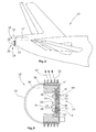
- Fig. 1 shows the tail portion of an aircraft 10 comprising an auxiliary power unit (APU) 12 having an outlet 14 located at the tail end 16 of the aircraft 10.
- APU auxiliary power unit
- the aircraft light 18 comprises a housing 20 formed at least in part by a portion 22 of a heat sink element 24 and a transparent cover 26.
- the aircraft light 18 is shown in more detail in the cross-sectional views of Figs. 1 and 2 .
- the portion 22 of the heat sink element 24 exposed to the environment around the aircraft light 18 is used to dissipate thermal energy from the heat sink element 24 to the environment.
- the heat sink element is exposed to external thermal inputs, unfortunately it can no longer serve as a heat dissipating element. This can happen e.g. if the exhaust gas of the APU 12 due to the actual wind conditions are directed (back) towards the heat sink element portion 22. Also in this condition, the light sources of the aircraft light 18 have to be effectively cooled to avoid degradation or in the extreme case distortion.
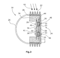
- the construction of the aircraft light 18 is shown in more detail in Figs. 2 and 3 .
- the heat sink element 24 comprises the portion 22 as well as another portion 28 as shown in Figs. 1 and 2 .
- This other plate-like portion 28 which also can have other geometric configurations, is provided with at least one recess 30 (in this embodiment there are two recesses 30) filled by a thermally expandable medium 32 which e.g. can be a wax.
- the thermally expandable medium 32 is included in an elastic envelope or enclosure 33.
- auxiliary thermal capacitor 34 Arranged within the housing 20 of the aircraft light 18 is an auxiliary thermal capacitor 34 which is thermally decoupled from the heat sink element 24. To this end, the auxiliary thermal capacitor 34 is located spaced apart from the heat sink element 24 so that a gap exists between both which can be filled by an insulator 36.
- the aircraft light 18 also comprises at least one light source 38, which in this embodiment can be formed by an LED.
- a plurality of light sources 38 i.e. a plurality of LEDs is provided.
- These light sources 38 are mounted to a common support 40 which in this embodiment is designed as a printed circuit board layer, The support 40 under normal thermal conditions is in contact with the heat sink element portion 28 so that the light sources 38 are thermally coupled to the heat sink element 24.
- Fig. 2 shows the operational situation of the aircraft light 18 under normal thermal conditions in which the heat sink element 24 is used to dissipate thermal energy from the light sources 38 via the heat sink element portion 22 to the environment (see heat flow arrows 42 in Fig, 2 ).
- the support 40 of the light sources 38 is in thermal (and mechanical) contact with the heat sink element 24 as shown in Fig. 2 .
- the support 40 can be regarded as an intermediate element 41 for thermally coupling the light sources 38 to the heat sink element 24 (and, if necessary, to the thermal capacitor 34).
- a resilient element 44 (spring or the like) is used so as to push the support 40 against the heat sink element portion 22.
- Fig. 3 shows the situation in which the heat sink element portion 22 is exposed to an external thermal energy input (see the heat flow arrows 46 in Fig. 3 ). Due to the external heat energy input, the heat sink element 24 is heated up to an extent beyond a threshold value beyond which the support 40 is displaced from the heat sink element 24 towards thermal contact with the auxiliary thermal capacitor 34. This is performed with the aid of the heat expandable medium 32 which under the influence of the increased temperatures expands and thereby pushes the support 40 against the spring biasing force of the resilient element 44 into thermal contact with the auxiliary thermal capacitor 34. Now the self-induced heat energy of the light sources 38 is received by the auxiliary thermal capacitor 34, resulting in a cooling effect to the light sources 38.
- the volume of the thermally expandable medium 32 (with or without the elastic envelope or enclosure 33) described above can be regarded as a thermal actuator means acting as a thermal switch for thermally coupling and decoupling the light sources 28 in a dual clutch way.
- the aircraft light typically can be provided with a unit connector which is not shown in detail in the above-mentioned Figures. Also, in these Figures the wiring is not shown in detail. Finally, in this embodiment the use of the aircraft light as a tail light is described. It is self-explanatory that also other applications of the aircraft light (both external and internal) are possible.
Landscapes
- Engineering & Computer Science (AREA)
- General Engineering & Computer Science (AREA)
- Aviation & Aerospace Engineering (AREA)
- Arrangement Of Elements, Cooling, Sealing, Or The Like Of Lighting Devices (AREA)
- Non-Portable Lighting Devices Or Systems Thereof (AREA)
Priority Applications (2)
| Application Number | Priority Date | Filing Date | Title |
|---|---|---|---|
| EP11182768.9A EP2572992B1 (fr) | 2011-09-26 | 2011-09-26 | Phare d'avion |
| US13/626,510 US8956021B2 (en) | 2011-09-26 | 2012-09-25 | Aircraft light |
Applications Claiming Priority (1)
| Application Number | Priority Date | Filing Date | Title |
|---|---|---|---|
| EP11182768.9A EP2572992B1 (fr) | 2011-09-26 | 2011-09-26 | Phare d'avion |
Publications (2)
| Publication Number | Publication Date |
|---|---|
| EP2572992A1 true EP2572992A1 (fr) | 2013-03-27 |
| EP2572992B1 EP2572992B1 (fr) | 2014-07-30 |
Family
ID=44785498
Family Applications (1)
| Application Number | Title | Priority Date | Filing Date |
|---|---|---|---|
| EP11182768.9A Not-in-force EP2572992B1 (fr) | 2011-09-26 | 2011-09-26 | Phare d'avion |
Country Status (2)
| Country | Link |
|---|---|
| US (1) | US8956021B2 (fr) |
| EP (1) | EP2572992B1 (fr) |
Cited By (4)
| Publication number | Priority date | Publication date | Assignee | Title |
|---|---|---|---|---|
| CN111630315A (zh) * | 2018-01-19 | 2020-09-04 | 株式会社小糸制作所 | 灯具单元、车辆用灯具以及灯具单元的制造方法 |
| WO2020182794A1 (fr) * | 2019-03-11 | 2020-09-17 | Continental Automotive Gmbh | Dispositif de diode thermique pour une uniteé de contrôle télématique de véhicule |
| US11052811B2 (en) | 2018-04-30 | 2021-07-06 | Toyota Motor Engineering & Manufacturing North America, Inc. | Mass transit for personal vehicles |
| US12504147B2 (en) | 2022-06-15 | 2025-12-23 | Goodrich Lighting Systems, Inc. | Lighting electronics cooling using high temp TEC with integrated heat sink |
Families Citing this family (12)
| Publication number | Priority date | Publication date | Assignee | Title |
|---|---|---|---|---|
| US8956023B1 (en) * | 2013-09-26 | 2015-02-17 | Goodrich Lighting Systems Gmbh | Combined wing scan and winglet illumination light unit and aircraft having winglet illumination |
| TWI560395B (en) * | 2014-06-10 | 2016-12-01 | World Corp Ag | Vehicular light system |
| FR3025781B1 (fr) * | 2014-09-12 | 2016-10-07 | Airbus | Aeronef comportant au moins une balise de secours |
| US10386131B2 (en) * | 2015-11-13 | 2019-08-20 | The Boeing Company | Self-regulating thermal insulation and related methods |
| AT518977B1 (de) * | 2016-11-17 | 2018-03-15 | Zkw Group Gmbh | Kühlkörper mit variablem thermischen Widerstand |
| TWI686691B (zh) * | 2018-08-16 | 2020-03-01 | 緯穎科技服務股份有限公司 | 電子裝置及被動元件 |
| EP4402417B1 (fr) * | 2021-09-16 | 2025-03-26 | Raytheon Company | Commutateur d'actionneur thermique conducteur à base de matériau à changement de phase (mcp) |
| EP4166457B1 (fr) * | 2021-10-14 | 2025-03-26 | Goodrich Corporation | Confinement de chaleur pour éclairage de queue d'aéronef |
| US12054285B2 (en) | 2021-10-14 | 2024-08-06 | Goodrich Corporation | Heat containment method for aircraft tail lighting |
| EP4292935A3 (fr) * | 2022-06-15 | 2024-02-28 | Goodrich Lighting Systems, Inc. | Refroidissement d'électronique d'éclairage à l'aide d'un tec à température élevée avec dissipateur thermique intégré |
| US12258948B2 (en) | 2022-09-16 | 2025-03-25 | Raytheon Company | Phase change material (PCM)-based conductive thermal actuator switches and associated stacked and arrayed systems |
| EP4682059A1 (fr) * | 2024-07-18 | 2026-01-21 | Goodrich Lighting Systems GmbH & Co. KG | Feu arrière d'aéronef, aéronef comprenant un feu arrière d'aéronef et procédé de fonctionnement d'un feu arrière d'aéronef |
Citations (11)
| Publication number | Priority date | Publication date | Assignee | Title |
|---|---|---|---|---|
| US4273183A (en) * | 1979-07-31 | 1981-06-16 | The United States Of America As Represented By The Secretary Of The Air Force | Mechanical heat transfer device |
| DE19537633A1 (de) | 1995-10-10 | 1997-04-17 | Daimler Benz Aerospace Ag | Wärmeleiter |
| EP0852398A1 (fr) | 1997-01-02 | 1998-07-08 | AT&T Corp. | Dispositif pour chauffer et refroidir un composant électronique |
| US20020114136A1 (en) | 2001-02-20 | 2002-08-22 | Marlon Cardenas | External attached heat sink fold out |
| US20030076565A1 (en) | 2001-10-02 | 2003-04-24 | Takatoshi Noda | Optical communication module |
| US6829145B1 (en) * | 2003-09-25 | 2004-12-07 | International Business Machines Corporation | Separable hybrid cold plate and heat sink device and method |
| EP1009079B1 (fr) | 1998-11-13 | 2007-08-01 | Oerlikon Space AG | Dispositif pour limiter la température d'un laser à diode pendant l'émission de lumière |
| DE202007008221U1 (de) | 2007-06-12 | 2007-10-11 | Knürr AG | Vorrichtung zur Übertragung von thermischer Energie |
| US7308008B2 (en) | 2002-11-08 | 2007-12-11 | Finisar Corporation | Magnetically controlled heat sink |
| DE102006037747A1 (de) | 2006-08-11 | 2008-03-13 | Nokia Siemens Networks Gmbh & Co.Kg | Anordnung zur Kühlung eines elektrischen Bauelements |
| EP2315285A1 (fr) * | 2009-10-22 | 2011-04-27 | Nxp B.V. | Appareil de régulation de la température d'une diode électroluminescente |
Family Cites Families (5)
| Publication number | Priority date | Publication date | Assignee | Title |
|---|---|---|---|---|
| WO2006014364A2 (fr) * | 2004-07-02 | 2006-02-09 | Discus Dental Impressions, Inc. | Lumiere de durcissement a pointe detachable |
| US20060018123A1 (en) * | 2004-07-02 | 2006-01-26 | Rose Eric P | Curing light having a reflector |
| JP5391767B2 (ja) * | 2008-05-30 | 2014-01-15 | 東芝ライテック株式会社 | 発光装置及び照明器具 |
| CN101776254B (zh) * | 2009-01-10 | 2012-11-21 | 富准精密工业(深圳)有限公司 | 发光二极管灯具及其光引擎 |
| US8692444B2 (en) * | 2010-03-16 | 2014-04-08 | Infinilux, Llc | Solid state low bay light with integrated and sealed thermal management |
-
2011
- 2011-09-26 EP EP11182768.9A patent/EP2572992B1/fr not_active Not-in-force
-
2012
- 2012-09-25 US US13/626,510 patent/US8956021B2/en not_active Expired - Fee Related
Patent Citations (11)
| Publication number | Priority date | Publication date | Assignee | Title |
|---|---|---|---|---|
| US4273183A (en) * | 1979-07-31 | 1981-06-16 | The United States Of America As Represented By The Secretary Of The Air Force | Mechanical heat transfer device |
| DE19537633A1 (de) | 1995-10-10 | 1997-04-17 | Daimler Benz Aerospace Ag | Wärmeleiter |
| EP0852398A1 (fr) | 1997-01-02 | 1998-07-08 | AT&T Corp. | Dispositif pour chauffer et refroidir un composant électronique |
| EP1009079B1 (fr) | 1998-11-13 | 2007-08-01 | Oerlikon Space AG | Dispositif pour limiter la température d'un laser à diode pendant l'émission de lumière |
| US20020114136A1 (en) | 2001-02-20 | 2002-08-22 | Marlon Cardenas | External attached heat sink fold out |
| US20030076565A1 (en) | 2001-10-02 | 2003-04-24 | Takatoshi Noda | Optical communication module |
| US7308008B2 (en) | 2002-11-08 | 2007-12-11 | Finisar Corporation | Magnetically controlled heat sink |
| US6829145B1 (en) * | 2003-09-25 | 2004-12-07 | International Business Machines Corporation | Separable hybrid cold plate and heat sink device and method |
| DE102006037747A1 (de) | 2006-08-11 | 2008-03-13 | Nokia Siemens Networks Gmbh & Co.Kg | Anordnung zur Kühlung eines elektrischen Bauelements |
| DE202007008221U1 (de) | 2007-06-12 | 2007-10-11 | Knürr AG | Vorrichtung zur Übertragung von thermischer Energie |
| EP2315285A1 (fr) * | 2009-10-22 | 2011-04-27 | Nxp B.V. | Appareil de régulation de la température d'une diode électroluminescente |
Cited By (6)
| Publication number | Priority date | Publication date | Assignee | Title |
|---|---|---|---|---|
| CN111630315A (zh) * | 2018-01-19 | 2020-09-04 | 株式会社小糸制作所 | 灯具单元、车辆用灯具以及灯具单元的制造方法 |
| US11052811B2 (en) | 2018-04-30 | 2021-07-06 | Toyota Motor Engineering & Manufacturing North America, Inc. | Mass transit for personal vehicles |
| WO2020182794A1 (fr) * | 2019-03-11 | 2020-09-17 | Continental Automotive Gmbh | Dispositif de diode thermique pour une uniteé de contrôle télématique de véhicule |
| FR3093890A1 (fr) * | 2019-03-11 | 2020-09-18 | Continental Automotive Gmbh | Dispositif de diode thermique pour une unité électronique |
| US12010821B2 (en) | 2019-03-11 | 2024-06-11 | Continental Automotive Gmbh | Thermal diode device for a telematic control unit of a vehicle |
| US12504147B2 (en) | 2022-06-15 | 2025-12-23 | Goodrich Lighting Systems, Inc. | Lighting electronics cooling using high temp TEC with integrated heat sink |
Also Published As
| Publication number | Publication date |
|---|---|
| US20130077331A1 (en) | 2013-03-28 |
| EP2572992B1 (fr) | 2014-07-30 |
| US8956021B2 (en) | 2015-02-17 |
Similar Documents
| Publication | Publication Date | Title |
|---|---|---|
| EP2572992B1 (fr) | Phare d'avion | |
| US7272002B2 (en) | Auxiliary cooling methods and systems for electrical device housings | |
| CN105101747A (zh) | 用于电子系统的热夹具设备 | |
| EP3509099B1 (fr) | Dissipateur thermique | |
| CN205232671U (zh) | 一种导热弹片及安装有该导热弹片的发热体 | |
| WO2023231369A1 (fr) | Structure de dissipation de chaleur, dispositif monté sur un véhicule et équipement terminal | |
| EP2717463B1 (fr) | Freinage de moteur électrique utilisant un refroidissement thermoélectrique | |
| JP2009111310A (ja) | 電子機器の放熱構造 | |
| JP2012159509A (ja) | 赤外線センサ | |
| WO2009138833A3 (fr) | Couplage destiné à provoquer des chutes de température importantes entre des parties reliées sur un aéronef | |
| KR20140108145A (ko) | 냉각 장치용 시스템 | |
| CN103797900B (zh) | 用于冷却自动化系统或控制系统的部件的组件 | |
| EP2853682A1 (fr) | Système d'enceinte sous-marine destiné à l'élimination de la chaleur générée | |
| CN102986318B (zh) | 热控制组件 | |
| CN113009992A (zh) | 用于电路板的多区域冷却体 | |
| CN107003091A (zh) | 传递热的补偿元件以及能电运行的具有这种补偿元件的车辆 | |
| KR20190116381A (ko) | 다층 세라믹을 위한 집적 온도 제어 및 방법 | |
| CN220253551U (zh) | 一种新型的半导体制冷电连接器 | |
| CN105051629B (zh) | 可编程逻辑控制器 | |
| US12010821B2 (en) | Thermal diode device for a telematic control unit of a vehicle | |
| CN201255863Y (zh) | 一种服务器散热结构和服务器 | |
| CN106285921B (zh) | 用于涡轮增压器致动器的冷却装置 | |
| CN205755222U (zh) | 一种高功耗电路板的散热装置 | |
| KR20160135066A (ko) | 케이스를 이용한 방열구조를 갖는 네트워크 장치 | |
| US10568197B1 (en) | Combined heat sink and photon harvestor |
Legal Events
| Date | Code | Title | Description |
|---|---|---|---|
| PUAI | Public reference made under article 153(3) epc to a published international application that has entered the european phase |
Free format text: ORIGINAL CODE: 0009012 |
|
| AK | Designated contracting states |
Kind code of ref document: A1 Designated state(s): AL AT BE BG CH CY CZ DE DK EE ES FI FR GB GR HR HU IE IS IT LI LT LU LV MC MK MT NL NO PL PT RO RS SE SI SK SM TR |
|
| AX | Request for extension of the european patent |
Extension state: BA ME |
|
| 17P | Request for examination filed |
Effective date: 20130923 |
|
| RBV | Designated contracting states (corrected) |
Designated state(s): AL AT BE BG CH CY CZ DE DK EE ES FI FR GB GR HR HU IE IS IT LI LT LU LV MC MK MT NL NO PL PT RO RS SE SI SK SM TR |
|
| RIC1 | Information provided on ipc code assigned before grant |
Ipc: B64D 47/06 20060101AFI20131211BHEP Ipc: F21V 29/00 20060101ALI20131211BHEP Ipc: F21Y 101/02 20060101ALN20131211BHEP |
|
| RIC1 | Information provided on ipc code assigned before grant |
Ipc: F21V 29/00 20060101ALI20131213BHEP Ipc: B64D 47/06 20060101AFI20131213BHEP Ipc: F21Y 101/02 20060101ALN20131213BHEP |
|
| GRAP | Despatch of communication of intention to grant a patent |
Free format text: ORIGINAL CODE: EPIDOSNIGR1 |
|
| INTG | Intention to grant announced |
Effective date: 20140225 |
|
| GRAS | Grant fee paid |
Free format text: ORIGINAL CODE: EPIDOSNIGR3 |
|
| GRAA | (expected) grant |
Free format text: ORIGINAL CODE: 0009210 |
|
| AK | Designated contracting states |
Kind code of ref document: B1 Designated state(s): AL AT BE BG CH CY CZ DE DK EE ES FI FR GB GR HR HU IE IS IT LI LT LU LV MC MK MT NL NO PL PT RO RS SE SI SK SM TR |
|
| REG | Reference to a national code |
Ref country code: GB Ref legal event code: FG4D |
|
| REG | Reference to a national code |
Ref country code: CH Ref legal event code: EP |
|
| REG | Reference to a national code |
Ref country code: AT Ref legal event code: REF Ref document number: 679828 Country of ref document: AT Kind code of ref document: T Effective date: 20140815 |
|
| REG | Reference to a national code |
Ref country code: IE Ref legal event code: FG4D |
|
| REG | Reference to a national code |
Ref country code: DE Ref legal event code: R096 Ref document number: 602011008682 Country of ref document: DE Effective date: 20140911 |
|
| REG | Reference to a national code |
Ref country code: AT Ref legal event code: MK05 Ref document number: 679828 Country of ref document: AT Kind code of ref document: T Effective date: 20140730 |
|
| REG | Reference to a national code |
Ref country code: NL Ref legal event code: VDEP Effective date: 20140730 |
|
| REG | Reference to a national code |
Ref country code: LT Ref legal event code: MG4D |
|
| PG25 | Lapsed in a contracting state [announced via postgrant information from national office to epo] |
Ref country code: GR Free format text: LAPSE BECAUSE OF FAILURE TO SUBMIT A TRANSLATION OF THE DESCRIPTION OR TO PAY THE FEE WITHIN THE PRESCRIBED TIME-LIMIT Effective date: 20141031 Ref country code: SE Free format text: LAPSE BECAUSE OF FAILURE TO SUBMIT A TRANSLATION OF THE DESCRIPTION OR TO PAY THE FEE WITHIN THE PRESCRIBED TIME-LIMIT Effective date: 20140730 Ref country code: NO Free format text: LAPSE BECAUSE OF FAILURE TO SUBMIT A TRANSLATION OF THE DESCRIPTION OR TO PAY THE FEE WITHIN THE PRESCRIBED TIME-LIMIT Effective date: 20141030 Ref country code: BG Free format text: LAPSE BECAUSE OF FAILURE TO SUBMIT A TRANSLATION OF THE DESCRIPTION OR TO PAY THE FEE WITHIN THE PRESCRIBED TIME-LIMIT Effective date: 20141030 Ref country code: FI Free format text: LAPSE BECAUSE OF FAILURE TO SUBMIT A TRANSLATION OF THE DESCRIPTION OR TO PAY THE FEE WITHIN THE PRESCRIBED TIME-LIMIT Effective date: 20140730 Ref country code: PT Free format text: LAPSE BECAUSE OF FAILURE TO SUBMIT A TRANSLATION OF THE DESCRIPTION OR TO PAY THE FEE WITHIN THE PRESCRIBED TIME-LIMIT Effective date: 20141202 Ref country code: ES Free format text: LAPSE BECAUSE OF FAILURE TO SUBMIT A TRANSLATION OF THE DESCRIPTION OR TO PAY THE FEE WITHIN THE PRESCRIBED TIME-LIMIT Effective date: 20140730 Ref country code: LT Free format text: LAPSE BECAUSE OF FAILURE TO SUBMIT A TRANSLATION OF THE DESCRIPTION OR TO PAY THE FEE WITHIN THE PRESCRIBED TIME-LIMIT Effective date: 20140730 |
|
| PG25 | Lapsed in a contracting state [announced via postgrant information from national office to epo] |
Ref country code: CY Free format text: LAPSE BECAUSE OF FAILURE TO SUBMIT A TRANSLATION OF THE DESCRIPTION OR TO PAY THE FEE WITHIN THE PRESCRIBED TIME-LIMIT Effective date: 20140730 Ref country code: LV Free format text: LAPSE BECAUSE OF FAILURE TO SUBMIT A TRANSLATION OF THE DESCRIPTION OR TO PAY THE FEE WITHIN THE PRESCRIBED TIME-LIMIT Effective date: 20140730 Ref country code: HR Free format text: LAPSE BECAUSE OF FAILURE TO SUBMIT A TRANSLATION OF THE DESCRIPTION OR TO PAY THE FEE WITHIN THE PRESCRIBED TIME-LIMIT Effective date: 20140730 Ref country code: AT Free format text: LAPSE BECAUSE OF FAILURE TO SUBMIT A TRANSLATION OF THE DESCRIPTION OR TO PAY THE FEE WITHIN THE PRESCRIBED TIME-LIMIT Effective date: 20140730 Ref country code: IS Free format text: LAPSE BECAUSE OF FAILURE TO SUBMIT A TRANSLATION OF THE DESCRIPTION OR TO PAY THE FEE WITHIN THE PRESCRIBED TIME-LIMIT Effective date: 20141130 Ref country code: RS Free format text: LAPSE BECAUSE OF FAILURE TO SUBMIT A TRANSLATION OF THE DESCRIPTION OR TO PAY THE FEE WITHIN THE PRESCRIBED TIME-LIMIT Effective date: 20140730 Ref country code: PL Free format text: LAPSE BECAUSE OF FAILURE TO SUBMIT A TRANSLATION OF THE DESCRIPTION OR TO PAY THE FEE WITHIN THE PRESCRIBED TIME-LIMIT Effective date: 20140730 Ref country code: NL Free format text: LAPSE BECAUSE OF FAILURE TO SUBMIT A TRANSLATION OF THE DESCRIPTION OR TO PAY THE FEE WITHIN THE PRESCRIBED TIME-LIMIT Effective date: 20140730 |
|
| PG25 | Lapsed in a contracting state [announced via postgrant information from national office to epo] |
Ref country code: SK Free format text: LAPSE BECAUSE OF FAILURE TO SUBMIT A TRANSLATION OF THE DESCRIPTION OR TO PAY THE FEE WITHIN THE PRESCRIBED TIME-LIMIT Effective date: 20140730 Ref country code: CZ Free format text: LAPSE BECAUSE OF FAILURE TO SUBMIT A TRANSLATION OF THE DESCRIPTION OR TO PAY THE FEE WITHIN THE PRESCRIBED TIME-LIMIT Effective date: 20140730 Ref country code: LU Free format text: LAPSE BECAUSE OF FAILURE TO SUBMIT A TRANSLATION OF THE DESCRIPTION OR TO PAY THE FEE WITHIN THE PRESCRIBED TIME-LIMIT Effective date: 20140926 Ref country code: IT Free format text: LAPSE BECAUSE OF FAILURE TO SUBMIT A TRANSLATION OF THE DESCRIPTION OR TO PAY THE FEE WITHIN THE PRESCRIBED TIME-LIMIT Effective date: 20140730 Ref country code: MC Free format text: LAPSE BECAUSE OF FAILURE TO SUBMIT A TRANSLATION OF THE DESCRIPTION OR TO PAY THE FEE WITHIN THE PRESCRIBED TIME-LIMIT Effective date: 20140730 Ref country code: EE Free format text: LAPSE BECAUSE OF FAILURE TO SUBMIT A TRANSLATION OF THE DESCRIPTION OR TO PAY THE FEE WITHIN THE PRESCRIBED TIME-LIMIT Effective date: 20140730 Ref country code: RO Free format text: LAPSE BECAUSE OF FAILURE TO SUBMIT A TRANSLATION OF THE DESCRIPTION OR TO PAY THE FEE WITHIN THE PRESCRIBED TIME-LIMIT Effective date: 20140730 Ref country code: DK Free format text: LAPSE BECAUSE OF FAILURE TO SUBMIT A TRANSLATION OF THE DESCRIPTION OR TO PAY THE FEE WITHIN THE PRESCRIBED TIME-LIMIT Effective date: 20140730 |
|
| REG | Reference to a national code |
Ref country code: CH Ref legal event code: PL |
|
| REG | Reference to a national code |
Ref country code: DE Ref legal event code: R097 Ref document number: 602011008682 Country of ref document: DE |
|
| PLBE | No opposition filed within time limit |
Free format text: ORIGINAL CODE: 0009261 |
|
| STAA | Information on the status of an ep patent application or granted ep patent |
Free format text: STATUS: NO OPPOSITION FILED WITHIN TIME LIMIT |
|
| REG | Reference to a national code |
Ref country code: IE Ref legal event code: MM4A |
|
| PG25 | Lapsed in a contracting state [announced via postgrant information from national office to epo] |
Ref country code: BE Free format text: LAPSE BECAUSE OF NON-PAYMENT OF DUE FEES Effective date: 20140930 |
|
| 26N | No opposition filed |
Effective date: 20150504 |
|
| PG25 | Lapsed in a contracting state [announced via postgrant information from national office to epo] |
Ref country code: CH Free format text: LAPSE BECAUSE OF NON-PAYMENT OF DUE FEES Effective date: 20140930 Ref country code: LI Free format text: LAPSE BECAUSE OF NON-PAYMENT OF DUE FEES Effective date: 20140930 |
|
| REG | Reference to a national code |
Ref country code: FR Ref legal event code: PLFP Year of fee payment: 5 |
|
| PG25 | Lapsed in a contracting state [announced via postgrant information from national office to epo] |
Ref country code: IE Free format text: LAPSE BECAUSE OF NON-PAYMENT OF DUE FEES Effective date: 20140926 |
|
| PGFP | Annual fee paid to national office [announced via postgrant information from national office to epo] |
Ref country code: DE Payment date: 20150820 Year of fee payment: 5 |
|
| PG25 | Lapsed in a contracting state [announced via postgrant information from national office to epo] |
Ref country code: SI Free format text: LAPSE BECAUSE OF FAILURE TO SUBMIT A TRANSLATION OF THE DESCRIPTION OR TO PAY THE FEE WITHIN THE PRESCRIBED TIME-LIMIT Effective date: 20140730 |
|
| PGFP | Annual fee paid to national office [announced via postgrant information from national office to epo] |
Ref country code: FR Payment date: 20150824 Year of fee payment: 5 |
|
| PG25 | Lapsed in a contracting state [announced via postgrant information from national office to epo] |
Ref country code: SM Free format text: LAPSE BECAUSE OF FAILURE TO SUBMIT A TRANSLATION OF THE DESCRIPTION OR TO PAY THE FEE WITHIN THE PRESCRIBED TIME-LIMIT Effective date: 20140730 |
|
| GBPC | Gb: european patent ceased through non-payment of renewal fee |
Effective date: 20150926 |
|
| PG25 | Lapsed in a contracting state [announced via postgrant information from national office to epo] |
Ref country code: MT Free format text: LAPSE BECAUSE OF FAILURE TO SUBMIT A TRANSLATION OF THE DESCRIPTION OR TO PAY THE FEE WITHIN THE PRESCRIBED TIME-LIMIT Effective date: 20140730 |
|
| PG25 | Lapsed in a contracting state [announced via postgrant information from national office to epo] |
Ref country code: TR Free format text: LAPSE BECAUSE OF FAILURE TO SUBMIT A TRANSLATION OF THE DESCRIPTION OR TO PAY THE FEE WITHIN THE PRESCRIBED TIME-LIMIT Effective date: 20140730 Ref country code: GB Free format text: LAPSE BECAUSE OF NON-PAYMENT OF DUE FEES Effective date: 20150926 Ref country code: BE Free format text: LAPSE BECAUSE OF FAILURE TO SUBMIT A TRANSLATION OF THE DESCRIPTION OR TO PAY THE FEE WITHIN THE PRESCRIBED TIME-LIMIT Effective date: 20140730 Ref country code: HU Free format text: LAPSE BECAUSE OF FAILURE TO SUBMIT A TRANSLATION OF THE DESCRIPTION OR TO PAY THE FEE WITHIN THE PRESCRIBED TIME-LIMIT; INVALID AB INITIO Effective date: 20110926 |
|
| REG | Reference to a national code |
Ref country code: DE Ref legal event code: R119 Ref document number: 602011008682 Country of ref document: DE |
|
| REG | Reference to a national code |
Ref country code: FR Ref legal event code: ST Effective date: 20170531 |
|
| PG25 | Lapsed in a contracting state [announced via postgrant information from national office to epo] |
Ref country code: DE Free format text: LAPSE BECAUSE OF NON-PAYMENT OF DUE FEES Effective date: 20170401 Ref country code: FR Free format text: LAPSE BECAUSE OF NON-PAYMENT OF DUE FEES Effective date: 20160930 |
|
| PG25 | Lapsed in a contracting state [announced via postgrant information from national office to epo] |
Ref country code: MK Free format text: LAPSE BECAUSE OF FAILURE TO SUBMIT A TRANSLATION OF THE DESCRIPTION OR TO PAY THE FEE WITHIN THE PRESCRIBED TIME-LIMIT Effective date: 20140730 |
|
| PG25 | Lapsed in a contracting state [announced via postgrant information from national office to epo] |
Ref country code: AL Free format text: LAPSE BECAUSE OF FAILURE TO SUBMIT A TRANSLATION OF THE DESCRIPTION OR TO PAY THE FEE WITHIN THE PRESCRIBED TIME-LIMIT Effective date: 20140730 |
|
| RIC2 | Information provided on ipc code assigned after grant |
Ipc: F21Y 101/02 20000101ALN20131213BHEP Ipc: F21V 29/00 20150101ALI20131213BHEP Ipc: B64D 47/06 20060101AFI20131213BHEP |