EP2573005A1 - Distributeur compte-gouttes - Google Patents
Distributeur compte-gouttes Download PDFInfo
- Publication number
- EP2573005A1 EP2573005A1 EP12183511A EP12183511A EP2573005A1 EP 2573005 A1 EP2573005 A1 EP 2573005A1 EP 12183511 A EP12183511 A EP 12183511A EP 12183511 A EP12183511 A EP 12183511A EP 2573005 A1 EP2573005 A1 EP 2573005A1
- Authority
- EP
- European Patent Office
- Prior art keywords
- droplet
- drop
- housing
- dispenser
- discharge opening
- Prior art date
- Legal status (The legal status is an assumption and is not a legal conclusion. Google has not performed a legal analysis and makes no representation as to the accuracy of the status listed.)
- Granted
Links
Images

Classifications
-
- B—PERFORMING OPERATIONS; TRANSPORTING
- B65—CONVEYING; PACKING; STORING; HANDLING THIN OR FILAMENTARY MATERIAL
- B65D—CONTAINERS FOR STORAGE OR TRANSPORT OF ARTICLES OR MATERIALS, e.g. BAGS, BARRELS, BOTTLES, BOXES, CANS, CARTONS, CRATES, DRUMS, JARS, TANKS, HOPPERS, FORWARDING CONTAINERS; ACCESSORIES, CLOSURES, OR FITTINGS THEREFOR; PACKAGING ELEMENTS; PACKAGES
- B65D47/00—Closures with filling and discharging, or with discharging, devices
- B65D47/04—Closures with discharging devices other than pumps
- B65D47/06—Closures with discharging devices other than pumps with pouring spouts or tubes; with discharge nozzles or passages
- B65D47/18—Closures with discharging devices other than pumps with pouring spouts or tubes; with discharge nozzles or passages for discharging drops; Droppers
-
- A—HUMAN NECESSITIES
- A61—MEDICAL OR VETERINARY SCIENCE; HYGIENE
- A61F—FILTERS IMPLANTABLE INTO BLOOD VESSELS; PROSTHESES; DEVICES PROVIDING PATENCY TO, OR PREVENTING COLLAPSING OF, TUBULAR STRUCTURES OF THE BODY, e.g. STENTS; ORTHOPAEDIC, NURSING OR CONTRACEPTIVE DEVICES; FOMENTATION; TREATMENT OR PROTECTION OF EYES OR EARS; BANDAGES, DRESSINGS OR ABSORBENT PADS; FIRST-AID KITS
- A61F9/00—Methods or devices for treatment of the eyes; Devices for putting in contact-lenses; Devices to correct squinting; Apparatus to guide the blind; Protective devices for the eyes, carried on the body or in the hand
- A61F9/0008—Introducing ophthalmic products into the ocular cavity or retaining products therein
-
- B—PERFORMING OPERATIONS; TRANSPORTING
- B01—PHYSICAL OR CHEMICAL PROCESSES OR APPARATUS IN GENERAL
- B01L—CHEMICAL OR PHYSICAL LABORATORY APPARATUS FOR GENERAL USE
- B01L3/00—Containers or dishes for laboratory use, e.g. laboratory glassware; Droppers
-
- B—PERFORMING OPERATIONS; TRANSPORTING
- B01—PHYSICAL OR CHEMICAL PROCESSES OR APPARATUS IN GENERAL
- B01L—CHEMICAL OR PHYSICAL LABORATORY APPARATUS FOR GENERAL USE
- B01L3/00—Containers or dishes for laboratory use, e.g. laboratory glassware; Droppers
- B01L3/02—Burettes; Pipettes
- B01L3/0241—Drop counters; Drop formers
- B01L3/0272—Dropper bottles
-
- B—PERFORMING OPERATIONS; TRANSPORTING
- B65—CONVEYING; PACKING; STORING; HANDLING THIN OR FILAMENTARY MATERIAL
- B65D—CONTAINERS FOR STORAGE OR TRANSPORT OF ARTICLES OR MATERIALS, e.g. BAGS, BARRELS, BOTTLES, BOXES, CANS, CARTONS, CRATES, DRUMS, JARS, TANKS, HOPPERS, FORWARDING CONTAINERS; ACCESSORIES, CLOSURES, OR FITTINGS THEREFOR; PACKAGING ELEMENTS; PACKAGES
- B65D47/00—Closures with filling and discharging, or with discharging, devices
- B65D47/04—Closures with discharging devices other than pumps
- B65D47/20—Closures with discharging devices other than pumps comprising hand-operated members for controlling discharge
- B65D47/2018—Closures with discharging devices other than pumps comprising hand-operated members for controlling discharge comprising a valve or like element which is opened or closed by deformation of the container or closure
- B65D47/2056—Closures with discharging devices other than pumps comprising hand-operated members for controlling discharge comprising a valve or like element which is opened or closed by deformation of the container or closure lift valve type
- B65D47/2062—Closures with discharging devices other than pumps comprising hand-operated members for controlling discharge comprising a valve or like element which is opened or closed by deformation of the container or closure lift valve type in which the deformation raises or lowers the valve stem
- B65D47/2068—Closures with discharging devices other than pumps comprising hand-operated members for controlling discharge comprising a valve or like element which is opened or closed by deformation of the container or closure lift valve type in which the deformation raises or lowers the valve stem in which the stem is lowered by the pressure of the contents and thereby opening the valve
-
- B—PERFORMING OPERATIONS; TRANSPORTING
- B01—PHYSICAL OR CHEMICAL PROCESSES OR APPARATUS IN GENERAL
- B01L—CHEMICAL OR PHYSICAL LABORATORY APPARATUS FOR GENERAL USE
- B01L2300/00—Additional constructional details
- B01L2300/16—Surface properties and coatings
- B01L2300/161—Control and use of surface tension forces, e.g. hydrophobic, hydrophilic
Definitions
- the invention relates to a drop dispenser for dispensing a pharmaceutical liquid in drop form.
- a drop dispenser for dispensing a pharmaceutical liquid in drop form.
- a generic drop dispenser on a housing and a liquid reservoir and a discharge opening for discharging the liquid, which penetrates a wall of the housing and is associated with an outlet valve.
- Drop dispensers are well known for administering various medicaments known in the art. They have a liquid reservoir, which may be formed, for example, as a squeeze bottle and causes by pressing together with simultaneously pointing downward discharge opening a promotion of the liquid through the discharge opening. On the outside of the discharge opening forms in such a drop dispenser intended a drop that separates from the dispenser when it has a sufficient size, which leads to a constriction of the major part of the discharged amount of liquid in the form of a main drop. In the environment of Discharge usually remains a technically hardly avoidable residual drops.
- the object of the invention is to develop a generic drop dispenser to the effect that this allows a particularly rapid evaporation of the residual drop. Another object is to provide a drop dispenser in which the liquid volume of each drop is substantially constant.
- this object is fulfilled according to a first aspect of the invention in that the discharge opening is surrounded by a drop formation surface on the outside of the housing, wherein these Drop formation surface at least in an outer region - with respect to an orientation of the drop dispenser with vertically downwardly facing discharge opening - has a downwardly and tapering to the discharge opening shape and is also formed hydrophilic.
- the invention thus relates in particular to the shaping and design of the droplet formation surface, which is the surface to which the droplet to be dispensed adheres as intended, before it at least for the most part separates from the dispenser.
- the downwardly tapering shape of the exterior of this droplet forming surface is to be understood in particular as a conical or frusto-conical shape, whereby e.g. spherical forms are possible.
- the lateral surface of which is arranged on the outside of the discharge opening and formed hydrophilic.
- hydrophilic design of said surface is meant that under reference conditions of water at 20 ° C, a measure of the hydrophilicity reproducing contact angle between said water and the surface is 20 ° or less, in particular preferably 10 ° or less.
- the combination of the tapered and hydrophilic formed droplet forming surface surrounding the discharge opening has been found to be particularly advantageous in view of the evaporation time of the residual droplet.
- a larger area is provided on which this residual drop is distributed, compared with a planar design of a droplet-forming surface and assuming an equal outer diameter of the residual droplet remaining on the dispenser.
- the residual drop usually has a smaller volume.
- this advantage of the reduced evaporation time is also given if not only a limited drop formation surface, but instead the entire donor is hydrophilic on its outer side.
- the drop formation surface is localized. This may be achieved, for example, by surrounding the droplet formation surface with an environmental surface that has a lower hydrophilicity than the droplet formation surface.
- the hydrophilicity in the peripheral surface surrounding the droplet-forming surface is such that it leads to a contact angle greater than 20 °, preferably greater than 45 °, under the abovementioned boundary conditions.
- the droplet formation surface on the outside by an edge that has a maximum radius of curvature of 0.2 mm.
- a boundary edge also enhances the tendency of the main drop to detach from the residual droplet even before liquid passes over said boundary edge Leaves the hydrophilic droplet forming surface.
- the boundary edge is realized together with the surrounding area of lesser hydrophilicity. Conceivable, however, is quite a design in which the surface outside the boundary edge is also hydrophilic and thus the boundary edge alone is responsible for the fact that in the formation of drops, the liquid does not exceed the limits of the drop formation surface.
- the droplet formation surface is dimensioned such that a parallel projection of the droplet formation surface in a horizontal plane has a projection area between 0.4 mm 2 and 24 mm 2 , preferably a projection area between 3 mm 2 and 2 , based on an orientation of the droplet dispenser with a vertically downward pointing discharge opening 7 mm 2 .
- the projection surface formed by the parallel projection on a horizontal plane is to be understood as the projection surface determined solely by the outer edges of the drop formation surface.
- the projection of the discharge opening is therefore also part of this projection surface.
- Said size interval between 0.4 mm 2 and 24 mm 2 has been found to be suitable for the formation of drops between 10 ul and 80 ul.
- the often desired drop size of about 30 to 40 ⁇ l is achieved by the smaller of said intervals.
- the droplet-forming surface and the outer surfaces in the region of the discharge opening due to the tapered or conical shape, naturally accumulate over a total area which is greater than the stated values, since these relate to the projection. Especially this compared to the projection screen enlarged actual drop formation surface ensures the shortened evaporation time.
- a partial coating of a plastic forming the wall of the housing is used to produce the hydrophilicity. If an ambient area of lesser hydrophilicity is provided around the droplet formation surface, then this surrounding area may be formed by an uncoated portion of this plastic. Also, the hydrophilicity can be achieved by partial irradiation. In this design, there is thus a coating / irradiation of a previously non-hydrophilic plastic to produce the hydrophilicity.
- the basic properties of the plastic can be used in the area of the surrounding area for the weaker hydrophilicity provided there.
- the hydrophilicity of the droplet forming surface is made by a housing portion which as a whole consists of a hydrophilic material. If, in this case, an environmental surface of lesser hydrophilicity is desired, then this can be produced in particular in that the surface of a second housing section forms this surrounding area, which is fixedly connected to the first housing section. In particular, the first housing section may be inserted in a recess of the second housing section. Thus, coating processes or irradiation processes of individual housing sections can be dispensed with in this variant. Instead, housing sections made of materials with different hydrophilicity are used.
- hydrophilization of the surfaces it can be coated, for example, with a polymer having hydrophilic properties.
- polymers having hydrophilic properties are 2-hydroxyethyl methacrylate (HEMA), glycerol methacrylate (GMA), glycerol methyl methacrylate (GMMA), N-vinylpyrrolidone (NVP), methacrylic acid (MAA), Methyl methacrylate (MMA), polyurethane (PU), polyvinyl alcohol (PVA) or polydextrose.
- HEMA 2-hydroxyethyl methacrylate
- GMMA glycerol methacrylate
- NDP N-vinylpyrrolidone
- MAA methacrylic acid
- MMA Methyl methacrylate
- PU polyurethane
- PVA polyvinyl alcohol
- the surface area in question for example, be hydrophilized by a plasma treatment. This is usually done in a plasma reactor at very low pressure.
- the plasma contains reactive species such as e.g. Ions and free radicals that can react with the surface and chemically modify it, always depending on the nature of the physical properties of the plasma.
- reactive species such as e.g. Ions and free radicals that can react with the surface and chemically modify it, always depending on the nature of the physical properties of the plasma.
- an oxygen or argon plasma is often used.
- nano-crosslinked organosilicon compounds has proven particularly advantageous.
- the drop formation surface is formed by an outer surface of a drop formation body of the housing, this drop formation body having the shape of a spherical cap, their spherical surface is larger than the spherical surface of a hemisphere of the same diameter.
- a droplet forming body looks like a hemisphere-overcoming portion of a sphere.
- the inevitably given deviation from the spherical shape in the region of the outlet opening is irrelevant here.
- the drop formation body is preferably connected to other sections of the housing by a web tapered with respect to the diameter of the ball.
- the configuration of the drop formation body as a hemisphere size exceeding body makes it possible to achieve consistent drop sizes regardless of a precisely vertical orientation of the drop dispenser. So it is at least achievable that angling the drop dispenser relative to a vertical alignment by up to 15 ° has no effect on the size of the drop.
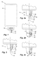
- Fig. 1 shows a drop dispenser according to the invention in an overall view.
- the drop dispenser 10 has a liquid reservoir 12, which is designed as a squeeze bottle.
- an outlet unit 14 of the drop dispenser 10 is directed downwards.
- This outlet unit has an outlet opening 16, which is closed by a valve pin in the closed state of the dispenser 10.
- the valve pin is part of an in Fig. 1 indicated by dashed lines valve 18, which opens and closes depending on the fluid pressure within the drop dispenser 10.
- the liquid reservoir 12 is compressed manually. This causes an increase in pressure and opening of the valve 18 by displacement of the valve pin.
- the exiting liquid collects as intended in the region of the outlet opening 16 and forms there a drop, which dissolves after reaching a certain size for the most part from the dispenser, while a smaller part, called residual drops, remains in the region of the outer surface of the outlet unit 14.
- the Fig. 2a to 2c show the outlet unit 14 of the donor the Fig. 1 in enlarged form.
- the structural design of the outlet unit 14 is explained in more detail.
- the lateral surface 32 of the conical portion 30 serves as intended the adhesion of a drop to be dispensed before it dissolves from the drop dispenser 10.
- the adhesion of this drop serve the end face 34 and the inner surface 36 which surround the outlet opening 16.
- the surfaces 32, 34, 36 are made hydrophilic.
- Fig. 2a, 2b and 2c this is illustrated by the dashed line drawn here.
- the surface of the one-piece body forming both the cone portion 30 and the cone portion 20 is made hydrophilic by a coating 50 or alternatively by irradiation.
- the lateral surface 22 of the upper frusto-conical section 20 adjacent to the lateral surface 32 is not made hydrophilic but has an unchanged material surface.
- the material of the truncated cone sections 20, 30 forming component may be, for example, HDPE. This is not hydrophilic material, so that a contact angle with water as a liquid in about 80 °. In the area of the hydrophilic surfaces 32, 34, 36, this contact angle is less than 5 ° due to the coating.
- a sharp-edged boundary edge 28 is provided which has a radius of curvature of about 0.2 mm. This boundary edge supports the following explained operation when discharging a drop.
- Fig. 2b shows the process of droplet production.
- the liquid is forced through the discharge opening 16 when the outlet valve is slightly open and accumulates in the in Fig. 2b sketched way.
- the liquid on the outside of the lateral surface 32 along this creeps up, but the boundary edge 28 due to the geometric design and due to the hydrophobic formation of the lateral surface 22 does not exceed.
- the outer diameter 2 of the droplet forming surface is clearly defined.
- the residual drop 42 according to Fig. 2c will therefore evaporate quickly.
- this is also responsible for the fact that as it were a substantial part of the internal volume of the residual droplet 42 is filled by the cone portion 30.
- Fig. 3 shows an alternative design that matches in terms of their operation with the previous design.
- the peculiarity of the design according to Fig. 3 is that the lateral surface 32, the end face 34 and the outlet opening 16 toward the facing surface 36 are provided on a separate housing portion forming a separate body 30 ', which consists of a hydrophilic in itself Material exists. This material may, for example, have been rendered hydrophilic by incorporated additives.
- This separate body 30 ' is inserted into a recess of a casing section 20' forming the lateral surface 22 and held there, for example, by a press fit.
- Fig. 4a to 4c again resemble the embodiment of Fig. 2a to 2c because here too a one-piece body forming the outside of the outlet unit 14 is provided which is only partially provided with a coating 50 which leads to hydrophilic properties.
- the outer surface of the outlet unit 14 has the shape of a spherical cap 30 ", the outside of which is provided in the manner mentioned with the coating 50.
- the effect of this outer coating and said shaping is similar to that in terms of Fig. 2a to 2c described effect. Again, it can be achieved by the enlarged surface, that a residual drop that remains after the discharge, can evaporate quickly.
- Fig. 4b and 4c The peculiarity of the spherical cap surface results in particular from the Fig. 4b and 4c , It will be appreciated that the spherical cap shape causes the volume of the forming drop 40 and the size of the drop 40 at the moment of detachment from the drop dispenser 10 to no longer depend on the precise orientation of the drop dispenser. So shows Fig. 4c in that even when the drop dispenser 10 is tilted by approximately 15 °, the volume of the drop is not affected. Thus, even with not very precise handling of the drop dispenser 10 ensures accurate dosing.
Landscapes
- Health & Medical Sciences (AREA)
- Engineering & Computer Science (AREA)
- Mechanical Engineering (AREA)
- Clinical Laboratory Science (AREA)
- Chemical & Material Sciences (AREA)
- Chemical Kinetics & Catalysis (AREA)
- Vascular Medicine (AREA)
- Heart & Thoracic Surgery (AREA)
- Biomedical Technology (AREA)
- Life Sciences & Earth Sciences (AREA)
- Animal Behavior & Ethology (AREA)
- General Health & Medical Sciences (AREA)
- Public Health (AREA)
- Veterinary Medicine (AREA)
- Ophthalmology & Optometry (AREA)
- Containers And Packaging Bodies Having A Special Means To Remove Contents (AREA)
- Closures For Containers (AREA)
- Medical Preparation Storing Or Oral Administration Devices (AREA)
- Infusion, Injection, And Reservoir Apparatuses (AREA)
Applications Claiming Priority (1)
| Application Number | Priority Date | Filing Date | Title |
|---|---|---|---|
| DE102011083355A DE102011083355B4 (de) | 2011-09-23 | 2011-09-23 | Tropfenspender |
Publications (2)
| Publication Number | Publication Date |
|---|---|
| EP2573005A1 true EP2573005A1 (fr) | 2013-03-27 |
| EP2573005B1 EP2573005B1 (fr) | 2017-11-01 |
Family
ID=46826312
Family Applications (1)
| Application Number | Title | Priority Date | Filing Date |
|---|---|---|---|
| EP12183511.0A Not-in-force EP2573005B1 (fr) | 2011-09-23 | 2012-09-07 | Distributeur compte-gouttes |
Country Status (4)
| Country | Link |
|---|---|
| US (1) | US8770448B2 (fr) |
| EP (1) | EP2573005B1 (fr) |
| JP (1) | JP6146850B2 (fr) |
| DE (1) | DE102011083355B4 (fr) |
Families Citing this family (8)
| Publication number | Priority date | Publication date | Assignee | Title |
|---|---|---|---|---|
| ES2952616T3 (es) | 2012-07-26 | 2023-11-02 | Allergan Inc | Sistema de tapa dual para cierres de recipiente para mantener la esterilidad de puntas durante su almacenamiento en estantes |
| DE102012214426B3 (de) | 2012-08-14 | 2013-08-01 | Aptar Radolfzell Gmbh | Tropfenspender |
| GB2554547B (en) * | 2015-05-18 | 2021-04-28 | Aptargroup Inc | Dispensing closure |
| EP3521797B1 (fr) * | 2016-09-30 | 2021-06-23 | FUJIFILM Corporation | Buse et récipient de distribution |
| US10961028B1 (en) | 2017-03-15 | 2021-03-30 | Allen Brothers & Rosselot Inc. | Liquid dispenser for a bottle |
| EP3730220B1 (fr) * | 2019-04-26 | 2022-07-06 | Aptar Radolfzell GmbH | Distributeur destiné à la sortie des liquides pharmaceutiques |
| DE102022102476B3 (de) | 2022-02-02 | 2023-02-02 | Silgan Dispensing Systems Hemer Gmbh | Tropfenspender zur Abgabe einer pharmazeutischen Flüssigkeit |
| WO2024044388A1 (fr) * | 2022-08-25 | 2024-02-29 | Twenty Twenty Therapeutics Llc | Buse pour dispositif de distribution de fluide ophtalmique |
Citations (6)
| Publication number | Priority date | Publication date | Assignee | Title |
|---|---|---|---|---|
| WO1984000707A1 (fr) * | 1982-08-12 | 1984-03-01 | American Hospital Supply Corp | Procede et bouteille de distribution |
| EP0401022A1 (fr) * | 1989-06-01 | 1990-12-05 | Pall Corporation | Distributeur et doseur de liquide, propre à éviter la contamination |
| EP0431885A1 (fr) * | 1989-12-08 | 1991-06-12 | LABORATOIRES MERCK, SHARP & DOHME-CHIBRET | Embout compte-gouttes pour distribuer un produit liquide, notamment collyres |
| DE112006001297T5 (de) | 2005-06-02 | 2008-04-17 | Institut "Jozef Stefan" | Verfahren und Vorrichtung zur lokalen Funktionalisierung von Polymermaterialien |
| WO2008068775A2 (fr) * | 2006-12-07 | 2008-06-12 | Sun Pharmaceutical Industries Limited | Compte-gouttes pour distribuer des quantités en microlitres d'un liquide sous la forme d'une gouttelette |
| DE102007049587A1 (de) | 2007-10-15 | 2009-04-16 | Evonik Degussa Gmbh | Hydrophilierte, hyperverzweigte Polyurethane |
Family Cites Families (15)
| Publication number | Priority date | Publication date | Assignee | Title |
|---|---|---|---|---|
| JPH0651135B2 (ja) * | 1986-03-25 | 1994-07-06 | 松下電工株式会社 | スチ−ム発生装置のノズル |
| US5221017A (en) * | 1992-10-13 | 1993-06-22 | Wheaton Holding, Inc. | Controlled dropper tip closure |
| US5373964A (en) * | 1993-06-23 | 1994-12-20 | Moore; Sidney D. | Eyedrop dispenser with focusing liquid lens |
| US7008979B2 (en) * | 2002-04-30 | 2006-03-07 | Hydromer, Inc. | Coating composition for multiple hydrophilic applications |
| JP3971329B2 (ja) * | 2002-10-23 | 2007-09-05 | ロート製薬株式会社 | 液体用容器のノズル構造 |
| JP4099379B2 (ja) * | 2002-12-02 | 2008-06-11 | 東亜ディーケーケー株式会社 | 液滴計量採集装置 |
| US6869421B2 (en) * | 2002-12-09 | 2005-03-22 | Gary L. Hanley | Device for non-gravity presentation of a liquid droplet |
| CN1845856A (zh) * | 2003-09-02 | 2006-10-11 | 大塚制药株式会社 | 排出构件、具有该排出构件的排出容器和点眼容器 |
| ITRM20040524A1 (it) * | 2004-10-22 | 2005-01-22 | Federigo Federighi | Flacone erogatore multidose per preparati liquidi senza conservanti. |
| JP3861901B2 (ja) * | 2004-12-28 | 2006-12-27 | ダイキン工業株式会社 | 静電噴霧装置 |
| KR200385091Y1 (ko) * | 2005-03-14 | 2005-05-24 | 주식회사 천경 | 내용물출구 개폐가 가능한 화장품 용기 |
| JP2007007324A (ja) * | 2005-07-04 | 2007-01-18 | Fine Plus:Kk | 滴下ノズル及び保存容器 |
| DE102005056488A1 (de) * | 2005-11-21 | 2007-05-24 | Ing. Erich Pfeiffer Gmbh | Spender und Dosierbaugruppe für die Mediumdosierung |
| JP2008232741A (ja) * | 2007-03-19 | 2008-10-02 | Horiba Ltd | 液体流量センサ、これを用いた清浄水供給システムおよび試料中の酸化セレン除去装置、およびこれらを用いた石炭燃焼排気ガス中の水銀測定装置 |
| US20100006600A1 (en) * | 2008-07-14 | 2010-01-14 | Dascanio Gustavo A | Fluid dispenser including hydrophobic ring |
-
2011
- 2011-09-23 DE DE102011083355A patent/DE102011083355B4/de active Active
-
2012
- 2012-09-07 EP EP12183511.0A patent/EP2573005B1/fr not_active Not-in-force
- 2012-09-19 US US13/622,665 patent/US8770448B2/en active Active
- 2012-09-21 JP JP2012207736A patent/JP6146850B2/ja active Active
Patent Citations (6)
| Publication number | Priority date | Publication date | Assignee | Title |
|---|---|---|---|---|
| WO1984000707A1 (fr) * | 1982-08-12 | 1984-03-01 | American Hospital Supply Corp | Procede et bouteille de distribution |
| EP0401022A1 (fr) * | 1989-06-01 | 1990-12-05 | Pall Corporation | Distributeur et doseur de liquide, propre à éviter la contamination |
| EP0431885A1 (fr) * | 1989-12-08 | 1991-06-12 | LABORATOIRES MERCK, SHARP & DOHME-CHIBRET | Embout compte-gouttes pour distribuer un produit liquide, notamment collyres |
| DE112006001297T5 (de) | 2005-06-02 | 2008-04-17 | Institut "Jozef Stefan" | Verfahren und Vorrichtung zur lokalen Funktionalisierung von Polymermaterialien |
| WO2008068775A2 (fr) * | 2006-12-07 | 2008-06-12 | Sun Pharmaceutical Industries Limited | Compte-gouttes pour distribuer des quantités en microlitres d'un liquide sous la forme d'une gouttelette |
| DE102007049587A1 (de) | 2007-10-15 | 2009-04-16 | Evonik Degussa Gmbh | Hydrophilierte, hyperverzweigte Polyurethane |
Also Published As
| Publication number | Publication date |
|---|---|
| DE102011083355A1 (de) | 2013-03-28 |
| EP2573005B1 (fr) | 2017-11-01 |
| DE102011083355B4 (de) | 2013-04-11 |
| US8770448B2 (en) | 2014-07-08 |
| JP6146850B2 (ja) | 2017-06-14 |
| US20130075431A1 (en) | 2013-03-28 |
| JP2013066712A (ja) | 2013-04-18 |
Similar Documents
| Publication | Publication Date | Title |
|---|---|---|
| EP2573005B1 (fr) | Distributeur compte-gouttes | |
| EP1698399B1 (fr) | Couvercle perforé de sortie pour appareil de distribution d'un fluide à haute viscosité | |
| DE602004011986T2 (de) | Fluidproduktsprühkopf und diesen sprühkopf umfassende abgabepumpe | |
| EP2130610A1 (fr) | Dispositif de sortie | |
| EP1810593B1 (fr) | Unité cosmétique | |
| EP2600983B1 (fr) | Distributeur doseur | |
| DE102004050679A1 (de) | Dosiervorrichtung | |
| EP0590293B1 (fr) | Coiffe pour récipients, spécialement pour flacons distributeurs | |
| EP2698134B1 (fr) | Distributeur compte-gouttes | |
| CH712432A1 (de) | Tube mit Drosseleinsatz. | |
| EP3736049A1 (fr) | Tête distributrice et distributeur de liquide comprenant une tête distributrice | |
| CH656513A5 (de) | Stabfoermige dispensiervorrichtung. | |
| DE29914452U1 (de) | Rollkugelspender | |
| EP3733305B1 (fr) | Applicateur d'adhésif et ensemble destiné au stockage et à l'utilisation d'un adhésif | |
| EP3837063B1 (fr) | Emballage sous forme de boîte, ainsi que dispositif et procédé pour la fabrication de son ébauche | |
| DE102017106262B4 (de) | Fließpressverfahren mit Fließpressgesenk und Fließpressstempel zur Herstellung von Hohlkörpern, bestehend aus einem metallischen Werkstoff, sowie Fließpresswerkzeug | |
| DE2449516C3 (de) | Flaschenverschluß mit einem Ausgießkörper | |
| AT503942A4 (de) | Flaschenverschluss | |
| EP3992110B1 (fr) | Dispositif de dosage | |
| EP4338774A1 (fr) | Tête de distribution pour un distributeur de liquide et distributeur de liquide doté d'une telle tête de distribution | |
| DE202009007151U1 (de) | Farbflasche für eine Airbrush-Sprühpistole | |
| EP4667384A1 (fr) | Boîte sous pression à colonne montante modifiée | |
| DE202024106577U1 (de) | Behälter zur dosierten Abgabe einer Flüssigkeit | |
| WO2021089283A1 (fr) | Corps tubulaire à pied de support | |
| CH719875A2 (de) | Pumpaufsatz für einen Flüssigkeitsspender. |
Legal Events
| Date | Code | Title | Description |
|---|---|---|---|
| PUAI | Public reference made under article 153(3) epc to a published international application that has entered the european phase |
Free format text: ORIGINAL CODE: 0009012 |
|
| AK | Designated contracting states |
Kind code of ref document: A1 Designated state(s): AL AT BE BG CH CY CZ DE DK EE ES FI FR GB GR HR HU IE IS IT LI LT LU LV MC MK MT NL NO PL PT RO RS SE SI SK SM TR |
|
| AX | Request for extension of the european patent |
Extension state: BA ME |
|
| 17P | Request for examination filed |
Effective date: 20130925 |
|
| RBV | Designated contracting states (corrected) |
Designated state(s): AL AT BE BG CH CY CZ DE DK EE ES FI FR GB GR HR HU IE IS IT LI LT LU LV MC MK MT NL NO PL PT RO RS SE SI SK SM TR |
|
| RIC1 | Information provided on ipc code assigned before grant |
Ipc: A61F 9/00 20060101ALI20170329BHEP Ipc: B01L 3/00 20060101ALI20170329BHEP Ipc: B65D 47/18 20060101AFI20170329BHEP Ipc: B65D 47/20 20060101ALI20170329BHEP |
|
| GRAP | Despatch of communication of intention to grant a patent |
Free format text: ORIGINAL CODE: EPIDOSNIGR1 |
|
| INTG | Intention to grant announced |
Effective date: 20170524 |
|
| GRAS | Grant fee paid |
Free format text: ORIGINAL CODE: EPIDOSNIGR3 |
|
| RBV | Designated contracting states (corrected) |
Designated state(s): AL AT BE BG CH CY CZ DK EE ES FI FR GB GR HR HU IE IS IT LI LT LU LV MC MK MT NL NO PL PT RO RS SE SI SK SM TR |
|
| REG | Reference to a national code |
Ref country code: DE Ref legal event code: R108 |
|
| GRAA | (expected) grant |
Free format text: ORIGINAL CODE: 0009210 |
|
| AK | Designated contracting states |
Kind code of ref document: B1 Designated state(s): AL AT BE BG CH CY CZ DK EE ES FI FR GB GR HR HU IE IS IT LI LT LU LV MC MK MT NL NO PL PT RO RS SE SI SK SM TR |
|
| REG | Reference to a national code |
Ref country code: GB Ref legal event code: FG4D Free format text: NOT ENGLISH |
|
| REG | Reference to a national code |
Ref country code: CH Ref legal event code: EP Ref country code: AT Ref legal event code: REF Ref document number: 941777 Country of ref document: AT Kind code of ref document: T Effective date: 20171115 |
|
| REG | Reference to a national code |
Ref country code: IE Ref legal event code: FG4D Free format text: LANGUAGE OF EP DOCUMENT: GERMAN |
|
| REG | Reference to a national code |
Ref country code: CH Ref legal event code: NV Representative=s name: DR. LUSUARDI AG, CH |
|
| REG | Reference to a national code |
Ref country code: NL Ref legal event code: MP Effective date: 20171101 |
|
| REG | Reference to a national code |
Ref country code: LT Ref legal event code: MG4D |
|
| PG25 | Lapsed in a contracting state [announced via postgrant information from national office to epo] |
Ref country code: NL Free format text: LAPSE BECAUSE OF FAILURE TO SUBMIT A TRANSLATION OF THE DESCRIPTION OR TO PAY THE FEE WITHIN THE PRESCRIBED TIME-LIMIT Effective date: 20171101 Ref country code: FI Free format text: LAPSE BECAUSE OF FAILURE TO SUBMIT A TRANSLATION OF THE DESCRIPTION OR TO PAY THE FEE WITHIN THE PRESCRIBED TIME-LIMIT Effective date: 20171101 Ref country code: LT Free format text: LAPSE BECAUSE OF FAILURE TO SUBMIT A TRANSLATION OF THE DESCRIPTION OR TO PAY THE FEE WITHIN THE PRESCRIBED TIME-LIMIT Effective date: 20171101 Ref country code: ES Free format text: LAPSE BECAUSE OF FAILURE TO SUBMIT A TRANSLATION OF THE DESCRIPTION OR TO PAY THE FEE WITHIN THE PRESCRIBED TIME-LIMIT Effective date: 20171101 Ref country code: SE Free format text: LAPSE BECAUSE OF FAILURE TO SUBMIT A TRANSLATION OF THE DESCRIPTION OR TO PAY THE FEE WITHIN THE PRESCRIBED TIME-LIMIT Effective date: 20171101 Ref country code: NO Free format text: LAPSE BECAUSE OF FAILURE TO SUBMIT A TRANSLATION OF THE DESCRIPTION OR TO PAY THE FEE WITHIN THE PRESCRIBED TIME-LIMIT Effective date: 20180201 |
|
| PG25 | Lapsed in a contracting state [announced via postgrant information from national office to epo] |
Ref country code: HR Free format text: LAPSE BECAUSE OF FAILURE TO SUBMIT A TRANSLATION OF THE DESCRIPTION OR TO PAY THE FEE WITHIN THE PRESCRIBED TIME-LIMIT Effective date: 20171101 Ref country code: GR Free format text: LAPSE BECAUSE OF FAILURE TO SUBMIT A TRANSLATION OF THE DESCRIPTION OR TO PAY THE FEE WITHIN THE PRESCRIBED TIME-LIMIT Effective date: 20180202 Ref country code: BG Free format text: LAPSE BECAUSE OF FAILURE TO SUBMIT A TRANSLATION OF THE DESCRIPTION OR TO PAY THE FEE WITHIN THE PRESCRIBED TIME-LIMIT Effective date: 20180201 Ref country code: RS Free format text: LAPSE BECAUSE OF FAILURE TO SUBMIT A TRANSLATION OF THE DESCRIPTION OR TO PAY THE FEE WITHIN THE PRESCRIBED TIME-LIMIT Effective date: 20171101 Ref country code: LV Free format text: LAPSE BECAUSE OF FAILURE TO SUBMIT A TRANSLATION OF THE DESCRIPTION OR TO PAY THE FEE WITHIN THE PRESCRIBED TIME-LIMIT Effective date: 20171101 Ref country code: IS Free format text: LAPSE BECAUSE OF FAILURE TO SUBMIT A TRANSLATION OF THE DESCRIPTION OR TO PAY THE FEE WITHIN THE PRESCRIBED TIME-LIMIT Effective date: 20180301 |
|
| PG25 | Lapsed in a contracting state [announced via postgrant information from national office to epo] |
Ref country code: CY Free format text: LAPSE BECAUSE OF FAILURE TO SUBMIT A TRANSLATION OF THE DESCRIPTION OR TO PAY THE FEE WITHIN THE PRESCRIBED TIME-LIMIT Effective date: 20171101 Ref country code: EE Free format text: LAPSE BECAUSE OF FAILURE TO SUBMIT A TRANSLATION OF THE DESCRIPTION OR TO PAY THE FEE WITHIN THE PRESCRIBED TIME-LIMIT Effective date: 20171101 Ref country code: DK Free format text: LAPSE BECAUSE OF FAILURE TO SUBMIT A TRANSLATION OF THE DESCRIPTION OR TO PAY THE FEE WITHIN THE PRESCRIBED TIME-LIMIT Effective date: 20171101 Ref country code: SK Free format text: LAPSE BECAUSE OF FAILURE TO SUBMIT A TRANSLATION OF THE DESCRIPTION OR TO PAY THE FEE WITHIN THE PRESCRIBED TIME-LIMIT Effective date: 20171101 Ref country code: CZ Free format text: LAPSE BECAUSE OF FAILURE TO SUBMIT A TRANSLATION OF THE DESCRIPTION OR TO PAY THE FEE WITHIN THE PRESCRIBED TIME-LIMIT Effective date: 20171101 |
|
| PG25 | Lapsed in a contracting state [announced via postgrant information from national office to epo] |
Ref country code: PL Free format text: LAPSE BECAUSE OF FAILURE TO SUBMIT A TRANSLATION OF THE DESCRIPTION OR TO PAY THE FEE WITHIN THE PRESCRIBED TIME-LIMIT Effective date: 20171101 Ref country code: RO Free format text: LAPSE BECAUSE OF FAILURE TO SUBMIT A TRANSLATION OF THE DESCRIPTION OR TO PAY THE FEE WITHIN THE PRESCRIBED TIME-LIMIT Effective date: 20171101 Ref country code: SM Free format text: LAPSE BECAUSE OF FAILURE TO SUBMIT A TRANSLATION OF THE DESCRIPTION OR TO PAY THE FEE WITHIN THE PRESCRIBED TIME-LIMIT Effective date: 20171101 |
|
| PLBE | No opposition filed within time limit |
Free format text: ORIGINAL CODE: 0009261 |
|
| STAA | Information on the status of an ep patent application or granted ep patent |
Free format text: STATUS: NO OPPOSITION FILED WITHIN TIME LIMIT |
|
| REG | Reference to a national code |
Ref country code: FR Ref legal event code: PLFP Year of fee payment: 7 |
|
| PG25 | Lapsed in a contracting state [announced via postgrant information from national office to epo] |
Ref country code: MT Free format text: LAPSE BECAUSE OF FAILURE TO SUBMIT A TRANSLATION OF THE DESCRIPTION OR TO PAY THE FEE WITHIN THE PRESCRIBED TIME-LIMIT Effective date: 20171101 |
|
| 26N | No opposition filed |
Effective date: 20180802 |
|
| PG25 | Lapsed in a contracting state [announced via postgrant information from national office to epo] |
Ref country code: SI Free format text: LAPSE BECAUSE OF FAILURE TO SUBMIT A TRANSLATION OF THE DESCRIPTION OR TO PAY THE FEE WITHIN THE PRESCRIBED TIME-LIMIT Effective date: 20171101 |
|
| PG25 | Lapsed in a contracting state [announced via postgrant information from national office to epo] |
Ref country code: MC Free format text: LAPSE BECAUSE OF FAILURE TO SUBMIT A TRANSLATION OF THE DESCRIPTION OR TO PAY THE FEE WITHIN THE PRESCRIBED TIME-LIMIT Effective date: 20171101 |
|
| REG | Reference to a national code |
Ref country code: BE Ref legal event code: MM Effective date: 20180930 |
|
| REG | Reference to a national code |
Ref country code: IE Ref legal event code: MM4A |
|
| PG25 | Lapsed in a contracting state [announced via postgrant information from national office to epo] |
Ref country code: LU Free format text: LAPSE BECAUSE OF NON-PAYMENT OF DUE FEES Effective date: 20180907 |
|
| PG25 | Lapsed in a contracting state [announced via postgrant information from national office to epo] |
Ref country code: IE Free format text: LAPSE BECAUSE OF NON-PAYMENT OF DUE FEES Effective date: 20180907 |
|
| PG25 | Lapsed in a contracting state [announced via postgrant information from national office to epo] |
Ref country code: BE Free format text: LAPSE BECAUSE OF NON-PAYMENT OF DUE FEES Effective date: 20180930 |
|
| PGFP | Annual fee paid to national office [announced via postgrant information from national office to epo] |
Ref country code: IT Payment date: 20190920 Year of fee payment: 8 Ref country code: FR Payment date: 20190923 Year of fee payment: 8 |
|
| REG | Reference to a national code |
Ref country code: AT Ref legal event code: MM01 Ref document number: 941777 Country of ref document: AT Kind code of ref document: T Effective date: 20180907 |
|
| PGFP | Annual fee paid to national office [announced via postgrant information from national office to epo] |
Ref country code: GB Payment date: 20190924 Year of fee payment: 8 |
|
| PG25 | Lapsed in a contracting state [announced via postgrant information from national office to epo] |
Ref country code: AT Free format text: LAPSE BECAUSE OF NON-PAYMENT OF DUE FEES Effective date: 20180907 |
|
| PGFP | Annual fee paid to national office [announced via postgrant information from national office to epo] |
Ref country code: CH Payment date: 20190924 Year of fee payment: 8 |
|
| PG25 | Lapsed in a contracting state [announced via postgrant information from national office to epo] |
Ref country code: TR Free format text: LAPSE BECAUSE OF FAILURE TO SUBMIT A TRANSLATION OF THE DESCRIPTION OR TO PAY THE FEE WITHIN THE PRESCRIBED TIME-LIMIT Effective date: 20171101 |
|
| PG25 | Lapsed in a contracting state [announced via postgrant information from national office to epo] |
Ref country code: HU Free format text: LAPSE BECAUSE OF FAILURE TO SUBMIT A TRANSLATION OF THE DESCRIPTION OR TO PAY THE FEE WITHIN THE PRESCRIBED TIME-LIMIT; INVALID AB INITIO Effective date: 20120907 Ref country code: PT Free format text: LAPSE BECAUSE OF FAILURE TO SUBMIT A TRANSLATION OF THE DESCRIPTION OR TO PAY THE FEE WITHIN THE PRESCRIBED TIME-LIMIT Effective date: 20171101 |
|
| PG25 | Lapsed in a contracting state [announced via postgrant information from national office to epo] |
Ref country code: MK Free format text: LAPSE BECAUSE OF NON-PAYMENT OF DUE FEES Effective date: 20171101 |
|
| PG25 | Lapsed in a contracting state [announced via postgrant information from national office to epo] |
Ref country code: AL Free format text: LAPSE BECAUSE OF FAILURE TO SUBMIT A TRANSLATION OF THE DESCRIPTION OR TO PAY THE FEE WITHIN THE PRESCRIBED TIME-LIMIT Effective date: 20171101 |
|
| REG | Reference to a national code |
Ref country code: CH Ref legal event code: PL |
|
| GBPC | Gb: european patent ceased through non-payment of renewal fee |
Effective date: 20200907 |
|
| PG25 | Lapsed in a contracting state [announced via postgrant information from national office to epo] |
Ref country code: FR Free format text: LAPSE BECAUSE OF NON-PAYMENT OF DUE FEES Effective date: 20200930 |
|
| PG25 | Lapsed in a contracting state [announced via postgrant information from national office to epo] |
Ref country code: GB Free format text: LAPSE BECAUSE OF NON-PAYMENT OF DUE FEES Effective date: 20200907 Ref country code: LI Free format text: LAPSE BECAUSE OF NON-PAYMENT OF DUE FEES Effective date: 20200930 Ref country code: CH Free format text: LAPSE BECAUSE OF NON-PAYMENT OF DUE FEES Effective date: 20200930 |
|
| PG25 | Lapsed in a contracting state [announced via postgrant information from national office to epo] |
Ref country code: IT Free format text: LAPSE BECAUSE OF NON-PAYMENT OF DUE FEES Effective date: 20200907 |