EP2573017A2 - Garnwickeleinheit, Garnwickelvorrichtung und Spinnmaschine - Google Patents
Garnwickeleinheit, Garnwickelvorrichtung und Spinnmaschine Download PDFInfo
- Publication number
- EP2573017A2 EP2573017A2 EP12174300A EP12174300A EP2573017A2 EP 2573017 A2 EP2573017 A2 EP 2573017A2 EP 12174300 A EP12174300 A EP 12174300A EP 12174300 A EP12174300 A EP 12174300A EP 2573017 A2 EP2573017 A2 EP 2573017A2
- Authority
- EP
- European Patent Office
- Prior art keywords
- yarn
- spun
- winding
- pooling
- spun yarn
- Prior art date
- Legal status (The legal status is an assumption and is not a legal conclusion. Google has not performed a legal analysis and makes no representation as to the accuracy of the status listed.)
- Granted
Links
- 238000009987 spinning Methods 0.000 title claims abstract description 125
- 238000004804 winding Methods 0.000 title claims abstract description 116
- 238000011176 pooling Methods 0.000 claims abstract description 119
- 239000000835 fiber Substances 0.000 claims description 21
- 230000002093 peripheral effect Effects 0.000 claims description 13
- 238000012806 monitoring device Methods 0.000 claims description 9
- 238000012544 monitoring process Methods 0.000 claims description 4
- 238000007664 blowing Methods 0.000 description 13
- 238000011144 upstream manufacturing Methods 0.000 description 12
- 230000007547 defect Effects 0.000 description 11
- 238000001514 detection method Methods 0.000 description 11
- 230000005856 abnormality Effects 0.000 description 6
- 230000002159 abnormal effect Effects 0.000 description 4
- 238000010042 air jet spinning Methods 0.000 description 4
- 238000000034 method Methods 0.000 description 3
- 230000003287 optical effect Effects 0.000 description 3
- 230000007423 decrease Effects 0.000 description 1
- 230000002950 deficient Effects 0.000 description 1
- 238000012986 modification Methods 0.000 description 1
- 230000004048 modification Effects 0.000 description 1
- 239000002994 raw material Substances 0.000 description 1
Images


Classifications
-
- B—PERFORMING OPERATIONS; TRANSPORTING
- B65—CONVEYING; PACKING; STORING; HANDLING THIN OR FILAMENTARY MATERIAL
- B65H—HANDLING THIN OR FILAMENTARY MATERIAL, e.g. SHEETS, WEBS, CABLES
- B65H63/00—Warning or safety devices, e.g. automatic fault detectors, stop-motions ; Quality control of the package
- B65H63/06—Warning or safety devices, e.g. automatic fault detectors, stop-motions ; Quality control of the package responsive to presence of irregularities in running material, e.g. for severing the material at irregularities ; Control of the correct working of the yarn cleaner
-
- B—PERFORMING OPERATIONS; TRANSPORTING
- B65—CONVEYING; PACKING; STORING; HANDLING THIN OR FILAMENTARY MATERIAL
- B65H—HANDLING THIN OR FILAMENTARY MATERIAL, e.g. SHEETS, WEBS, CABLES
- B65H51/00—Forwarding filamentary material
- B65H51/20—Devices for temporarily storing filamentary material during forwarding, e.g. for buffer storage
- B65H51/22—Reels or cages, e.g. cylindrical, with storing and forwarding surfaces provided by rollers or bars
-
- B—PERFORMING OPERATIONS; TRANSPORTING
- B65—CONVEYING; PACKING; STORING; HANDLING THIN OR FILAMENTARY MATERIAL
- B65H—HANDLING THIN OR FILAMENTARY MATERIAL, e.g. SHEETS, WEBS, CABLES
- B65H54/00—Winding, coiling, or depositing filamentary material
- B65H54/70—Other constructional features of yarn-winding machines
- B65H54/71—Arrangements for severing filamentary materials
-
- B—PERFORMING OPERATIONS; TRANSPORTING
- B65—CONVEYING; PACKING; STORING; HANDLING THIN OR FILAMENTARY MATERIAL
- B65H—HANDLING THIN OR FILAMENTARY MATERIAL, e.g. SHEETS, WEBS, CABLES
- B65H69/00—Methods of, or devices for, interconnecting successive lengths of material; Knot-tying devices ;Control of the correct working of the interconnecting device
- B65H69/06—Methods of, or devices for, interconnecting successive lengths of material; Knot-tying devices ;Control of the correct working of the interconnecting device by splicing
-
- B—PERFORMING OPERATIONS; TRANSPORTING
- B65—CONVEYING; PACKING; STORING; HANDLING THIN OR FILAMENTARY MATERIAL
- B65H—HANDLING THIN OR FILAMENTARY MATERIAL, e.g. SHEETS, WEBS, CABLES
- B65H2701/00—Handled material; Storage means
- B65H2701/30—Handled filamentary material
- B65H2701/31—Textiles threads or artificial strands of filaments
-
- D—TEXTILES; PAPER
- D01—NATURAL OR MAN-MADE THREADS OR FIBRES; SPINNING
- D01H—SPINNING OR TWISTING
- D01H1/00—Spinning or twisting machines in which the product is wound-up continuously
- D01H1/11—Spinning by false-twisting
- D01H1/115—Spinning by false-twisting using pneumatic means
Definitions
- the present invention relates to a yarn winding unit that winds a spun yarn to form a package, a yarn winding apparatus and a spinning machine.
- Patent Document 1 This type of yarn winding apparatus is disclosed in, for example, Japanese Patent Application Laid-open No. 2010-77576 (Patent Document 1).
- the spinning machine disclosed in Patent Document 1 includes a plurality of spinning units.
- Each of the spinning units includes a spinning device that supplies a spun yarn and a winding device that winds the spun yarn and forms a package.
- a yarn slack eliminating device is arranged between the spinning device and the winding device.
- the yarn slack eliminating device temporarily pools the spun yarn around a rotating roller called a slack eliminating roller.
- a yarn clearer and a cutter are arranged between the spinning device and the yarn slack eliminating device.
- the yarn clearer monitors a thickness of the running spun yarn to detect any yarn defect. Upon detection of a yarn defect, the yarn clearer causes the cutter to cut the yarn to remove the yarn defect.
- the spinning machine disclosed in Patent Document 1 includes a yarn joining carrier.
- the yarn joining carrier includes a yarn joining device that joins the yarn on the spinning device side and the yarn on the package side.
- the yarn joining carrier moves to and stops at the position corresponding to the concerned spinning unit so that the yarn joining device can perform a yarn joining operation. Once the yarn joining operation is completed, the spinning operation of the spinning unit is resumed.
- the yarn slack eliminating device is arranged upstream of the yarn joining device in a yarn running direction, and the cutter is arranged further upstream of the yarn slack eliminating device. Therefore, even if a faulty yarn-joining is detected, the following operation needs to be undertaken to remove the faulty yarn joint. That is, the faulty yarn joint is cut by the cutter, and further, the entire spun yarn pooled in the yarn slack eliminating device is temporarily wound into the package. Thereafter, the package is rotated in the reverse direction to draw out the faulty yarn joint, and yarns are again joined by the yarn joining device after removing the faulty yarn joint.
- the spun yarn that is pooled in the yarn slack eliminating device can be of considerable length. Therefore, winding the entire spun yarn and again drawing the yarn up to the faulty yarn joint can take a long time.
- the present invention overcomes the prior art problems.
- a yarn winding apparatus includes a yarn supplying device, a winding device, a yarn joining device, a yarn pooling device, and a first cutting device.
- the yarn supplying device is adapted to supply a spun yarn.
- the winding device is adapted to wind the spun yarn onto a package.
- the yarn joining device is adapted to join an end of the spun yarn on the yarn supplying device side and an end of the spun yarn on the winding device side at a position between the yarn supplying device and the winding device in a yarn running direction.
- the yarn pooling device is adapted to temporarily pool the spun yarn at a position between the yarn supplying device and the yarn joining device in the yarn running direction.
- the first cutting device is adapted to cut the spun yarn at a position between the yarn pooling device and the yarn joining device in the yarn running direction.
- the length of the spun yarn that is wound by the winding device is shortened. Consequently, the length of the spun yarn that needs to be drawn from the package for a yarn joining operation by the yarn joining device is also shortened, and the yarn joining operation can be performed efficiently.
- the yarn winding apparatus includes a monitoring device adapted to monitor the spun yarn joined by the yarn joining device at a position immediately downstream of the yarn joining device in the yarn running direction.
- the first cutting device is adapted to cut the spun yarn based on a monitoring result obtained in the monitoring device.
- the spun yarn can be immediately cut by the first cutting device, and the yarn joining operation can be redone by the yarn joining device. Consequently, the package can be wound more efficiently.
- the yarn winding apparatus further includes a second cutting device and a removal device.
- the second cutting device is adapted to cut the spun yarn supplied from the yarn supplying device to the yarn pooling device.
- the removal device is adapted to remove the spun yarn pooled in the yarn pooling device.
- the spun yarn at the downstream of the yarn pooling device is cut by the first cutting device and the spun yarn at the upstream of the yarn pooling device is cut by the second cutting device. Consequently, the spun yarn pooled in the yarn pooling device can be removed easily by the removal device.
- the yarn pooling device in the yarn winding apparatus, includes a pooling roller adapted to pool the spun yarn by winding the spun yarn on an outer peripheral surface thereof.
- the yarn removal device includes a suction section and a driving section.
- the suction section is arranged near the yarn pooling device and adapted to suck in the spun yarn pooled in the yarn pooling device.
- the driving section is adapted to drive the yarn pooling device in the direction that assists the suction of the spun yarn by the suction section.
- the spun yarn can be removed definitively and in a short time.
- the yarn winding apparatus includes a detecting section adapted to detect whether the spun yarn is removed from the yarn pooling device.
- the yarn joining device is adapted to perform joining of the spun yarn when the detecting section detects that the spun yarn has been removed.
- the unnecessary spun yarn pooled in the yarn pooling device is prevented from getting in the way when the yarn joining device is performing the yarn joining operation. Consequently, failure of the yarn joining operation and a drop in the quality of the package can be prevented.
- the yarn supplying device be a spinning device that is adapted to use airflow to form the spun yarn from a fiber bundle.
- the spun yarn pooled in the yarn pooling device tends to be fairly long. Therefore, in the yarn winding apparatus of this kind, it is preferable that the spun yarn be cut between the yarn pooling device and the yarn joining device.
- the yarn winding apparatus includes a plurality of yarn winding units arranged side-by-side and a carrier.
- Each of the yarn winding units includes at least the yarn supplying device, the winding device, and the yarn pooling device.
- the carrier is adapted to move to the yarn winding units, and includes at least one of the first cutting device and the yarn joining device.
- the yarn joining operation by the yarn joining device can be performed efficiently so that the package can be wound more efficiently.
- a yarn winding unit includes a yarn supplying device, a winding device, a yarn joining device, a yarn pooling device, and a first cutting device.
- the yarn supplying device is adapted to supply the spun yarn.
- the winding device is adapted to wind the spun yarn onto the package.
- the yarn joining device is arranged at a position between the yarn supplying device and the winding device in the yarn running direction and adapted to join the end of the spun yarn on the yarn supplying device side and the end of the spun yarn on the winding device side.
- the yarn pooling device is arranged at a position between the yarn supplying device and the yarn joining device in the yarn running direction and adapted to temporarily pool the spun yarn.
- the first cutting device is arranged at a position between the yarn pooling device and the yarn joining device in the yarn running direction and adapted to cut the spun yarn.
- the length of the spun yarn that is wound by the winding device is shortened. Consequently, the length of the spun yarn that needs to be drawn from the package for the yarn joining operation by the yarn joining device is also shortened, and the yarn joining operation can be performed efficiently.
- the yarn winding unit includes a monitoring device adapted to monitor the spun yarn joined by the yarn joining device at a position immediately downstream of the yarn joining device in the yarn running direction.
- the first cutting device is adapted to cut the spun yarn based on the monitoring result obtained in the monitoring device.
- the spun yarn can be immediately cut by the first cutting device, and the yarn joining operation can be redone by the yarn joining device. Consequently, the package can be wound more efficiently.
- the yarn winding unit further includes a second cutting device and a removal device.
- the second cutting device is adapted to cut the spun yarn supplied from the yarn supplying device to the yarn pooling device.
- the removal device is adapted to remove the spun yarn pooled in the yarn pooling device.
- the spun yarn at the downstream of the yarn pooling device is cut by the first cutting device and the spun yarn at the upstream of the yarn pooling device is cut by the second cutting device. Consequently, the spun yarn pooled in the yarn pooling device can be removed easily by the removal device.
- the yarn pooling device in the yarn winding unit, includes a pooling roller adapted to pool the spun yarn by winding the spun yarn on an outer peripheral surface thereof.
- the yarn removal device includes a suction section and a driving section.
- the suction section is arranged near the yarn pooling device and adapted to suck in the spun yarn pooled in the yarn pooling device.
- the driving section is adapted to drive the yarn pooling device in the direction that assists the suction of the spun yarn by the suction section.
- the spun yarn can be removed definitively and in a short time.
- the yarn winding unit includes a detecting section adapted to detect whether the spun yarn is removed from the yarn pooling device.
- the yarn joining device is adapted to perform joining of the spun yarn when the detecting section detects that the spun yarn has been removed.
- the unnecessary spun yarn pooled in the yarn pooling device is prevented from getting in the way when the yarn joining device is performing the yarn joining operation. Consequently, failure of the yarn joining operation and a drop in the quality of the package can be prevented.
- the yarn supplying device be a spinning device that is adapted to use airflow to form the spun yarn from the fiber bundle.
- the spun yarn pooled in the yarn pooling device tends to be fairly long. Therefore, in the yarn winding unit of this kind, it is preferable that the spun yarn be cut between the yarn pooling device and the yarn joining device.
- the yarn winding apparatus includes a plurality of the yarn winding units.
- the yarn joining operation by the yarn joining device in each of the yarn winding units can be performed efficiently so that the package can be wound more efficiently.
- a spinning machine 1 as an example of a yarn winding apparatus shown in FIG. 1 includes a plurality of spinning units (yarn winding units) 2 arranged in a line, a yarn joining carrier (carrier) 3, a blower box 80, and a motor box 5.
- each of the spinning units 2 includes, arranged from upstream to downstream, a drafting device 7, a spinning device (yarn supplying device) 9, a yarn pooling device 12, and a winding device 13.
- the terms "upstream” and “downstream” used in this specification are upstream and downstream, respectively, with respect to a running direction of a fiber bundle 8 and a spun yarn 10 during spinning.
- the spinning device 9 spins the fiber bundle 8 fed from the drafting device 7 to form the spun yarn 10, and the winding device 13 winds the spun yarn 10 to form a package 45.
- the drafting device 7 is arranged near an upper end of a frame 6 of the spinning machine 1.
- the drafting device 7 includes, sequentially from the upstream side, four drafting rollers, namely, a back roller 16, a third roller 17, a middle roller 19 with an apron belt 18 made of rubber stretched over it, and a front roller 20.
- Each of the drafting rollers is driven to rotate at a predetermined speed.
- the drafting device 7 includes one roller each arranged opposing each of the drafting rollers.
- a sliver 15, which serves as a raw material for the fiber bundle 8, is fed into the drafting device 7 from a not shown sliver case via a not shown sliver guide.
- the drafting device 7 extends (drafts) the sliver 15 until a predetermined width is reached by feeding the sliver 15 sandwiched between the rotating drafting rollers and the opposing rollers to form the fiber bundle 8.
- the spinning device 9 is arranged immediately downstream of the front roller 20.
- the fiber bundle 8 drafted by the drafting device 7 is fed into the spinning device 9.
- the spinning device 9 twists the fiber bundle 8 fed from the drafting device 7 to form the spun yarn 10.
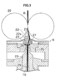
- the spinning device 9 used in the spinning machine 1 according to the present embodiment is an air-jet spinning device that twists the fiber bundle 8 by using a swirling airflow. As shown in FIG. 3 , the spinning device 9 includes a nozzle block 35, a hollow guide shaft 23, and a fiber guiding section 22.
- a spinning chamber 26 is formed between the nozzle block 35 and the hollow guide shaft 23.
- An air blowing nozzle 27 that blows air into the spinning chamber 26 is formed in the nozzle block 35.
- An introducing port 21 is formed in the fiber guiding section 22 for introducing the fiber bundle 8 into the spinning chamber 26.
- the air blowing nozzle 27 blows air into the spinning chamber 26 and produces the swirling airflow.
- the fiber bundle 8 that is fed from the drafting device 7 is guided into the spinning chamber 26 by the fiber guiding section 22 that includes the introducing port 21. Inside the spinning chamber 26, the fiber bundle 8 is swung around the hollow guide shaft 23 by the swirling airflow, and is twisted into a spun yarn 10. The twisted spun yarn 10 passes through a yarn path formed in the center of the hollow guide shaft 23, and is delivered outside of the spinning device 9 through a not shown yarn outlet at the downstream side.
- a guiding needle 22a with a tip thereof pointing inside the spinning chamber 26 is arranged in the introducing port 21.
- the fiber bundle 8 that is guided through the introducing port 21 is guided into the spinning chamber 26 via the guiding needle 22a.
- the guiding needle 22a need not be provided if the downstream end of the fiber guiding section 22 is able to perform the function of the guiding needle 22a.
- the winding device 13 is arranged downstream of the spinning device 9.
- the winding device 13 includes a cradle arm 71 that is pivotable about a support shaft 73.
- the cradle arm 71 rotatably supports a bobbin 48 onto which the spun yarn 10 is wound.
- the winding device 13 includes a winding drum 72 and a traverse device 75.
- the winding drum 72 is driven while being in contact with an outer peripheral surface of the bobbin 48 or an outer peripheral surface of the package 45 that is formed by winding the spun yarn 10 on the bobbin 48.
- the traverse device 75 includes a traverse guide 76 on which the spun yarn 10 can be engaged.
- a not shown electric motor drives the winding drum 72, thereby rotating the package 45 that is in contact with the winding drum 72.
- the traverse guide 76 is caused to reciprocate by a not shown driving mechanism.
- the winding device 13 winds the spun yarn 10 onto the package 45 while causing the spun yarn 10 to traverse.
- the yarn joining carrier 3 includes a yarn joining device 43, suction devices (a suction pipe 44 and a suction mouth 46), a yarn-joint quality monitor 47, a cutter 55, and a reverse driving mechanism 49.
- the reverse driving mechanism 49 includes a supporting arm 91 extendable from the yarn joining carrier 3 towards the winding device 13 or retractable, and a reverse roller 92 that is supported at the end of the supporting arm 91.
- the yarn joining carrier 3 travels on a rail 41 to and stops at the concerned spinning unit 2.
- the suction pipe 44 while turning upward and downward about an axis, holds by suction an end of the yarn coming out of the spinning device 9, and guides the end to the yarn joining device 43.
- the suction mouth 46 while turning upward and downward about an axis, holds by suction an end of the yarn from the package 45 that is supported by the winding device 13, and guides the end of the yarn to the yarn joining device 43.
- the cradle arm 71 is turned by a not shown driving mechanism so that the winding drum 72 and the package 45 are separated.
- the reverse driving mechanism 49 causes the reverse roller 92 to come into contact with the outer peripheral surface of the package 45 by causing the supporting arm 91 to extend toward the winding device 13.
- the reverse roller 92 is driven by a not shown motor, thereby causing the package 45 to rotate in a direction of unspooling the spun yarn 10.
- a time period for which the reverse roller 92 is driven is set such that, if the spun yarn 10 includes a portion that needs to be removed, a length of the spun yarn 10 sufficient enough to include that portion can be drawn into the suction mouth 46.
- the yarn joining device 43 joins the two ends of the yarn that are guided therein in this manner.
- the yarn-joint quality monitor (monitoring device) 47 that monitors the quality of the spun yarn 10 that is joined by the yarn joining device 43 is arranged immediately downstream of the yarn joining device 43.
- the quality of the yarn joining performed by the yarn joining device 43 is not always satisfactory.
- the yarn joining device 43 used in the present embodiment is of the type in which the yarn ends are untwisted before they are twisted and joined by the swirling airflow. Therefore, for example, the extent of untwisting of the end of the yarn, etc., can affect the quality of the yarn joint.
- the quality of the yarn joint is detected by the yarn-joint quality monitor 47, and if the quality does not satisfy a certain standard, the yarn joining device 43 performs the yarn joining operation again.
- the yarn-joint quality monitor 47 monitors a thickness of the spun yarn 10 that includes a portion where yarn-joining has been performed by the yarn joining device 43 by using a not shown optical sensor or electrostatic capacitance sensor. If any abnormality is detected in the thickness of the spun yarn 10, the yarn-joint quality monitor 47 sends a fault signal to a not shown unit controller.
- the cutter 55 is arranged immediately upstream of the yarn joining device 43.
- the unit controller controls the cutter 55 to immediately cut the spun yarn 10 so that the yarn joining operation can be redone. How the yarn joining operation is redone is explained in detail later.
- the yarn pooling device 12 is arranged between the spinning device 9 and the winding device 13. As shown in FIG. 2 , the yarn pooling device 12 includes a yarn pooling roller (pooling roller) 14 and an electric motor (driving section) 25 that drives the yarn pooling roller 14 to rotate.
- the yarn pooling roller 14 temporarily pools the spun yarn 10 by winding a specific quantity of the spun yarn 10 on an outer peripheral surface thereof. By causing the yarn pooling roller 14 to rotate at a predetermined rotation speed with the spun yarn 10 wound on the outer peripheral surface thereof, the spun yarn 10 can be drawn from the spinning device 9 and conveyed downstream at a predetermined speed. By temporarily pooling the spun yarn 10 on the outer peripheral surface of the yarn pooling roller 14, the yarn pooling device 12 functions as a kind of buffer between the spinning device 9 and the winding device 13. Accordingly, any problem (such as, a slack in the spun yarn 10) that arises due to a mismatch in a spinning speed of the spinning device 9 and a winding speed of the winding device 13 due to whatever reason can be resolved.
- the electric motor 25 normally rotates the yarn pooling roller 14 in a direction of spooling the spun yarn 10 on the yarn pooling roller 14, but can also rotate the yarn pooling roller 14 in the opposite direction, that is, in the direction of unspooling the spun yarn 10 from the yarn pooling roller 14.
- the yarn pooling device 12 includes a yarn detecting sensor (detecting section) 86 and a yarn sucking device (suction section) 87 that are arranged opposing the yarn pooling roller 14.
- the yarn detecting sensor 86 is a non-contact type optical sensor and is electrically connected to the unit controller.
- the yarn detecting sensor 86 detects whether the spun yarn 10 has been currently wound on the outer peripheral surface of the yarn pooling roller 14, and transmits a detection signal representing the detection result to the unit controller.
- the yarn sucking device 87 includes a suction pipe that is connected to a not shown blower arranged in the blower box 80.
- the opening of the suction pipe is located near the outer peripheral surface of the yarn pooling roller 14.
- the opening of the suction pipe is located facing near an upstream end of the yarn pooling roller 14.
- the yarn sucking device 87 creates a suction flow at the opening of the suction pipe and thereby is able to suck in and remove the spun yarn 10.
- a yarn removal device (removal device) 88 that removes the spun yarn 10 pooled in the yarn pooling device 12 includes the electric motor 25 that drives the yarn pooling roller 14 in the direction of unspooling the spun yarn 10 from the yarn pooling roller 14, and the yarn sucking device 87.
- a yarn-quality measuring equipment 59 is arranged between the spinning device 9 and the yarn pooling device 12.
- the spun yarn 10 spun by the spinning device 9 passes through the yarn-quality measuring equipment 59 before being wound in the yarn pooling device 12.
- the yarn-quality measuring equipment 59 has a structure that is similar to that of the yarn-joint quality monitor 47, and monitors the thickness of the running spun yarn 10 by using a not shown optical sensor or electrostatic capacitance sensor. Upon detection of a yarn defect (portion of the spun yarn 10 having abnormal thickness or the like) in the spun yarn 10, the yarn-quality measuring equipment 59 transmits a yarn defect detection signal to the not shown unit controller. The yarn-quality measuring equipment 59 can also detect the presence or absence of a foreign matter in the spun yarn 10 as the yarn defect.
- the unit controller controls the air blowing nozzle 27 to stop the blow of air.
- the spinning of the spun yarn 10 in the spinning device 9 is stopped. Consequently, the strength of the spun yarn 10 at the position of the spinning device 9 decreases, and the spun yarn 10 is cut at this position by tearing off.
- the air blowing nozzle 27 arranged in the spinning device 9 on the one hand spins the fiber bundle 8 to form the spun yarn 10 while on the other hand plays the role of cutting the spun yarn 10.
- the unit controller also stops the drafting by the drafting device 7.
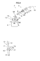
- FIG. 4 shows the cut spun yarn 10 in the state of being wound onto the package 45.
- the spun yarn 10 wound onto the package 45 includes the abnormal portion detected by the yarn-quality measuring equipment 59.
- the unit controller stops the winding operation of the winding device 13.
- the cradle arm 71 is made to slant as shown in FIG. 4 by a not shown cylinder, and the package 45 separates from the winding drum 72 that is always rotating.
- a not shown brake mechanism arranged in the winding device 13 acts on the package 45 so that the package 45 is brought to a complete stop after a certain degree of inertial rotation.
- the unit controller sends a control signal to the yarn joining carrier 3, causing the yarn joining carrier 3 to move to and stop at the location of the spinning unit 2 where the abnormality in the spun yarn 10 has been detected.
- the yarn joining device 43 takes a position between the spinning device 9 and the winding device 13 in the yarn running direction in the spinning unit 2.
- the yarn pooling device 12 takes a position between the spinning device 9 and the yarn joining device 43 in the yarn running direction
- the cutter 55 takes a position between the yarn pooling device 12 and the yarn joining device 43 in the yarn running direction.
- the unit controller When the yarn joining carrier 3 stops at the intended spinning unit 2, the unit controller causes the drafting device 7 to restart and the spinning by the spinning device 9 to be resumed.
- the unit controller sends the control signal to the yarn joining carrier 3, and the yarn joining carrier 3 causes the suction pipe 44 and the suction mouth 46 to turn, as shown in FIG. 5 , to hold by suction the yarn end on the spinning device 9 side and the yarn end on the package 45 side, respectively.
- the yarn joining carrier 3 causes the supporting arm 91 of the reverse driving mechanism 49 to extend to the winding device 13 side, causing the reverse roller 92 to come into contact with the package 45, and drives the reverse roller 92 to rotate in this state to rotate the package 45 in the reverse direction.
- a length of the spun yarn 10 on the package 45 side sufficient enough to include the abnormal portion wound onto the package 45 is drawn into the suction mouth 46 by suction.
- the yarn joining carrier 3 causes the suction pipe 44 and the suction mouth 46 to turn in the opposite direction to guide the held yarn ends to the yarn joining device 43, where yarn-joining is carried out.
- any excess spun yarn 10 is cut and removed by the yarn joining device 43.
- the abnormal portion detected by the yarn-quality measuring equipment 59 is also removed.
- the spinning device 9 continues to operate without stopping even during the yarn joining operation, because the spun yarn 10 formed by the spinning device 9 sequentially is pooled in the yarn pooling device 12, no slack occurs in the spun yarn 10.
- the cradle arm 71 that is slanting is returned to its original position, and as shown in FIG. 7 , the package 45 comes into contact with the winding drum 72, and the winding of the spun yarn 10 onto the package 45 resumes.
- the yarn path is guided by a not shown lever-like movable guide member, or suchlike, so that the spun yarn 10 passes through the yarn-joint quality monitor 47 and the cutter 55 immediately after the winding is resumed. Accordingly, the yarn joint formed by the yarn joining operation performed recently passes through the yarn-joint quality monitor 47 and the quality of the joint is monitored.
- the yarn-joint quality monitor 47 monitors the thickness of the running spun yarn 10. If a preset condition is satisfied, for example, that the thickness, etc., of the spun yarn 10 is greater than a standard value, the yarn-joint quality monitor 47 transmits the fault signal to the unit controller. In case the winding of the spun yarn 10 onto the package 45 proceeds to some extent and still the unit controller does not receive the fault signal, it signifies that the yarn joining performed by the yarn joining device 43 has been good. In this case, the unit controller controls the guiding member to cancel guiding of the yarn path so that the spun yarn 10 is not guided to pass through the yarn-joint quality monitor 47 and the cutter 55. In this manner, the spinning unit 2 returns to the normal state shown in FIG. 2 , and continues to wind the spun yarn 10 onto the package 45.
- the yarn-joint quality monitor 47 detects a faulty yarn joint in the state shown in FIG. 7 , and sends the fault signal to the unit controller is explained below.
- the unit controller Upon receiving the fault signal, the unit controller causes the cutter 55 to immediately cut the spun yarn 10, and similar to the case in which an abnormality is detected by the yarn-quality measuring equipment 59, cuts the spun yarn 10 by stopping the air blowing nozzle 27 from blowing air, and stops the drafting device 7.
- FIG. 8 shows the spun yarn 10 that is cut at two places by the control exerted by the unit controller.
- the unit controller stops the winding in the winding device 13 and rotates the yarn pooling roller 14 in the yarn pooling device 12 in a direction opposite to the normal direction. Consequently, as shown in FIG. 9 , the spun yarn 10 wound on the yarn pooling roller 14 is sequentially unspooled, sucked in and removed by the yarn sucking device 87. The reverse rotation of the yarn pooling roller 14 continues until all the spun yarn 10 that was pooled is removed and the yarn detection sensor 86 arranged near the yarn pooling roller 14 can no longer detect the spun yarn 10.
- the unit controller causes the operations of the drafting device 7 and the spinning device 9 to be resumed, and the yarn joining carrier 3 causes the suction pipe 44 and the suction mouth 46 to turn to hold by suction the yarn end on the spinning device 9 side and the yarn end on the package 45 side, respectively.
- the yarn joining carrier 3 rotates the package 45 in the reverse direction by driving the reverse roller 92 of the reverse driving mechanism 49.
- the unit controller causes the yarn joining device 43 to perform the yarn joining operation, and causes the winding of the spun yarn 10 to be resumed while the yarn joint is being monitored by the yarn-joint quality monitor 47.
- the removal of the faulty yarn joint and redoing of the yarn joining operation are completed.
- the faulty yarn joint detected by the yarn-joint quality monitor 47 is once wound onto the package 45; however, once the faulty yarn joint is detected, the spun yarn 10 is not only cut by the spinning device 9 but also by the cutter 55 that is located immediately upstream of the yarn-joint quality monitor 47. Therefore, the length of the spun yarn 10 that needs to be drawn to remove the faulty yarn joint by rotating the package 45 in the reverse direction can be reduced. Furthermore, the reverse rotation of the yarn pooling roller 14 happens fast because the yarn pooling roller 14 is usually much lighter than the package 45, though the weight of the package 45 depends on the wound amount of the spun yarn 10.
- the spun yarn 10 that is pooled in the yarn pooling device 12 between the two places where the spun yarn 10 is cut can be quickly removed by the fast reverse rotation of the yarn pooling roller 14.
- the process can swiftly proceed to the yarn joining operation by the yarn joining device 43, and the time required for redoing the yarn joining operation can be effectively reduced.
- the spinning machine 1 includes the spinning device 9, the winding device 13, the yarn joining device 43, the yarn pooling device 12, and the cutter 55.
- the spinning device 9 supplies the spun yarn 10.
- the winding device 13 winds the spun yarn 10 onto the package 45.
- the yarn joining device 43 joins the yarn end of the spun yarn 10 on the spinning device 9 side and the yarn end of the spun yarn 10 on the winding device 13 side at a position between the spinning device 9 and the winding device 13 in the yarn running direction.
- the yarn pooling device 12 temporarily pools the spun yarn 10 at a position between the spinning device 9 and the yarn joining device 43 in the yarn running direction.
- the cutter 55 cuts the spun yarn 10 at a position between the yarn pooling device 12 and the yarn joining device 43 in the yarn running direction.
- the length of the spun yarn 10 that is wound by the winding device 13 can be made short. Consequently, the length of the spun yarn 10 that needs to be drawn from the package 45 for the yarn joining operation by the yarn joining device 43 is also made short, and the yarn joining operation can be performed efficiently.
- the yarn-joint quality monitor 47 that detects any abnormality in the spun yarn 10 by monitoring the spun yarn 10 that is joined by the yarn joining device 43 is arranged immediately downstream of the yarn joining device 43 in the yarn running direction.
- the cutter 55 cuts the spun yarn 10 when an abnormality is detected in the spun yarn 10 by the yarn-joint quality monitor 47.
- the spun yarn 10 can be immediately cut by the cutter 55, and the yarn joining operation can be redone by the yarn joining device 43. Consequently, the package 45 can be wound more efficiently.
- the spinning machine 1 further includes the air blowing nozzle 27 and the yarn removal device 88.
- the air blowing nozzle 27 cuts the spun yarn 10 that is supplied from the spinning device 9 to the yarn pooling device 12 by stopping air blowing therefrom.
- the yarn removal device 88 removes the spun yarn 10 pooled in the yarn pooling device 12.
- the spun yarn 10 at the downstream of the yarn pooling device 12 is cut by the cutter 55 and the spun yarn 10 at the upstream of the yarn pooling device 12 is cut by the air blowing nozzle 27. Consequently, the spun yarn 10 pooled in the yarn pooling device 12 can be removed easily by the yarn removal device 88.
- the yarn pooling device 12 includes the yarn pooling roller 14 for pooling the spun yarn 10 by winding the spun yarn 10 on the outer peripheral surface thereof.
- the yarn removal device 88 includes the yarn sucking device 87 and the electric motor 25.
- the yarn sucking device 87 is arranged near the yarn pooling device 12 and sucks in the spun yarn 10 pooled in the yarn pooling device 12.
- the electric motor 25 drives the yarn pooling device 12 in the direction that assists the suction of the spun yarn 10 by the yarn sucking device 87.
- the spun yarn 10 can be removed definitively and in a short time.
- the spinning machine 1 includes the yarn detecting sensor 86 that detects whether the spun yarn 10 has been removed from the yarn pooling device 12.
- the yarn joining device 43 performs joining of the spun yarn 10 when the yarn detecting sensor 86 detects that the spun yarn 10 has been removed.
- the unnecessary spun yarn 10 pooled in the yarn pooling device 12 is prevented from getting in the way when the yarn joining device 43 is performing the yarn joining operation. Consequently, failure of the yarn joining operation and a drop in the quality of the package 45 can be prevented.
- the spinning device 9 used as the yarn supplying device forms the spun yarn 10 by spinning the fiber bundle 8 by using airflow.
- the spun yarn 10 pooled in the yarn pooling device 12 tends to be fairly long in the spinning machine 1 in which the air-jet spinning device 9 is used as the yarn supplying device and the spun yarn 10 is formed continuously at high speed and pooled in the yarn pooling device 12 located downstream of the spinning device 9. Therefore, in the spinning machine 1 of this kind, it is preferable that the spun yarn 10 be cut between the yarn pooling device 12 and the yarn joining device 43.
- the spinning machine 1 includes a plurality of the spinning units 2 arranged side-by-side and the yarn joining carrier 3.
- Each of the spinning units 2 includes the spinning device 9, the winding device 13, and the yarn pooling device 12.
- the yarn joining carrier 3 is movable to each of the spinning units 2, and includes the cutter 55 and the yarn joining device 43.
- the yarn joining operation by the yarn joining device 43 can be performed efficiently, and thereby, the overall winding efficiency of the package 45 can be improved.
- At least one of the cutter 55 and the yarn joining device 43 can be arranged in each of the spinning units 2 instead of in the yarn joining carrier 3. If both the cutter 55 and the yarn joining device 43 are arranged in the spinning unit 2, the yarn joining carrier 3 can be omitted. If the frequency of cutting, etc., in the spinning units 2 is less, as explained in the above embodiment, the yarn joining carrier 3 can be provided to perform yarn joining operation in a plurality of the spinning units 2. Accordingly, it is possible to reduce the number of cutters, yarn joining devices as well as the cost.
- a second cutter can be arranged, for example, between the spinning device 9 and the yarn pooling device 12 for cutting the spun yarn 10.
- the spinning device performs spinning by the air blowing nozzle 27 that produces airflow that swirls in one direction; however, the structure of the spinning device is not limited to this.
- the spinning device can include a pair of nozzles that produce airflows in mutually opposite directions, and can thus twist the fiber bundle in opposite directions at the same time.
- a pair of rollers constituting a yarn supplying device can be arranged at a position between the spinning device 9 and the yarn pooling device 12 in the yarn running direction.
- the yarn pooling device in the present embodiment pools the spun yarn 10 by winding the spun yarn 10 on the outer peripheral surface of the yarn pooling roller 14; however, the structure of the yarn pooling device is not limited to this.
- Various pooling methods can be used.
- an elongated tube (slack tube) that sucks and pools the spun yarn inside can serve as a yarn pooling device.
- the pooled spun yarn is further sucked and removed by the slack tube immediately after being cut by the cutter 55 and the air blowing nozzle 27.
- the slack tube serves both as a yarn pooling device and a removal device.
- the present invention is not limited to the spinning machine explained in the present embodiment but can be widely applied to yarn winding apparatuses that include a yarn joining device.
- the present invention can be applied, for example, to an automatic winder that unspools a yarn from a yarn supplying bobbin, which is formed by winding the spun yarn, and winds the yarn to form a package.
- the part where the yarn supplying bobbin is set corresponds to the yarn supplying device.
Landscapes
- Engineering & Computer Science (AREA)
- Textile Engineering (AREA)
- Quality & Reliability (AREA)
- Spinning Or Twisting Of Yarns (AREA)
- Filamentary Materials, Packages, And Safety Devices Therefor (AREA)
- Forwarding And Storing Of Filamentary Material (AREA)
Applications Claiming Priority (1)
| Application Number | Priority Date | Filing Date | Title |
|---|---|---|---|
| JP2011204556A JP2013063839A (ja) | 2011-09-20 | 2011-09-20 | 糸巻取機及び糸巻取ユニット |
Publications (3)
| Publication Number | Publication Date |
|---|---|
| EP2573017A2 true EP2573017A2 (de) | 2013-03-27 |
| EP2573017A3 EP2573017A3 (de) | 2016-07-20 |
| EP2573017B1 EP2573017B1 (de) | 2017-08-09 |
Family
ID=46397069
Family Applications (1)
| Application Number | Title | Priority Date | Filing Date |
|---|---|---|---|
| EP12174300.9A Not-in-force EP2573017B1 (de) | 2011-09-20 | 2012-06-29 | Garnwickeleinheit, Garnwickelvorrichtung und Spinnmaschine |
Country Status (3)
| Country | Link |
|---|---|
| EP (1) | EP2573017B1 (de) |
| JP (1) | JP2013063839A (de) |
| CN (1) | CN103010848B (de) |
Families Citing this family (13)
| Publication number | Priority date | Publication date | Assignee | Title |
|---|---|---|---|---|
| JP2015193451A (ja) | 2014-03-31 | 2015-11-05 | 村田機械株式会社 | 糸貯留ローラ及び糸巻取機 |
| JP2016013892A (ja) * | 2014-07-02 | 2016-01-28 | 村田機械株式会社 | 糸巻取装置 |
| JP2016016969A (ja) * | 2014-07-10 | 2016-02-01 | 村田機械株式会社 | 糸貯留装置、糸巻取ユニット及び糸巻取機 |
| EP3164706B1 (de) * | 2015-03-20 | 2018-01-31 | Uster Technologies AG | Garnprüfgerät mit einer garneinführungsvorrichtung |
| JP2017001781A (ja) * | 2015-06-05 | 2017-01-05 | 村田機械株式会社 | 糸巻取システム、自動ワインダ、精紡機及び糸巻取方法 |
| JP2018002328A (ja) * | 2016-06-27 | 2018-01-11 | 村田機械株式会社 | 繊維機械 |
| CN107128528B (zh) * | 2017-05-03 | 2019-01-08 | 王一辉 | 一种大型配电柜智能线辊自动分配捆扎绳线盘 |
| CN107587255B (zh) * | 2017-10-31 | 2019-03-12 | 泉州威廉针织科技研究院股份有限公司 | 一种针织圆纬机的纱线智能检测除疵装置及其方法 |
| CN107829204B (zh) * | 2017-11-24 | 2019-03-12 | 泉州威廉针织科技研究院股份有限公司 | 一种针织圆纬机的纱线检测除疵智能控制系统及控制方法 |
| CN108190641B (zh) * | 2018-01-26 | 2024-06-04 | 联亚智能科技(苏州)有限公司 | 一种橡胶部件自动缠绕机组 |
| JP2021075812A (ja) * | 2019-11-07 | 2021-05-20 | 村田機械株式会社 | 紡績機 |
| IT201900021258A1 (it) * | 2019-11-15 | 2021-05-15 | Hayabusa S R L | Dispositivo di giunzione di fili tessili e relativo metodo di giunzione |
| JP2022138281A (ja) * | 2021-03-10 | 2022-09-26 | 村田機械株式会社 | 紡績機 |
Citations (1)
| Publication number | Priority date | Publication date | Assignee | Title |
|---|---|---|---|---|
| JP2010077576A (ja) | 2008-09-29 | 2010-04-08 | Murata Machinery Ltd | 紡績機 |
Family Cites Families (5)
| Publication number | Priority date | Publication date | Assignee | Title |
|---|---|---|---|---|
| DE2553892C3 (de) * | 1975-11-29 | 1979-10-04 | Skf Kugellagerfabriken Gmbh, 8720 Schweinfurt | Abzugsvorrichtung für eine Offenendspinnmaschine |
| EP1460015B1 (de) * | 2003-03-17 | 2006-07-05 | Murata Kikai Kabushiki Kaisha | Spulmaschine für Faden |
| JP3952023B2 (ja) * | 2004-02-06 | 2007-08-01 | 村田機械株式会社 | 繊維機械 |
| JP2008105755A (ja) * | 2006-10-23 | 2008-05-08 | Murata Mach Ltd | 電磁式テンサーを組み込んだ糸弛み取り装置 |
| EP2166137B1 (de) * | 2008-09-17 | 2015-12-16 | Murata Machinery, Ltd. | Textilmaschine |
-
2011
- 2011-09-20 JP JP2011204556A patent/JP2013063839A/ja not_active Withdrawn
-
2012
- 2012-06-11 CN CN201210195370.6A patent/CN103010848B/zh active Active
- 2012-06-29 EP EP12174300.9A patent/EP2573017B1/de not_active Not-in-force
Patent Citations (1)
| Publication number | Priority date | Publication date | Assignee | Title |
|---|---|---|---|---|
| JP2010077576A (ja) | 2008-09-29 | 2010-04-08 | Murata Machinery Ltd | 紡績機 |
Also Published As
| Publication number | Publication date |
|---|---|
| EP2573017B1 (de) | 2017-08-09 |
| JP2013063839A (ja) | 2013-04-11 |
| EP2573017A3 (de) | 2016-07-20 |
| CN103010848B (zh) | 2016-12-21 |
| CN103010848A (zh) | 2013-04-03 |
Similar Documents
| Publication | Publication Date | Title |
|---|---|---|
| EP2573017B1 (de) | Garnwickeleinheit, Garnwickelvorrichtung und Spinnmaschine | |
| EP2361867B1 (de) | Garnwicklungsmaschine | |
| EP2573023B1 (de) | Garnwickelmaschine und Garnwickeleinheit | |
| EP3025995B1 (de) | Garnwicklungsmaschine | |
| EP3072840B1 (de) | Garnwickelmaschine und garnwickelverfahren | |
| JP2013067475A (ja) | 糸巻取機及び糸巻取ユニット | |
| EP1889956B1 (de) | Verfahren und anordnung zur detektion der anwesenheit eines kernfilaments in einem kerngarn beim kerngarnspinnen | |
| EP2749517B1 (de) | Spinnmaschine | |
| EP2573019B1 (de) | Spinneinheit mit einer Garnspeichervorrichtung, und Spinnmaschine | |
| JP2014125349A (ja) | 糸貯留装置及び紡績ユニット | |
| EP2966023B1 (de) | Garnwickelmaschine und garnwickelverfahren | |
| EP2985371B1 (de) | Spinnmaschine | |
| CN109385702B (zh) | 气流纺纱机以及显示控制方法 | |
| JP4529977B2 (ja) | コアヤーン紡績機 | |
| JP2002363834A (ja) | コアヤーン製造装置 | |
| EP3095742A1 (de) | Garnwicklungsmaschine | |
| EP1726695B1 (de) | Verfahren und Vorrichtung zur Herstellung eines Kerngarns | |
| JP7553257B2 (ja) | 繊維機械の作業ユニットにおいて糸継ぎ結合部を形成するための方法ならびに繊維機械の作業ユニット | |
| EP3360830A1 (de) | Garnwicklungsmaschine | |
| EP2966199B1 (de) | Spinnmaschine und spinnverfahren | |
| JP2000303275A (ja) | 紡績方法 | |
| JP2024007744A (ja) | 紡績機、パッケージの形成方法及びパッケージ | |
| JP2017036524A (ja) | 空気紡績装置及びキャップ部材 | |
| CN115465731A (zh) | 纱线卷取机 | |
| CN113445165A (zh) | 气流纺纱机 |
Legal Events
| Date | Code | Title | Description |
|---|---|---|---|
| PUAI | Public reference made under article 153(3) epc to a published international application that has entered the european phase |
Free format text: ORIGINAL CODE: 0009012 |
|
| AK | Designated contracting states |
Kind code of ref document: A2 Designated state(s): AL AT BE BG CH CY CZ DE DK EE ES FI FR GB GR HR HU IE IS IT LI LT LU LV MC MK MT NL NO PL PT RO RS SE SI SK SM TR |
|
| AX | Request for extension of the european patent |
Extension state: BA ME |
|
| PUAL | Search report despatched |
Free format text: ORIGINAL CODE: 0009013 |
|
| AK | Designated contracting states |
Kind code of ref document: A3 Designated state(s): AL AT BE BG CH CY CZ DE DK EE ES FI FR GB GR HR HU IE IS IT LI LT LU LV MC MK MT NL NO PL PT RO RS SE SI SK SM TR |
|
| AX | Request for extension of the european patent |
Extension state: BA ME |
|
| RIC1 | Information provided on ipc code assigned before grant |
Ipc: B65H 63/06 20060101ALI20160613BHEP Ipc: B65H 54/71 20060101ALI20160613BHEP Ipc: B65H 51/22 20060101AFI20160613BHEP Ipc: D01H 1/115 20060101ALI20160613BHEP Ipc: B65H 69/06 20060101ALI20160613BHEP |
|
| 17P | Request for examination filed |
Effective date: 20160817 |
|
| RBV | Designated contracting states (corrected) |
Designated state(s): AL AT BE BG CH CY CZ DE DK EE ES FI FR GB GR HR HU IE IS IT LI LT LU LV MC MK MT NL NO PL PT RO RS SE SI SK SM TR |
|
| GRAJ | Information related to disapproval of communication of intention to grant by the applicant or resumption of examination proceedings by the epo deleted |
Free format text: ORIGINAL CODE: EPIDOSDIGR1 |
|
| GRAP | Despatch of communication of intention to grant a patent |
Free format text: ORIGINAL CODE: EPIDOSNIGR1 |
|
| INTG | Intention to grant announced |
Effective date: 20170125 |
|
| GRAS | Grant fee paid |
Free format text: ORIGINAL CODE: EPIDOSNIGR3 |
|
| GRAA | (expected) grant |
Free format text: ORIGINAL CODE: 0009210 |
|
| AK | Designated contracting states |
Kind code of ref document: B1 Designated state(s): AL AT BE BG CH CY CZ DE DK EE ES FI FR GB GR HR HU IE IS IT LI LT LU LV MC MK MT NL NO PL PT RO RS SE SI SK SM TR |
|
| REG | Reference to a national code |
Ref country code: GB Ref legal event code: FG4D |
|
| REG | Reference to a national code |
Ref country code: CH Ref legal event code: EP Ref country code: AT Ref legal event code: REF Ref document number: 916567 Country of ref document: AT Kind code of ref document: T Effective date: 20170815 |
|
| REG | Reference to a national code |
Ref country code: IE Ref legal event code: FG4D |
|
| REG | Reference to a national code |
Ref country code: CH Ref legal event code: NV Representative=s name: BOVARD AG PATENT- UND MARKENANWAELTE, CH |
|
| REG | Reference to a national code |
Ref country code: DE Ref legal event code: R096 Ref document number: 602012035567 Country of ref document: DE |
|
| REG | Reference to a national code |
Ref country code: NL Ref legal event code: MP Effective date: 20170809 |
|
| REG | Reference to a national code |
Ref country code: LT Ref legal event code: MG4D |
|
| REG | Reference to a national code |
Ref country code: AT Ref legal event code: MK05 Ref document number: 916567 Country of ref document: AT Kind code of ref document: T Effective date: 20170809 |
|
| PG25 | Lapsed in a contracting state [announced via postgrant information from national office to epo] |
Ref country code: SE Free format text: LAPSE BECAUSE OF FAILURE TO SUBMIT A TRANSLATION OF THE DESCRIPTION OR TO PAY THE FEE WITHIN THE PRESCRIBED TIME-LIMIT Effective date: 20170809 Ref country code: FI Free format text: LAPSE BECAUSE OF FAILURE TO SUBMIT A TRANSLATION OF THE DESCRIPTION OR TO PAY THE FEE WITHIN THE PRESCRIBED TIME-LIMIT Effective date: 20170809 Ref country code: NL Free format text: LAPSE BECAUSE OF FAILURE TO SUBMIT A TRANSLATION OF THE DESCRIPTION OR TO PAY THE FEE WITHIN THE PRESCRIBED TIME-LIMIT Effective date: 20170809 Ref country code: NO Free format text: LAPSE BECAUSE OF FAILURE TO SUBMIT A TRANSLATION OF THE DESCRIPTION OR TO PAY THE FEE WITHIN THE PRESCRIBED TIME-LIMIT Effective date: 20171109 Ref country code: AT Free format text: LAPSE BECAUSE OF FAILURE TO SUBMIT A TRANSLATION OF THE DESCRIPTION OR TO PAY THE FEE WITHIN THE PRESCRIBED TIME-LIMIT Effective date: 20170809 Ref country code: LT Free format text: LAPSE BECAUSE OF FAILURE TO SUBMIT A TRANSLATION OF THE DESCRIPTION OR TO PAY THE FEE WITHIN THE PRESCRIBED TIME-LIMIT Effective date: 20170809 Ref country code: HR Free format text: LAPSE BECAUSE OF FAILURE TO SUBMIT A TRANSLATION OF THE DESCRIPTION OR TO PAY THE FEE WITHIN THE PRESCRIBED TIME-LIMIT Effective date: 20170809 |
|
| PG25 | Lapsed in a contracting state [announced via postgrant information from national office to epo] |
Ref country code: GR Free format text: LAPSE BECAUSE OF FAILURE TO SUBMIT A TRANSLATION OF THE DESCRIPTION OR TO PAY THE FEE WITHIN THE PRESCRIBED TIME-LIMIT Effective date: 20171110 Ref country code: IS Free format text: LAPSE BECAUSE OF FAILURE TO SUBMIT A TRANSLATION OF THE DESCRIPTION OR TO PAY THE FEE WITHIN THE PRESCRIBED TIME-LIMIT Effective date: 20171209 Ref country code: BG Free format text: LAPSE BECAUSE OF FAILURE TO SUBMIT A TRANSLATION OF THE DESCRIPTION OR TO PAY THE FEE WITHIN THE PRESCRIBED TIME-LIMIT Effective date: 20171109 Ref country code: RS Free format text: LAPSE BECAUSE OF FAILURE TO SUBMIT A TRANSLATION OF THE DESCRIPTION OR TO PAY THE FEE WITHIN THE PRESCRIBED TIME-LIMIT Effective date: 20170809 Ref country code: PL Free format text: LAPSE BECAUSE OF FAILURE TO SUBMIT A TRANSLATION OF THE DESCRIPTION OR TO PAY THE FEE WITHIN THE PRESCRIBED TIME-LIMIT Effective date: 20170809 Ref country code: ES Free format text: LAPSE BECAUSE OF FAILURE TO SUBMIT A TRANSLATION OF THE DESCRIPTION OR TO PAY THE FEE WITHIN THE PRESCRIBED TIME-LIMIT Effective date: 20170809 Ref country code: LV Free format text: LAPSE BECAUSE OF FAILURE TO SUBMIT A TRANSLATION OF THE DESCRIPTION OR TO PAY THE FEE WITHIN THE PRESCRIBED TIME-LIMIT Effective date: 20170809 |
|
| PG25 | Lapsed in a contracting state [announced via postgrant information from national office to epo] |
Ref country code: DK Free format text: LAPSE BECAUSE OF FAILURE TO SUBMIT A TRANSLATION OF THE DESCRIPTION OR TO PAY THE FEE WITHIN THE PRESCRIBED TIME-LIMIT Effective date: 20170809 Ref country code: RO Free format text: LAPSE BECAUSE OF FAILURE TO SUBMIT A TRANSLATION OF THE DESCRIPTION OR TO PAY THE FEE WITHIN THE PRESCRIBED TIME-LIMIT Effective date: 20170809 |
|
| REG | Reference to a national code |
Ref country code: DE Ref legal event code: R097 Ref document number: 602012035567 Country of ref document: DE |
|
| PG25 | Lapsed in a contracting state [announced via postgrant information from national office to epo] |
Ref country code: EE Free format text: LAPSE BECAUSE OF FAILURE TO SUBMIT A TRANSLATION OF THE DESCRIPTION OR TO PAY THE FEE WITHIN THE PRESCRIBED TIME-LIMIT Effective date: 20170809 Ref country code: IT Free format text: LAPSE BECAUSE OF FAILURE TO SUBMIT A TRANSLATION OF THE DESCRIPTION OR TO PAY THE FEE WITHIN THE PRESCRIBED TIME-LIMIT Effective date: 20170809 Ref country code: SK Free format text: LAPSE BECAUSE OF FAILURE TO SUBMIT A TRANSLATION OF THE DESCRIPTION OR TO PAY THE FEE WITHIN THE PRESCRIBED TIME-LIMIT Effective date: 20170809 Ref country code: SM Free format text: LAPSE BECAUSE OF FAILURE TO SUBMIT A TRANSLATION OF THE DESCRIPTION OR TO PAY THE FEE WITHIN THE PRESCRIBED TIME-LIMIT Effective date: 20170809 |
|
| PLBE | No opposition filed within time limit |
Free format text: ORIGINAL CODE: 0009261 |
|
| STAA | Information on the status of an ep patent application or granted ep patent |
Free format text: STATUS: NO OPPOSITION FILED WITHIN TIME LIMIT |
|
| 26N | No opposition filed |
Effective date: 20180511 |
|
| PG25 | Lapsed in a contracting state [announced via postgrant information from national office to epo] |
Ref country code: SI Free format text: LAPSE BECAUSE OF FAILURE TO SUBMIT A TRANSLATION OF THE DESCRIPTION OR TO PAY THE FEE WITHIN THE PRESCRIBED TIME-LIMIT Effective date: 20170809 |
|
| GBPC | Gb: european patent ceased through non-payment of renewal fee |
Effective date: 20180629 |
|
| REG | Reference to a national code |
Ref country code: BE Ref legal event code: MM Effective date: 20180630 |
|
| PG25 | Lapsed in a contracting state [announced via postgrant information from national office to epo] |
Ref country code: LU Free format text: LAPSE BECAUSE OF NON-PAYMENT OF DUE FEES Effective date: 20180629 Ref country code: MC Free format text: LAPSE BECAUSE OF FAILURE TO SUBMIT A TRANSLATION OF THE DESCRIPTION OR TO PAY THE FEE WITHIN THE PRESCRIBED TIME-LIMIT Effective date: 20170809 |
|
| REG | Reference to a national code |
Ref country code: IE Ref legal event code: MM4A |
|
| PG25 | Lapsed in a contracting state [announced via postgrant information from national office to epo] |
Ref country code: IE Free format text: LAPSE BECAUSE OF NON-PAYMENT OF DUE FEES Effective date: 20180629 Ref country code: GB Free format text: LAPSE BECAUSE OF NON-PAYMENT OF DUE FEES Effective date: 20180629 Ref country code: FR Free format text: LAPSE BECAUSE OF NON-PAYMENT OF DUE FEES Effective date: 20180630 |
|
| PG25 | Lapsed in a contracting state [announced via postgrant information from national office to epo] |
Ref country code: BE Free format text: LAPSE BECAUSE OF NON-PAYMENT OF DUE FEES Effective date: 20180630 |
|
| PG25 | Lapsed in a contracting state [announced via postgrant information from national office to epo] |
Ref country code: MT Free format text: LAPSE BECAUSE OF NON-PAYMENT OF DUE FEES Effective date: 20180629 |
|
| PG25 | Lapsed in a contracting state [announced via postgrant information from national office to epo] |
Ref country code: TR Free format text: LAPSE BECAUSE OF FAILURE TO SUBMIT A TRANSLATION OF THE DESCRIPTION OR TO PAY THE FEE WITHIN THE PRESCRIBED TIME-LIMIT Effective date: 20170809 |
|
| PG25 | Lapsed in a contracting state [announced via postgrant information from national office to epo] |
Ref country code: HU Free format text: LAPSE BECAUSE OF FAILURE TO SUBMIT A TRANSLATION OF THE DESCRIPTION OR TO PAY THE FEE WITHIN THE PRESCRIBED TIME-LIMIT; INVALID AB INITIO Effective date: 20120629 Ref country code: PT Free format text: LAPSE BECAUSE OF FAILURE TO SUBMIT A TRANSLATION OF THE DESCRIPTION OR TO PAY THE FEE WITHIN THE PRESCRIBED TIME-LIMIT Effective date: 20170809 |
|
| PG25 | Lapsed in a contracting state [announced via postgrant information from national office to epo] |
Ref country code: MK Free format text: LAPSE BECAUSE OF NON-PAYMENT OF DUE FEES Effective date: 20170809 Ref country code: CY Free format text: LAPSE BECAUSE OF FAILURE TO SUBMIT A TRANSLATION OF THE DESCRIPTION OR TO PAY THE FEE WITHIN THE PRESCRIBED TIME-LIMIT Effective date: 20170809 |
|
| PG25 | Lapsed in a contracting state [announced via postgrant information from national office to epo] |
Ref country code: AL Free format text: LAPSE BECAUSE OF FAILURE TO SUBMIT A TRANSLATION OF THE DESCRIPTION OR TO PAY THE FEE WITHIN THE PRESCRIBED TIME-LIMIT Effective date: 20170809 |
|
| PGFP | Annual fee paid to national office [announced via postgrant information from national office to epo] |
Ref country code: CH Payment date: 20200618 Year of fee payment: 9 Ref country code: DE Payment date: 20200618 Year of fee payment: 9 Ref country code: CZ Payment date: 20200629 Year of fee payment: 9 |
|
| REG | Reference to a national code |
Ref country code: DE Ref legal event code: R119 Ref document number: 602012035567 Country of ref document: DE |
|
| PG25 | Lapsed in a contracting state [announced via postgrant information from national office to epo] |
Ref country code: CZ Free format text: LAPSE BECAUSE OF NON-PAYMENT OF DUE FEES Effective date: 20210629 |
|
| REG | Reference to a national code |
Ref country code: CH Ref legal event code: PL |
|
| PG25 | Lapsed in a contracting state [announced via postgrant information from national office to epo] |
Ref country code: LI Free format text: LAPSE BECAUSE OF NON-PAYMENT OF DUE FEES Effective date: 20210630 Ref country code: DE Free format text: LAPSE BECAUSE OF NON-PAYMENT OF DUE FEES Effective date: 20220101 Ref country code: CH Free format text: LAPSE BECAUSE OF NON-PAYMENT OF DUE FEES Effective date: 20210630 |