EP2573218A2 - Pointe de filature pour arbre creux d'un métier à tisser - Google Patents
Pointe de filature pour arbre creux d'un métier à tisser Download PDFInfo
- Publication number
- EP2573218A2 EP2573218A2 EP12184602A EP12184602A EP2573218A2 EP 2573218 A2 EP2573218 A2 EP 2573218A2 EP 12184602 A EP12184602 A EP 12184602A EP 12184602 A EP12184602 A EP 12184602A EP 2573218 A2 EP2573218 A2 EP 2573218A2
- Authority
- EP
- European Patent Office
- Prior art keywords
- attachment
- spinning
- inlet opening
- spinning tip
- base body
- Prior art date
- Legal status (The legal status is an assumption and is not a legal conclusion. Google has not performed a legal analysis and makes no representation as to the accuracy of the status listed.)
- Withdrawn
Links
Images



Classifications
-
- D—TEXTILES; PAPER
- D01—NATURAL OR MAN-MADE THREADS OR FIBRES; SPINNING
- D01H—SPINNING OR TWISTING
- D01H1/00—Spinning or twisting machines in which the product is wound-up continuously
- D01H1/11—Spinning by false-twisting
- D01H1/115—Spinning by false-twisting using pneumatic means
Definitions
- the present invention relates to a spinning nib for a hollow spindle of an air spinning machine consisting at least of spinning nib and spindle body, wherein the spinning nib has an inlet opening for a yarn and a yarn withdrawal channel extending from the inlet opening through the spinning nip.
- a corresponding spindle body and associated spinning tip existing hollow spindle is for example from the DE 10 2004 044 345 A1 known.
- the air-spinning machine described herein includes a hollow spindle opening into a swirl chamber and a discharge channel emerging from the swirl chamber via the hollow spindle for the yarn produced in the swirl chamber.
- the hollow spindle in this case represents the actual yarn-forming element of the air-spinning machine, wherein the air-spin-type rotation of the fibers to be spun takes place about an untwisted fiber core in the region of the inlet opening of the spinning tip.
- the spinning tip has a base body and an attachment which is in communication with the base body, wherein the inlet opening is arranged in the region of the attachment.
- the spinning tip is constructed in several parts, the attachment forming the section of the spinning tip in which the inlet opening thereof is located.
- both the base body and the attachment with respect to the two elements pulling through the trigger channel are formed axially symmetrical.
- the maximum outer diameter of the attachment is preferably smaller than the maximum outer diameter of the base body, so that there is an outer contour of the spinning tip tapering in the direction of the inlet opening.
- the attachment is releasably connected to the base body.
- the so-called fiber sun ie, detected by the spinning vortex air and begin to loop around the fiber core fiber ends
- the wear is particularly high, so that by replacing the essay a new inlet contour, ie a new, the inlet opening forming front portion of the spinning tip is available. Since the trigger channel only one is subjected to relatively little wear, finally, the replacement of only the essay, while the main body can be used.
- the attachment preferably has both a smaller longitudinal extent and a smaller maximum transverse extent than the main body.
- the attachment can thus be a few millimeters long or have a maximum diameter of a few millimeters. In other words, it is sufficient if the attachment only covers the foremost section of the spinning tip and thus effectively forms a border of the inlet opening.
- the attachment is glued to the base body and / or screwed or connected thereto by means of a clip connection. While a screw or a connection by means of clip connection allows a quick replacement of the essay can be created by bonding a particularly stable and easy to design from a production point of view connection. If the attachment, however, from a particularly wear-resistant material, a later separation of the base and attachment is not mandatory; Both elements can thus be firmly connected with each other.
- the attachment made of ceramic or a synthetic gemstone, preferably an aluminum oxide crystal is made.
- the spinning tip wears primarily in the region of its inlet opening and thus in the region of the attachment according to the invention.
- a (particularly abrasion-resistant) material can be used here, the use of which for the entire spinning tip would not be justified for cost reasons.
- the article can be made for example of corundum or emerald or other artificial or natural gemstone, the body can be made of a relatively inexpensive material.
- suitable for wear Metals or plastics are not excluded as add-on material, so that, as a result, it is also possible to use materials which hitherto, especially for reasons of cost, have found no use in the production of the known one-piece spinning tips.
- the base body consists of ceramic, metal or plastic.
- a ceramic base offers the advantage of low wear.
- Garnabzugskanal extends from the inlet opening through the top and then through the base body, wherein the inner diameter of the Garnabzugskanals within the article is lower than inside the body.
- the Garnabzugskanal can be formed here by co-linear bores within said individual elements of the spinning tip. Conceivable, however, is also a conical shape of the respective sections of Garnabzugskanals.
- the article is cap-shaped and encloses an extension of the body.
- the material use can be further reduced by the cap shape.
- the cap attachment in this case preferably covers only the area around the inlet opening of the spinning tip, ie the area which comes into contact with the above-mentioned fiber sun.
- the wall thickness of the essay can be chosen very low in this case. It is conceivable, for example, a wall thickness that is between 0.5 and 2 millimeters.
- the article also preferably has annular cross-sections, the outer (or at Also their inner diameter needs to decrease in the direction of the inlet opening.
- the base body has a recess for receiving the attachment in the area of its surface, wherein the surface of the base body preferably merges steplessly into the surface of the attachment.
- the article is designed cap-shaped and the base body has a surface depression, which corresponds to the volume of the wall of the essay.
- the attachment is finally placed on the base body, it occupies the space of the recess, so that there is a smooth transition between the base body and the attachment. An accumulation of fiber remains or other contaminants is avoided in this way.
- Both the base body and the attachment can have a conical or frustoconical outer contour in a side view, it being found to be advantageous if the attachment is made sharper than the region of the base body adjoining the attachment.
- the attachment is cap-shaped and has on its side facing away from the inlet opening at least one notch, which extends in the direction of the inlet opening.
- the notch which preferably extends in relation to the discharge channel radial direction to the discharge channel.
- the shaping and the number of notches can influence the flow of spinning air flowing along the spinning tip and thus the yarn quality.
- the notches can here either parallel to the Garnabzugskanal or skewed run to this.
- the indentations may merge into an inner surface of the attachment normal to the withdrawal channel, the inner surface having a central opening which forms the end of the Garnabzugskanalabsacrificings of the attachment opposite the inlet opening.
- the attachment is cap-shaped and has on its side facing away from the inlet opening a plurality of indentations, which are preferably distributed uniformly over the circumference of the attachment.
- the attachment can have, in a side view, a hemispherical end section having the inlet opening and a plurality of foot sections delimiting the notches in the circumferential direction of the attachment, via which the attachment is preferably connected to the main body.
- the foot sections in this case run in particular parallel to the trigger channel and can be arranged with respect to this axisymmetric.
- edge regions of the notches together with a counter surface of the base body define openings of the spinning tip, through which the exhaust duct flowing air, preferably perpendicular to the discharge channel, can escape.
- (re) piecing is basically carried out in such a way that the end section of the already produced yarn is guided through the yarn withdrawal channel in the direction opposite to the spinning direction.
- the yarn end finally exits through the inlet opening of the spinning tip, is guided further out through the vortex chamber and finally via the so-called fiber guiding element out of the spinning chamber to the outside.
- the yarn end is finally brought into contact with the fiber material and then introduced through the fiber guide element into the swirl chamber.
- the described return of the yarn end through the extraction duct is usually carried out with a corresponding air flow which extends in the Garnabzugskanal in the direction of the inlet opening.
- the inlet opening should be as small as possible diameter and this diameter should preferably be smaller than the inner diameter of the adjacent to the inlet opening Garnabzugskanals, it comes within the Garnabzugskanals to an air storage, since the inlet opening can pass only a limited air flow.
- the limited air volume flow in turn results in a relatively small air flow within the Garnabzugskanals, so that the return of the yarn through the Garnabzugskanal is only unsatisfactory.
- the apertures can thereby from the said notches, d. H. be formed by recesses of the essay, and corresponding adjacent mating surfaces of the body. Thus, no holes are needed to create the openings. Rather, the outer contours of the apertures are partially formed by the notches and partially by the mating surface of the body. A simple production is guaranteed.
- the attachment has a recess extending from the inlet opening into the attachment, the diameter of which is greater than the diameter of the inlet opening, so that a step, in particular annular, is provided between the inlet opening and the adjoining depression ,
- a step in particular annular
- the recess course does not have to have a continuous side wall. So it is quite possible that the depression runs colinear with the extraction channel and laterally merges into the notches already described. In any case, the gradation creates a separation surface for a contrary to the spin direction through the Garnabzugskanal flowing air flow.
- the spinning tip has an injection channel which extends into the Garnabzugskanal and is aligned in the direction of the inlet opening. Finally, through this injection channel, an air flow can be generated within the yarn withdrawal channel during the return of the yarn end upstream of the piecing operation, which moves the yarn end in the direction of the inlet opening.
- the injection channel preferably opens into the portion of the Garnabzugskanals, which extends within the body.
- the notch or the notches adjacent edge portions of the attachment have a step-shaped inner contour is particularly advantageous.
- This inner contour finally serves as a contact surface over which the attachment is in contact with the main body. The article can thus sit on an end face of the body, so that a backlash-free and reliable Contact surface between the base body and attachment is created.
- the notches lying foot sections which in turn have step-shaped, the inlet opening facing away from the end portions over which the essay on the body.
- the base body has a stepped Au ⁇ enkontur on which the stepped inner contour of the attachment is supported.
- the contact area between attachment and base body is particularly large in this case, since the above-mentioned inner contour and the outer contour can abut each other through the respective step shapes both in respect of the Garnabzugskanals radial and axial direction.
- the attachment has an axially extending to Garnabzugskanal annular surface (which may be interrupted by the notches) and a corresponding radially extending (and also possibly interrupted by the notches) annular surface, which abut respectively on radially and axially extending annular surfaces of the body ,
- FIG. 1 shows a partially sectioned side view of the spinning station 25 of a known air-jet spinning machine.
- the spinning station 25 comprises a fiber guide element 21 with a guide channel 22 through which the fiber material 20 to be spun and usually present as a drawn sliver passes into the so-called swirl chamber 24 of the spinning station 25, in which the actual spinning process takes place.
- the stretching takes on a drafting device upstream of the fiber guiding element 21, from which the drawn sliver is drawn off with the aid of a take-off roller pair.
- the sliver is preferably detected by a delivery roller pair 19, which should be arranged as directly as possible following the fiber guide element 21 in order to avoid false warping.
- the fiber material 20 After the fiber material 20 has passed the fiber guide element 21 via its guide channel 22, it enters the effective range of several, usually tangentially opening into the swirl chamber 24 air nozzles 23. If they are acted upon during the spinning operation via a corresponding supply line 26 with an overpressure, then arises a vortex air flow which flows around the upper region of a hollow spindle 3 projecting into the vortex chamber 24. If the outwardly projecting fiber ends are detected by this air flow, the desired rotation of the fiber material 20 finally results and, as a result, the desired yarn 5, which can finally be withdrawn from the swirl chamber 24 via the inlet opening 4 and the adjoining exhaust duct 15.
- multipart hollow spindles 3 which, as in FIG. 1 shown consist of a spindle body 2 and an associated spindle tip.
- the connection takes place, for example in a connection region 27, shown schematically, wherein the connection can be positive and / or non-positive.
- the spinning tip 1 can finally be replaced independently of the spindle body 2. The same applies to the case that a change of the fiber material 20 to be spun takes place.
- the invention provides to design the spinning tip 1 in several parts.
- the spinning tip 1 according to the invention consists of a (single or multi-part) base body 7 and an associated attachment 8, which simultaneously surrounds or forms the inlet opening 4 of the Garnabzugskanals 6 of the spinning tip 1.
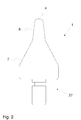
- FIG. 1 An embodiment of a spinning tip 1 according to the invention, which in turn is connected in operation with a spindle body 2 (comparable to the construction according to FIG. 1 ), show the Figures 2 and 3 ,
- the attachment 8 is configured cap-shaped in the example shown and surrounds a corresponding frontal extension 9 of the base body 7.
- the attachment 8 can be made particularly thin-walled, since it is supported in the direction of the Garnabzugskanals 6 of said extension 9.
- the connection between attachment 8 and main body 7 takes place, for example, by gluing or else corresponding form-locking connection mechanisms (screws, clips, etc.).
- the advantage of the structure according to the invention lies in the fact that the attachment 8 has relatively small dimensions compared to the base body 7. It can therefore be made of an (artificial) gemstone (alternatively made of ceramic or a particularly abrasion-resistant metal or Plastic) are manufactured without the production cost of the entire spinning tip 1 increase excessively.
- the spinning tip 1 thus receives in the most mechanically stressed area around the inlet opening 4 a kind of wear protection, so that in particular the responsible for the yarn quality inlet contour around the inlet opening 4 remains constant for a long time.
- the transition between the body 7 and attachment 8 is preferably carried out continuously. This is made possible for example by a recess 10 of the base body 7, which substantially corresponds to the volume of the attachment 8.
- a further embodiment of the spinning tip 1 according to the invention shows FIG. 4 , in which the attachment 8 is glued only from above on the end face of the main body 7.
- the outer contours of the attachment 8 are rounded in order to avoid damaging the yarn 5.
- the main body 7 can also be made in all variants of a relatively inexpensive material, such as a metal or plastic, since the wear in the area adjacent to the attachment 8 area is relatively low.
- the attachment 8 has - in the example shown four - evenly distributed notches 11 in the circumferential direction of the cap-shaped attachment 8. These extend from the inlet opening 4 facing away from the end face in the direction of the inlet opening 4 and finally open in respect to the Garnabzugskanals 6 radial direction in a recess 13 which extends between the part of the Garnabzugskanals 6 extending through the cap 8, and the part of Garnabzugskanals 6, which extends through the base body 7, is arranged.
- the depression 13 is also delimited on the front side by a step 14, which results from the different inner diameter of the depression 13 and the yarn withdrawal channel 6 of the attachment 8.
- notches 11 delimiting foot portions 31 of the attachment 8 on the side facing away from the inlet opening 4 edge portions 12 having a stepped inner contour 28 which are supported on a likewise stepped outer contour 30 of the base body 7.
Landscapes
- Engineering & Computer Science (AREA)
- Mechanical Engineering (AREA)
- Textile Engineering (AREA)
- Spinning Or Twisting Of Yarns (AREA)
Applications Claiming Priority (1)
| Application Number | Priority Date | Filing Date | Title |
|---|---|---|---|
| DE201110053837 DE102011053837A1 (de) | 2011-09-21 | 2011-09-21 | Spinnspitze für eine Hohlspindel einer Luftspinnmaschine |
Publications (2)
| Publication Number | Publication Date |
|---|---|
| EP2573218A2 true EP2573218A2 (fr) | 2013-03-27 |
| EP2573218A3 EP2573218A3 (fr) | 2015-03-25 |
Family
ID=46939597
Family Applications (1)
| Application Number | Title | Priority Date | Filing Date |
|---|---|---|---|
| EP12184602.6A Withdrawn EP2573218A3 (fr) | 2011-09-21 | 2012-09-17 | Pointe de filature pour arbre creux d'un métier à tisser |
Country Status (3)
| Country | Link |
|---|---|
| EP (1) | EP2573218A3 (fr) |
| CN (1) | CN103014943A (fr) |
| DE (1) | DE102011053837A1 (fr) |
Cited By (4)
| Publication number | Priority date | Publication date | Assignee | Title |
|---|---|---|---|---|
| EP2677070A1 (fr) * | 2012-06-22 | 2013-12-25 | Murata Machinery, Ltd. | Corps d'arbre de guidage creux, fileuse à air et machine de renvideur de fil comprenant celle-ci |
| EP3012362A3 (fr) * | 2014-09-30 | 2016-07-27 | Murata Machinery, Ltd. | Tige de guidage creuse, dispositif de filières à air et machinerie textile |
| EP3744880A1 (fr) * | 2019-05-29 | 2020-12-02 | Maschinenfabrik Rieter AG | Élément tournant pour une filière d'une machine à filer à jet d'air ainsi que filière |
| EP4043625A1 (fr) | 2021-02-10 | 2022-08-17 | Saurer Intelligent Technology AG | Élément de filature |
Families Citing this family (3)
| Publication number | Priority date | Publication date | Assignee | Title |
|---|---|---|---|---|
| CH708164A1 (de) * | 2013-06-14 | 2014-12-15 | Rieter Ag Maschf | Spinndüse sowie damit ausgerüstete Spinnstelle einer Luftspinnmaschine. |
| CN103305979B (zh) * | 2013-06-24 | 2015-12-23 | 东华大学 | 一种喷气涡流纺沟槽型低落纤空心锭 |
| DE102016116693A1 (de) * | 2016-09-07 | 2018-03-08 | Maschinenfabrik Rieter Ag | Garnbildungselement und Spinndüse für eine Luftspinnmaschine |
Citations (1)
| Publication number | Priority date | Publication date | Assignee | Title |
|---|---|---|---|---|
| DE102004044345A1 (de) | 2004-09-09 | 2006-03-16 | Wilhelm Stahlecker Gmbh | Luftdüsenspinnvorrichtung |
Family Cites Families (10)
| Publication number | Priority date | Publication date | Assignee | Title |
|---|---|---|---|---|
| DE3927910A1 (de) * | 1989-08-24 | 1991-02-28 | Stahlecker Fritz | Falschdrallduese fuer pneumatisches falschdrallspinnen |
| CH679587A5 (fr) * | 1989-08-25 | 1992-03-13 | Rieter Ag Maschf | |
| JPH07126923A (ja) * | 1993-11-04 | 1995-05-16 | Koyo Seiko Co Ltd | 紡機用スピンドル装置 |
| JP3094364B2 (ja) * | 1997-05-13 | 2000-10-03 | 村田機械株式会社 | 空気精紡機のスピンドル部材 |
| DE10333411A1 (de) * | 2003-07-15 | 2005-02-03 | Wilhelm Stahlecker Gmbh | Vorrichtung zum Herstellen eines gesponnenen Fadens aus einem Stapelfaserverband |
| DE10349651A1 (de) * | 2003-10-20 | 2005-05-19 | Wilhelm Stahlecker Gmbh | Luftdüsen-Spinnvorrichtung |
| DE10358484A1 (de) * | 2003-12-11 | 2005-07-07 | Wilhelm Stahlecker Gmbh | Vorrichtung zum Herstellen eines gesponnenen Fadens aus einem Stapelfaserverband |
| JP2008510891A (ja) * | 2004-08-20 | 2008-04-10 | マシーネンファブリク リーター アクチェンゲゼルシャフト | インジェクター通路を備えたスピンドル、及びエアジェット式紡糸機の糸つぎのための方法 |
| DE102006018249A1 (de) * | 2006-04-13 | 2007-10-18 | Wilhelm Stahlecker Gmbh | Spindelförmiges Bauteil für eine Luftdüsenspinnvorrichtung mit einem Injektionskanal |
| US8464510B2 (en) * | 2009-07-16 | 2013-06-18 | Maschinenfabrik Rieter Ag | Air-jet spinning apparatus |
-
2011
- 2011-09-21 DE DE201110053837 patent/DE102011053837A1/de not_active Withdrawn
-
2012
- 2012-09-17 EP EP12184602.6A patent/EP2573218A3/fr not_active Withdrawn
- 2012-09-21 CN CN2012103540943A patent/CN103014943A/zh active Pending
Patent Citations (1)
| Publication number | Priority date | Publication date | Assignee | Title |
|---|---|---|---|---|
| DE102004044345A1 (de) | 2004-09-09 | 2006-03-16 | Wilhelm Stahlecker Gmbh | Luftdüsenspinnvorrichtung |
Cited By (6)
| Publication number | Priority date | Publication date | Assignee | Title |
|---|---|---|---|---|
| EP2677070A1 (fr) * | 2012-06-22 | 2013-12-25 | Murata Machinery, Ltd. | Corps d'arbre de guidage creux, fileuse à air et machine de renvideur de fil comprenant celle-ci |
| JP2014005562A (ja) * | 2012-06-22 | 2014-01-16 | Murata Mach Ltd | 中空ガイド軸体、空気紡績装置、及びこれを備える糸巻取機 |
| EP3012362A3 (fr) * | 2014-09-30 | 2016-07-27 | Murata Machinery, Ltd. | Tige de guidage creuse, dispositif de filières à air et machinerie textile |
| EP3156526A1 (fr) * | 2014-09-30 | 2017-04-19 | Murata Machinery, Ltd. | Tige de guidage creuse, dispositif de filières à air et machinerie textile |
| EP3744880A1 (fr) * | 2019-05-29 | 2020-12-02 | Maschinenfabrik Rieter AG | Élément tournant pour une filière d'une machine à filer à jet d'air ainsi que filière |
| EP4043625A1 (fr) | 2021-02-10 | 2022-08-17 | Saurer Intelligent Technology AG | Élément de filature |
Also Published As
| Publication number | Publication date |
|---|---|
| DE102011053837A1 (de) | 2013-03-21 |
| EP2573218A3 (fr) | 2015-03-25 |
| CN103014943A (zh) | 2013-04-03 |
Similar Documents
| Publication | Publication Date | Title |
|---|---|---|
| EP1845180B1 (fr) | Composant en forme de broche pour dispositif de filage à jet d'air doté d'un canal d'injection | |
| DE102011053837A1 (de) | Spinnspitze für eine Hohlspindel einer Luftspinnmaschine | |
| EP2329066B1 (fr) | Groupe de filature a buse d'air comprenant un composant en forme de broche | |
| EP0990719B1 (fr) | Métier à filer | |
| DE102009034206A1 (de) | Bauteil für eine Luftdüsenspinnvorrichtung | |
| EP2730685B1 (fr) | Elément de formation de fil pour métier à tisser à jet d'air comprenant un insert et filière équipée de celui-ci | |
| EP1786961A1 (fr) | Dispositif de filature a jet d'air | |
| EP1748094B1 (fr) | Métiers à filer pour la fabrication de fil en utilisant des jets d'air vortex | |
| EP1288354A2 (fr) | Mesures pour influencer le flux d'air dans un canal de filature d'un métier à filer a vortex | |
| EP1335050B1 (fr) | Machine textile comprennant un canal pour alimenter des fibres et une surface pour guider des fibres | |
| EP2454403B1 (fr) | Machine à filer à jet d'air | |
| EP2573219A2 (fr) | Élément de formation de fil pour un poste de filage d'un métier à tisser à jet d'air et procédé de préparation d'un procédé de filage sur un métier à tisser à jet d'air | |
| CH674855A5 (fr) | ||
| DE19926492A1 (de) | Spinnvorrichtung | |
| EP3293294B1 (fr) | Élément de formation de fil et buse de filage pour un métier à filer à jet d'air | |
| AT501520B1 (de) | Garnabzugseinrichtung für offenend-spinnvorrichtungen | |
| EP4043625B1 (fr) | Élément de filature | |
| DE10393063B4 (de) | Fadenabzugsdüse | |
| DE19733614A1 (de) | Absaugeinrichtung am Streckwerk einer Spinnmaschine | |
| EP2886688B1 (fr) | Empiècement et métier à filer | |
| EP1217111A2 (fr) | Dispositif de filage pneumatic | |
| DE19846770A1 (de) | Rotor für Offenend-Spinnmaschinen | |
| EP1802791A1 (fr) | Dispositif de filage a buses d'air | |
| WO2004059052A1 (fr) | Boitier de filieres destine a un dispositif de filieres a air | |
| DE19819850C2 (de) | Spinnflügel für eine Vorspinnmaschine |
Legal Events
| Date | Code | Title | Description |
|---|---|---|---|
| PUAI | Public reference made under article 153(3) epc to a published international application that has entered the european phase |
Free format text: ORIGINAL CODE: 0009012 |
|
| AK | Designated contracting states |
Kind code of ref document: A2 Designated state(s): AL AT BE BG CH CY CZ DE DK EE ES FI FR GB GR HR HU IE IS IT LI LT LU LV MC MK MT NL NO PL PT RO RS SE SI SK SM TR |
|
| AX | Request for extension of the european patent |
Extension state: BA ME |
|
| PUAL | Search report despatched |
Free format text: ORIGINAL CODE: 0009013 |
|
| AK | Designated contracting states |
Kind code of ref document: A3 Designated state(s): AL AT BE BG CH CY CZ DE DK EE ES FI FR GB GR HR HU IE IS IT LI LT LU LV MC MK MT NL NO PL PT RO RS SE SI SK SM TR |
|
| AX | Request for extension of the european patent |
Extension state: BA ME |
|
| RIC1 | Information provided on ipc code assigned before grant |
Ipc: D01H 1/115 20060101AFI20150213BHEP |
|
| STAA | Information on the status of an ep patent application or granted ep patent |
Free format text: STATUS: THE APPLICATION IS DEEMED TO BE WITHDRAWN |
|
| 18D | Application deemed to be withdrawn |
Effective date: 20150926 |