EP3744880A1 - Élément tournant pour une filière d'une machine à filer à jet d'air ainsi que filière - Google Patents
Élément tournant pour une filière d'une machine à filer à jet d'air ainsi que filière Download PDFInfo
- Publication number
- EP3744880A1 EP3744880A1 EP20174001.6A EP20174001A EP3744880A1 EP 3744880 A1 EP3744880 A1 EP 3744880A1 EP 20174001 A EP20174001 A EP 20174001A EP 3744880 A1 EP3744880 A1 EP 3744880A1
- Authority
- EP
- European Patent Office
- Prior art keywords
- swirl
- spinneret
- swirl element
- air nozzles
- air
- Prior art date
- Legal status (The legal status is an assumption and is not a legal conclusion. Google has not performed a legal analysis and makes no representation as to the accuracy of the status listed.)
- Withdrawn
Links
Images


Classifications
-
- D—TEXTILES; PAPER
- D01—NATURAL OR MAN-MADE THREADS OR FIBRES; SPINNING
- D01H—SPINNING OR TWISTING
- D01H1/00—Spinning or twisting machines in which the product is wound-up continuously
- D01H1/11—Spinning by false-twisting
- D01H1/115—Spinning by false-twisting using pneumatic means
-
- D—TEXTILES; PAPER
- D01—NATURAL OR MAN-MADE THREADS OR FIBRES; SPINNING
- D01H—SPINNING OR TWISTING
- D01H4/00—Open-end spinning machines or arrangements for imparting twist to independently moving fibres separated from slivers; Piecing arrangements therefor; Covering endless core threads with fibres by open-end spinning techniques
- D01H4/02—Open-end spinning machines or arrangements for imparting twist to independently moving fibres separated from slivers; Piecing arrangements therefor; Covering endless core threads with fibres by open-end spinning techniques imparting twist by a fluid, e.g. air vortex
Definitions
- the present invention relates to a swirl element for a spinneret of an air-jet spinning machine, the swirl element comprising an inlet for a fiber structure, the swirl element comprising air nozzles each with an outlet opening, which serve to introduce air into a swirl chamber of the spinneret when the swirl element is used as intended to produce a yarn within the swirl chamber from the fiber structure entering via the inlet in a transport direction.
- a spinneret for an air-jet spinning machine having an inlet for a fiber structure and an internal vortex chamber, the spinneret having a yarn forming element extending at least partially into the vortex chamber with an inlet opening for the fibers of the fiber structure, the spinneret having air nozzles each comprises an outlet opening via which air can be introduced into the swirl chamber in order to give the fiber structure a rotation to produce a yarn in the area of the yarn forming element, and wherein the spinneret has an outlet via which the yarn can be withdrawn from the swirl chamber.
- Corresponding spinnerets are used to produce a yarn from an elongated fiber structure with the aid of a vortex air flow generated by air nozzles within a vortex chamber of the spinneret.
- the fiber structure is supplied by a drafting system, which evens out the fiber structure before it enters the spinneret.
- the inlet of the spinneret is formed or limited by a so-called swirl element that guides the into the Spinneret entering fibers of the fiber composite is used and which includes the outlet openings of the air nozzles.
- the outer fibers of the fiber structure After entering the spinneret, the outer fibers of the fiber structure are wound around the inner fibers (core fibers) in the area of the inlet opening of a usually spindle-shaped yarn-forming element, which is placed in the swirl chamber, so that the result is a yarn which is finally produced via a take-off channel of the yarn-forming element can be withdrawn from the swirl chamber and thus from the spinneret and wound onto a sleeve with the aid of a winding device.
- the object of the present invention is therefore to propose a swirl element and a spinning nozzle for an air-jet spinning machine, which develop the state of the art.
- the swirl element according to the invention is used in a spinneret of an air-jet spinning machine, the swirl element comprising an inlet for a fiber structure, and the swirl element comprising air nozzles (preferably in the form of bores within a wall of the swirl element), each with an outlet opening, which are used in the Intended use of the swirl element (ie after installation in a spinneret) to introduce air into a swirl chamber of the spinneret in order to produce a yarn within the swirl chamber from the fiber structure entering via the inlet in a transport direction.
- the swirl element comprises a section made of a ceramic material.
- the swirl element thus also comprises one or more further sections that do not consist of a ceramic material. Furthermore, it is provided that the said section is arranged on a side of the outlet openings of the air nozzles that is remote from the inlet, with respect to the transport direction.
- the air nozzles are located in a region of the swirl element which is arranged in front of the section made of ceramic material in relation to the transport direction.
- the air nozzles are located in particular in a region of the swirl element which is made of metal or plastic and can therefore be introduced into the swirl element in a conventional manner by drilling.
- the distance between the outlet openings of the air nozzles and the section mentioned is between 0.05 mm and 5 mm, preferably between 0.05 mm and 0.5 mm.
- the area in which the air nozzles are arranged, or in which the outlet openings of the air nozzles are located are arranged in a section of the swirl element that does not consist of a ceramic material.
- the transition between the ceramic material and the non-ceramic material should therefore be between the outlet openings of the air nozzles and the inlet opening of the yarn forming element when the swirl element is installed in a spinneret of an air-jet spinning machine, seen in the transport direction.
- the section is formed by an insert which is connected to a base body of the swirl element, the base body including the outlet openings of the air nozzles.
- the entire insert is preferably made from a ceramic material.
- the connection between the insert and the base body takes place, for example, by means of a form fit or by a material connection, for example with the aid of an adhesive.
- the insert is preferably at least in a direction perpendicular to the mentioned transport direction surrounded in sections by the base body.
- the section made of a ceramic material is formed entirely from the said insert.
- the base body consists at least for the most part of a non-ceramic material, preferably of a metal.
- the base body should consist entirely or partially of a steel, preferably a hardened steel. It is also conceivable that the base body consists entirely or partially of a plastic.
- the air nozzles are preferably exclusively in the base body, i. not arranged in the portion made of a ceramic material.
- the base body and the insert jointly form a passage for the fibers of the fiber composite.
- both the base body and the insert have a passage opening which together form the passage channel.
- the outlet openings of the air nozzles are arranged in the region of a preferably cylindrical inner surface of the base body.
- the air nozzles are preferably arranged obliquely to a longitudinal axis of the base body and, as soon as they come with Compressed air is applied, a vortex air flow in the free space surrounded by the inner surface of the base body.
- the air nozzles preferably penetrate the entire outer wall of the base body. If the swirl element is installed in a spinneret, the compressed air that is necessary for the said vortex air flow can be introduced into the swirl chamber from outside the swirl element through the base body.
- the inner surface of the base body viewed in the direction of transport of the fiber composite, merges flush into an inner surface of the insert. This creates a smooth transition so that an undesired deflection of the fibers entering the swirl element is avoided.
- the inner surface of the base body and the inner surface of the insert together form the above-mentioned passage channel for the fibers of the fiber composite.
- the base body has an annular step into which the insert is inserted in order to enable the flush transition between the base body and the insert.
- the annular gradation is preferably located in the area of a contact surface between the base body and the insert.
- a cross-sectional widening of the base body, in particular a step-shaped, cross-sectional widening in the transport direction is therefore preferably provided, which is used to accommodate the insert.
- the insert is designed as a sleeve.
- the sleeve has a wall which delimits a passage opening of the sleeve towards the outside, the passage opening serving for the passage of fibers. It is advantageous if the inside diameter of the sleeve widens in sections, viewed from a side facing the air nozzles in the transport direction of the fiber strand.
- the yarn-forming element which comprises the inlet opening for the fibers or for the yarn made from the fibers.
- the sleeve is designed to be rotationally symmetrical about an axis of rotation. This enables a simple connection between the sleeve and the base body, since the sleeve is inevitably used in the correct angular position with respect to the base body.
- the axis of rotation preferably runs in the intended transport direction of the fibers through the twist element.
- the length of the sleeve extending along the axis of rotation is between 1 mm and 5 mm, preferably between 1.5 mm and 4 mm. Said longitudinal extension is sufficient to provide the area of the swirl element with a section made of a ceramic material which, when the swirl element is in operation, comes into contact with the fibers of the above-mentioned fiber sun in a spinneret.
- the remaining area of the swirl element can consist of a non-ceramic material.
- the sleeve has a wall thickness whose amount is between 0.1 mm and 4 mm, preferably between 0.1 mm and 2 mm, at least in sections.
- the swirl element is preferably fastened in a spinneret not via the sleeve, but via the base element.
- the invention also relates to a spinneret for an air-jet spinning machine.
- the spinneret comprises an inlet for a fiber structure and an internal swirl chamber. Furthermore, the spinneret has a spindle-shaped yarn-forming element that extends at least partially into the swirl chamber and has an inlet opening for the fibers of the fiber composite and a take-off channel for the Yarn produced in the spinneret.
- the spinneret also has several air nozzles, each with an outlet opening through which air can be introduced into the vortex chamber. Finally, there is an outlet which forms the end of the aforementioned withdrawal channel and via which the yarn can be withdrawn from the swirl chamber.
- the spinneret is now characterized in that it comprises a section made of a ceramic material, the section being placed between the outlet openings of the air nozzles and the outlet of the spinneret and surrounding the inlet opening of the yarn forming element and, when the spinneret is in operation, with the fibers of the fiber strand in Contact reached.
- the fiber ends spread out to the side, resulting in the aforementioned fiber sun. The fiber ends are guided past the section mentioned.
- the section consists of a ceramic material, it has a very high wear resistance compared to the fiber ends, so that the service life of the spinneret according to the invention is much longer than the service life of known spinnerets in which the section in the area of the inlet opening is made of a metal.
- the spinneret comprises a swirl element according to the previous or following description, the swirl element comprising the inlet for the fiber structure, the outlet openings of the air nozzles and the section made of a ceramic material.
- the swirl element can have the features described so far or below, individually or in any combination.
- the swirl element comprises a base body and an insert having the section mentioned, it is advantageous if the swirl element is connected to a wall of the spinneret via the base body.
- Figure 1 shows a longitudinal section of a spinning nozzle 1 according to the invention for an air-jet spinning machine. If the spinning nozzle 1 is integrated in an air-jet spinning machine, a strand-like fiber structure 3 is fed to the spinning nozzle 1 in a predetermined transport direction T.
- the fiber structure 3 is usually delivered to the area of the inlet 2 of the spinneret 1, which is formed by a so-called swirl element 20, with the aid of a drafting device (not shown), and there it reaches the interior of the spinneret 1.
- the inlet 2 can pass through a separate fiber guide element 15 may be partially limited.
- a vortex chamber 4 i. a cavity into which a spindle-shaped yarn forming element 5 protrudes.
- air nozzles 7 are present, via which compressed air can be introduced into the swirl chamber 4 in the form of a vortex air flow when the spinneret 1 is in operation.
- the outlet openings 8 of the air nozzles 7 are preferably located in front of the inlet opening 6 of the yarn forming element, as seen in the transport direction T.
- the swirl element 20 is made of a metal, so that the inwardly facing surface of the swirl element 20 is worn due to the mechanical contact between the fiber ends of the fiber sun 22 and the area of the swirl element 20 surrounding the fiber sun 22.
- the spinneret 1 or the swirl element 20 have a section 11 which comes into contact with the fiber ends of the fiber sun 22 during operation of the spinneret 1, this section 11 being made of a ceramic material is.
- a ceramic material is also understood within the scope of the invention to be an inorganic, non-metallic and fired material (such as porcelain, for example).
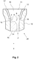
- the said section 11 is formed by an insert 12 which is connected to a base body 13, the insert 12 being arranged after the outlet openings 8 of the air nozzles 7, as seen in the transport direction T.
- the air nozzles 7 can be placed in an area that is not made of a ceramic material but, for example, of metal or plastic. In this case, the air nozzles 7 can be produced relatively easily by drilling.
- the insert 12 is preferably designed to be rotationally symmetrical with respect to a longitudinal axis of the swirl element 20, which runs in the aforementioned transport direction T.
- the insert 12 is in the form of a sleeve 17.
- the base body 13 as in FIG Figure 1 shown, has an annular step 19 which forms a space for receiving the insert 12.
- Figure 3 shows the same view as Figure 2 , where instead of the in Figure 2 A few relevant dimensions of the swirl element 20 are identified by reference numerals shown.
- the swirl element 20 can also include the fiber guide element 15 as a separate component. It is also conceivable that a corresponding fiber guide element 15 is dispensed with if the base body 13 alone delimits the inlet opening 6.
- the section 11 made of a ceramic material, in particular the insert 12 is as close as possible to the outlet openings 8 of the air nozzles 7, viewed in the transport direction T. This ensures that the area in which the fiber sun 22 can form consists of the ceramic material.
- the distance A between the outlet openings 8 of the air nozzles 7 and the aforementioned section 11 is therefore preferably only 0.05 mm to 5 mm in the transport direction T.
- the wall thickness W of the insert 12 can be relatively small if the entire insert 12 is made of the ceramic material.
- the wall thickness W of the insert 12 or the sleeve 17 forming the insert 12, at least in sections, has an amount that is between 0.1 mm and 4 mm, preferably between 0.1 mm and 2 mm.
- the longitudinal extent L of the insert 12 or the sleeve 17 forming the insert 12, which extends in the longitudinal axis of the swirl element 20, preferably has an amount between 1 mm and 5 mm, preferably between 1.5 mm and 4 mm, the longitudinal extent increasing L extends in said transport direction T.
- the insert 12 has an axis of rotation R which runs parallel to or congruent with the transport direction T.
Landscapes
- Engineering & Computer Science (AREA)
- Mechanical Engineering (AREA)
- Textile Engineering (AREA)
- Spinning Or Twisting Of Yarns (AREA)
- Spinning Methods And Devices For Manufacturing Artificial Fibers (AREA)
Applications Claiming Priority (1)
| Application Number | Priority Date | Filing Date | Title |
|---|---|---|---|
| DE102019114500.7A DE102019114500A1 (de) | 2019-05-29 | 2019-05-29 | Drallelement für eine Spinndüse einer Luftspinnmaschine sowie Spinndüse |
Publications (1)
| Publication Number | Publication Date |
|---|---|
| EP3744880A1 true EP3744880A1 (fr) | 2020-12-02 |
Family
ID=70681717
Family Applications (1)
| Application Number | Title | Priority Date | Filing Date |
|---|---|---|---|
| EP20174001.6A Withdrawn EP3744880A1 (fr) | 2019-05-29 | 2020-05-12 | Élément tournant pour une filière d'une machine à filer à jet d'air ainsi que filière |
Country Status (3)
| Country | Link |
|---|---|
| EP (1) | EP3744880A1 (fr) |
| CN (1) | CN112011858B (fr) |
| DE (1) | DE102019114500A1 (fr) |
Citations (6)
| Publication number | Priority date | Publication date | Assignee | Title |
|---|---|---|---|---|
| DE3829150A1 (de) * | 1988-08-27 | 1990-03-01 | Fritz Stahlecker | Luftduese fuer pneumatisches falschdrallspinnen |
| DE10261778A1 (de) * | 2002-12-20 | 2004-07-01 | Wilhelm Stahlecker Gmbh | Spinndüsengehäuse für eine Luftdüsenspinnvorrichtung |
| EP2573218A2 (fr) * | 2011-09-21 | 2013-03-27 | Maschinenfabrik Rieter AG | Pointe de filature pour arbre creux d'un métier à tisser |
| CN105239223A (zh) * | 2015-10-22 | 2016-01-13 | 陕西华燕航空仪表有限公司 | 一种喷气涡流纺纱器 |
| EP3115485A1 (fr) | 2015-07-06 | 2017-01-11 | Murata Machinery, Ltd. | Bloc de buses, fileuse pneumatique et fileuse |
| CH713500A2 (de) * | 2017-02-28 | 2018-08-31 | Rieter Ag Maschf | Luftspinndüse für eine Luftspinnmaschine zur Herstellung eines Garns aus einem strangförmigen Faserverband. |
Family Cites Families (4)
| Publication number | Priority date | Publication date | Assignee | Title |
|---|---|---|---|---|
| DE4007517A1 (de) * | 1990-03-09 | 1991-09-12 | Schubert & Salzer Maschinen | Offenendspinnvorrichtung |
| JP2510792B2 (ja) * | 1991-02-27 | 1996-06-26 | 京セラ株式会社 | 紡糸口金 |
| DE10222635A1 (de) * | 2002-05-17 | 2003-12-18 | Ilias Efthimiou | Fadenabzugsdüse |
| WO2006063482A1 (fr) * | 2004-12-15 | 2006-06-22 | Maschinenfabrik Rieter Ag | Boite a filer a broche interchangeable |
-
2019
- 2019-05-29 DE DE102019114500.7A patent/DE102019114500A1/de active Pending
-
2020
- 2020-05-12 EP EP20174001.6A patent/EP3744880A1/fr not_active Withdrawn
- 2020-05-27 CN CN202010463539.6A patent/CN112011858B/zh active Active
Patent Citations (6)
| Publication number | Priority date | Publication date | Assignee | Title |
|---|---|---|---|---|
| DE3829150A1 (de) * | 1988-08-27 | 1990-03-01 | Fritz Stahlecker | Luftduese fuer pneumatisches falschdrallspinnen |
| DE10261778A1 (de) * | 2002-12-20 | 2004-07-01 | Wilhelm Stahlecker Gmbh | Spinndüsengehäuse für eine Luftdüsenspinnvorrichtung |
| EP2573218A2 (fr) * | 2011-09-21 | 2013-03-27 | Maschinenfabrik Rieter AG | Pointe de filature pour arbre creux d'un métier à tisser |
| EP3115485A1 (fr) | 2015-07-06 | 2017-01-11 | Murata Machinery, Ltd. | Bloc de buses, fileuse pneumatique et fileuse |
| CN105239223A (zh) * | 2015-10-22 | 2016-01-13 | 陕西华燕航空仪表有限公司 | 一种喷气涡流纺纱器 |
| CH713500A2 (de) * | 2017-02-28 | 2018-08-31 | Rieter Ag Maschf | Luftspinndüse für eine Luftspinnmaschine zur Herstellung eines Garns aus einem strangförmigen Faserverband. |
Also Published As
| Publication number | Publication date |
|---|---|
| CN112011858A (zh) | 2020-12-01 |
| DE102019114500A1 (de) | 2020-12-03 |
| CN112011858B (zh) | 2023-12-08 |
Similar Documents
| Publication | Publication Date | Title |
|---|---|---|
| EP2895647B1 (fr) | Poste de filage d'un banc à broches | |
| EP2511403B1 (fr) | Banc à broches pour la fabrication d'une mèche | |
| EP1845180B1 (fr) | Composant en forme de broche pour dispositif de filage à jet d'air doté d'un canal d'injection | |
| EP2730685B1 (fr) | Elément de formation de fil pour métier à tisser à jet d'air comprenant un insert et filière équipée de celui-ci | |
| EP3309281B1 (fr) | Élément de guidage fibres pour jet de filature d'un métier à tisser à jet d'air et procédé de fonctionnement d'un métier à tisser à jet d'air | |
| EP2927355A2 (fr) | Poste de filage d'un métier à filer à jet d'air et embout pour la fixation sur une filière d'un métier à filer à jet d'air | |
| EP3449048A1 (fr) | Métier à filer à jet d'air et procédé de production d'un fil | |
| EP3155151B1 (fr) | Buse de filage pour un métier à filer à jet d'air et métier à filer à jet d'air avec buse de filage correspondante | |
| EP2573218A2 (fr) | Pointe de filature pour arbre creux d'un métier à tisser | |
| EP2813604B1 (fr) | Filière et poste de filage d'un métier à filer à jet d'air en étant équipé | |
| EP2573219A2 (fr) | Élément de formation de fil pour un poste de filage d'un métier à tisser à jet d'air et procédé de préparation d'un procédé de filage sur un métier à tisser à jet d'air | |
| EP3293294B1 (fr) | Élément de formation de fil et buse de filage pour un métier à filer à jet d'air | |
| WO2018087054A1 (fr) | Filière pour machine à filer à jet d'air et procédé de fonctionnement de celle-ci | |
| EP3744880A1 (fr) | Élément tournant pour une filière d'une machine à filer à jet d'air ainsi que filière | |
| AT501520B1 (de) | Garnabzugseinrichtung für offenend-spinnvorrichtungen | |
| EP3680373B1 (fr) | Élément de guidage de fibre pour une buse de filage ainsi que buse de filage équipée d'un tel élément de guidage de fibre | |
| EP4043625B1 (fr) | Élément de filature | |
| WO2005061765A1 (fr) | Dispositif pour filer un fil a partir d'une meche de fibres discontinues | |
| EP3464691A1 (fr) | Élément de formation de fil pour banc à broches et banc à broches équipé de ce dernier | |
| EP1563130B1 (fr) | Dispositif de filage a buse d'air | |
| EP3889327B1 (fr) | Poste de travail d'un métier à filer à jet d'air | |
| EP2578730A2 (fr) | Élément de formation de fil pour un poste de filage d'un métier à tisser à jet d'air avec un élément anti-torsion du fil | |
| EP3997263B1 (fr) | Procédé de rattache pour une buse de filage d'un métier à filer à jet d'air, et métier à filer à jet d'air | |
| DE4021695A1 (de) | Fadenanlegeeinrichtung | |
| DE19819850A1 (de) | Spinnflügel für eine Vorspinnmaschine |
Legal Events
| Date | Code | Title | Description |
|---|---|---|---|
| PUAI | Public reference made under article 153(3) epc to a published international application that has entered the european phase |
Free format text: ORIGINAL CODE: 0009012 |
|
| STAA | Information on the status of an ep patent application or granted ep patent |
Free format text: STATUS: THE APPLICATION HAS BEEN PUBLISHED |
|
| AK | Designated contracting states |
Kind code of ref document: A1 Designated state(s): AL AT BE BG CH CY CZ DE DK EE ES FI FR GB GR HR HU IE IS IT LI LT LU LV MC MK MT NL NO PL PT RO RS SE SI SK SM TR |
|
| AX | Request for extension of the european patent |
Extension state: BA ME |
|
| STAA | Information on the status of an ep patent application or granted ep patent |
Free format text: STATUS: REQUEST FOR EXAMINATION WAS MADE |
|
| 17P | Request for examination filed |
Effective date: 20210601 |
|
| RBV | Designated contracting states (corrected) |
Designated state(s): AL AT BE BG CH CY CZ DE DK EE ES FI FR GB GR HR HU IE IS IT LI LT LU LV MC MK MT NL NO PL PT RO RS SE SI SK SM TR |
|
| STAA | Information on the status of an ep patent application or granted ep patent |
Free format text: STATUS: EXAMINATION IS IN PROGRESS |
|
| 17Q | First examination report despatched |
Effective date: 20220829 |
|
| STAA | Information on the status of an ep patent application or granted ep patent |
Free format text: STATUS: THE APPLICATION HAS BEEN WITHDRAWN |
|
| 18W | Application withdrawn |
Effective date: 20221121 |