EP2573280A2 - Structure en acier supportant la superstructure d'un engin de travail - Google Patents
Structure en acier supportant la superstructure d'un engin de travail Download PDFInfo
- Publication number
- EP2573280A2 EP2573280A2 EP12008385A EP12008385A EP2573280A2 EP 2573280 A2 EP2573280 A2 EP 2573280A2 EP 12008385 A EP12008385 A EP 12008385A EP 12008385 A EP12008385 A EP 12008385A EP 2573280 A2 EP2573280 A2 EP 2573280A2
- Authority
- EP
- European Patent Office
- Prior art keywords
- advantageously
- screw
- bolt
- implement according
- movable
- Prior art date
- Legal status (The legal status is an assumption and is not a legal conclusion. Google has not performed a legal analysis and makes no representation as to the accuracy of the status listed.)
- Withdrawn
Links
- 229910000831 Steel Inorganic materials 0.000 title claims abstract description 30
- 239000010959 steel Substances 0.000 title claims abstract description 30
- 238000010276 construction Methods 0.000 claims description 26
- 238000003825 pressing Methods 0.000 claims description 5
- 238000004519 manufacturing process Methods 0.000 description 4
- 230000005484 gravity Effects 0.000 description 3
- 230000003068 static effect Effects 0.000 description 3
- 230000001133 acceleration Effects 0.000 description 2
- 238000005452 bending Methods 0.000 description 2
- 210000004907 gland Anatomy 0.000 description 2
- 230000006835 compression Effects 0.000 description 1
- 238000007906 compression Methods 0.000 description 1
- 230000000694 effects Effects 0.000 description 1
- 239000002828 fuel tank Substances 0.000 description 1
- 239000000463 material Substances 0.000 description 1
- 238000000034 method Methods 0.000 description 1
Images





Classifications
-
- E—FIXED CONSTRUCTIONS
- E02—HYDRAULIC ENGINEERING; FOUNDATIONS; SOIL SHIFTING
- E02F—DREDGING; SOIL-SHIFTING
- E02F9/00—Component parts of dredgers or soil-shifting machines, not restricted to one of the kinds covered by groups E02F3/00 - E02F7/00
- E02F9/08—Superstructures; Supports for superstructures
- E02F9/0808—Improving mounting or assembling, e.g. frame elements, disposition of all the components on the superstructures
-
- E—FIXED CONSTRUCTIONS
- E02—HYDRAULIC ENGINEERING; FOUNDATIONS; SOIL SHIFTING
- E02F—DREDGING; SOIL-SHIFTING
- E02F9/00—Component parts of dredgers or soil-shifting machines, not restricted to one of the kinds covered by groups E02F3/00 - E02F7/00
- E02F9/006—Pivot joint assemblies
-
- Y—GENERAL TAGGING OF NEW TECHNOLOGICAL DEVELOPMENTS; GENERAL TAGGING OF CROSS-SECTIONAL TECHNOLOGIES SPANNING OVER SEVERAL SECTIONS OF THE IPC; TECHNICAL SUBJECTS COVERED BY FORMER USPC CROSS-REFERENCE ART COLLECTIONS [XRACs] AND DIGESTS
- Y10—TECHNICAL SUBJECTS COVERED BY FORMER USPC
- Y10T—TECHNICAL SUBJECTS COVERED BY FORMER US CLASSIFICATION
- Y10T403/00—Joints and connections
- Y10T403/32—Articulated members
- Y10T403/32606—Pivoted
- Y10T403/32861—T-pivot, e.g., wrist pin, etc.
-
- Y—GENERAL TAGGING OF NEW TECHNOLOGICAL DEVELOPMENTS; GENERAL TAGGING OF CROSS-SECTIONAL TECHNOLOGIES SPANNING OVER SEVERAL SECTIONS OF THE IPC; TECHNICAL SUBJECTS COVERED BY FORMER USPC CROSS-REFERENCE ART COLLECTIONS [XRACs] AND DIGESTS
- Y10—TECHNICAL SUBJECTS COVERED BY FORMER USPC
- Y10T—TECHNICAL SUBJECTS COVERED BY FORMER US CLASSIFICATION
- Y10T403/00—Joints and connections
- Y10T403/70—Interfitted members
- Y10T403/7047—Radially interposed shim or bushing
- Y10T403/7051—Wedging or camming
- Y10T403/7052—Engaged by axial movement
- Y10T403/7056—Threaded actuator
Definitions
- the present invention relates to a movable implement, in particular an excavator, with an undercarriage, on which the landing gear is arranged, and an upper carriage rotatably mounted on the undercarriage about a vertical axis of rotation.
- the superstructure such movable implements usually carries the drive unit, z.
- a power pack of engine and hydraulic pumps and a stem or boom, which is hinged about a horizontal pivot axis pivotally mounted on the uppercarriage.
- the uppercarriage usually has a welded construction, which is rotatably arranged on a turntable on the undercarriage and which carries the stem or boom, the drive unit and the ballast. Due to the large dimensions of the superstructure used z. As in large hydraulic excavators arise increasingly problems with respect to the handling of the load-bearing welded construction of the superstructure during manufacture and during transport.
- Object of the present invention is therefore to provide a movable working device available, which is easier to handle in terms of production and transport.
- a movable working device in particular an excavator, in this case has an undercarriage, on which the landing gear is arranged, and a superstructure rotatably mounted on the undercarriage about a vertical axis of rotation.
- the supporting steel structure of the upper carriage is constructed of at least a first and a second element, which are connected to each other via bolts and / or screws.
- the load-bearing steel construction of the superstructure can thus be manufactured in two parts, each of which is considerably easier to handle than the overall construction. These two parts, which are each designed as a welded construction, are then connected to each other via bolts and / or screws.
- the dimensions of the necessary for the production of the supporting steel structure of the superstructure welded structures can be kept in a still easy to handle frame.
- a turntable for rotatable articulation of the upper carriage on the undercarriage and / or connecting areas for connection to a handle, boom or working tool are arranged on the first element.
- the first element of the supporting steel structure of the superstructure thus serves the rotatable connection of the upper carriage with the undercarriage and / or the articulation of a stem, jib or working tool.
- the first one Element of the supporting steel structure for this purpose, a bottom plate on which the turntable is arranged, as well as side cheeks for articulation of the stem, jib or working tool on.
- the side cheeks are usually perpendicular to the bottom plate and parallel to each other along the longitudinal direction of the upper carriage.
- second element carries the ballast and / or the drive unit, in particular the power pack of the implement.
- the second element of the supporting steel structure is accordingly usually arranged on the rear side of the superstructure and carries there arranged elements of the movable working device.
- the second element also advantageously comprises a bottom construction and two side cheeks which extend in the longitudinal direction of the superstructure.
- connecting regions for connecting the first and second elements are arranged on the side cheeks of the first and / or the second element.
- bolt receivers for bolting the first and second elements are arranged on the side cheeks of the first and / or the second element.
- screw connections for screwing the first and the second element are arranged on the side cheeks of the first and / or the second element.
- connection of the first and the second element in this case comprises at least one, advantageously two bolt connections whose Verbolzungsachse runs horizontally.
- the two bolt connections have a common bolting axis.
- the horizontally extending bolt connections can transmit large forces, in particular large tensile forces, between the two elements.
- the bolt connections are arranged on the side cheeks of the first and / or the second element.
- the second element is supported in at least one stop region on the first element.
- pressure forces can be easily transferred from one steel structure to the other.
- the pressure forces which occur due to the ballast arranged on the second element can be forwarded to the first element in the abutment region.
- the stop area is arranged below the Verbolzungsachse and absorbs forces acting in a plane perpendicular to the Verbolzungsachse on.
- connection of the first and the second element further comprises at least one, advantageously two screw connections, which are advantageously arranged in the stop area.
- the screw so secure the connection of the first with the second element against movement of the second element to the Verbolzungsachse.
- the Verschraubungsachsen run in planes which are perpendicular to the Verbolzungsachse, wherein the Verschraubungsachsen advantageously extend horizontally. This results in an optimal securing effect by the screws, which are thereby charged only to train or thrust.
- the screw connections are arranged in the bottom region of the first and the second element.
- connection of the first to the second element comprises at least one, advantageously two bolt connections, which have as a bolt an expansion sleeve with a conical inner diameter and a plunger with a conical outer diameter.
- a backlash-free bolt connection is ensured, so that any screw used only be charged along the screw axis.
- the plunger is thereby pressed into the expansion sleeve, so that the outer diameter of the expansion sleeve increases and this braced against the bolt receptacles on the first and second element.
- the expansion sleeve has a cylindrical outer diameter and is advantageously slotted in the longitudinal direction.
- the plunger is pressed via a press-in screw in the expansion sleeve.
- This allows a secure pressing of the plunger, including e.g. a hydraulic drive can be used.
- the press-in screw is screwed into a holder which is screwed to a bolt-receiving bearing welded construction.
- the bolt receptacle is advantageously arranged on a side cheek of the first or the second element. On this side cheek then a bracket is screwed, which carries the thread for screwing the press-in screw.
- the press-in screw has a diameter which is more than half, advantageously more than three quarters of the diameter of the bolt. On the one hand, this ensures a large-area pressure between the press-in screw and the plunger.
- the lever arm between the thread for the press-in screw and the attachment of the bracket to the weldment is kept short, so that the bending moments in the bracket remain low.
- the diameter of the press-in screw is at least approximately as large as the outer diameter of the bolt.
- the plunger has on its front side a connecting element for connection to a tension element, in particular a thread for screwing a peel-off screw.
- a tension element in particular a thread for screwing a peel-off screw.
- a washer is provided for this purpose, on which the peel screw is supported, wherein the washer is advantageously supported on the holder, in which the press-in screw can be screwed.
- the screw puller screwed into the thread on the front side of the plunger, it is supported with its head on the washer, so that the plunger from the expansion sleeve is removable.
- the present invention also encompasses corresponding methods for mounting or dismounting the first element on the second element or for producing or loosening the corresponding bolt connections.
- the present invention further comprises a set of a bolt, a press-in screw, a holder and advantageously a washer as described above.
- the bolt in this case has an expansion sleeve with a conical inner diameter and a plunger with a conical outer diameter, wherein the plunger can be pressed into the expansion bush via the press-in screw.
- the set comprises a corresponding pull-off screw for removing the piston.
- the present invention further includes a steel construction of a superstructure of a traveling work implement as described above.
- the load-bearing steel construction of the superstructure has at least one first element and at least one second element, which are connected to one another via bolts and / or screws.
- the two elements are each designed as a welded construction. Further properties of the supporting steel structure are shown above with respect to the movable working device.
- the handling is considerably simplified both during construction and during transport, since the two elements can be manufactured separately as a welded construction and only then be joined together as finished parts via bolts and / or screws.
- FIG. 1 an embodiment of a movable working device is shown in which the two-part steel construction of the upper carriage according to the invention is used.
- the movable working device is a hydraulic excavator with an undercarriage 1, on which a chassis 2 is arranged, which comprises two frosted axles.
- a chassis 2 On the undercarriage 1, a rotatable about a vertical axis of rotation 30 superstructure 3 is arranged, for which a slewing ring 4 is provided between the undercarriage and uppercarriage.
- the uppercarriage 3 comprises a drive unit 7, in this case a power pack comprising a motor and hydraulic pumps for driving the hydraulic consumers, in particular the hydraulic cylinders of the excavator handle 5 and the chassis drives.
- a ballast 8 is provided on the superstructure.
- an excavator handle 5 is further articulated in a front articulation area 9.
- the handle 5 is pivoted about a horizontal pivot axis pivoted on the upper carriage and carries the working tool, in this case, an excavator bucket.
- the uppercarriage 3 also carries the driver's cab 6, which is arranged next to the articulation area 9 for the shaft 5.
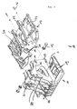
- the supporting steel structure 10 comprises a first element 11 and a second element 12, which are each designed as a welded construction and connected to each other via bolts 13 and screws 16.
- the first element 11 of the turntable 4 is arranged for rotatable articulation of the upper carriage 3 on the undercarriage 1. Furthermore, the first element 11 on the articulation areas 21 and 22 for connection to the stem 5.
- the first element of a bottom plate 19, on which the turntable 4 is arranged, and side cheeks 20 is constructed. On the side cheeks 20, which are perpendicular to the bottom plate 19 and extend along the longitudinal axis of the upper carriage, while the articulation 21 for articulation of a Stem member 22 and provided for the articulation of hydraulic cylinders for moving the stem.
- the first element 11 carries the driver's cab 6.
- the second, rearwardly disposed element 12 of the supporting steel construction carries the ballast and the power pack of the implement.
- the second element 12 also has a bottom construction 23 and two side cheeks 24.
- connecting areas 25 are provided on the side cheeks 24 at the rear, on which the ballast is placed.
- the side cheeks 24 also extend in the longitudinal direction of the upper carriage, wherein they are aligned in the mounted position of the first and the second element with the side cheeks of the first element.
- the common Verbolzungsachse runs horizontally.
- bolt receivers 14 are provided on the side cheeks 20 of the first element 14 and on the side cheeks 24 of the second member 12 bolt receptacles 15 which are bolted together via bolts 13.
- the bolts thus fix the second element along a common Verbolzungsachse against the first element.
- the bolt connections are designed detachable.
- the first and the second element z. B. to transport the excavator to be dismantled.
- the bolts 13 are thereby mounted from the inside, as the left side of the side walls of the oil tank and right side of the side cheeks of the fuel tank is mounted.
- stop areas 17 and 18 are provided on the first and on the second element, in which the second element is supported on the first element.
- the static forces acting perpendicular to the bolting axis are recorded.
- the static moments exerted by the dead weight of the second element 12, the ballast and the power pack are introduced into the first element 11 via the abutment regions 17 and 18 perpendicular to the bolt axis acting as the axis of rotation.
- the bolt connections are essentially on train, the stop areas essentially loaded on pressure.
- the stop areas are arranged for this purpose below the Verbolzungsachse in the bottom region of the side walls.
- screws 16 are provided, which connect the first and the second element.
- the glands are arranged in the stop areas 17 and 18 on the first and on the second element.
- the Verschraubungsachsen lie in each case in planes which are perpendicular to the Verbolzungsachse. As in FIG. 3 becomes clear, the Verschraubungsachsen run substantially horizontally in the bottom region of the first and the second element.
- the screw connections are arranged in the bottom region of the side cheeks 20 and 24 on the first and on the second element.
- the glands serve to secure the first and second element against movement about the Verbolzungsachse.
- the balance of power on the superstructure are in particular from FIG. 6 can be seen:
- the first element 10 is arranged on the turntable 4 on its bottom plate about the vertical axis of rotation 30 rotatably mounted on the undercarriage. All forces from the superstructure are transferred to the undercarriage via the turntable of the first element.
- 21 and 22 of the excavator handle is articulated on the first element via the articulation areas.
- the second element carries the power pack, not shown, and the ballast 26, which is fastened in the rear connection region 25 by means of screws on the second element.
- the center of gravity of the ballast is shown at 27, the center of gravity of the power pack, not shown with 28.
- the screws 16 are further provided, which prevent movement of the second element in a plane perpendicular to the Verbolzungsachse 13.
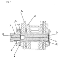
- FIGS. 7 to 9 an embodiment of a correspondingly designed bolt connection according to the invention is shown.
- 42 CRMO4 and a bolt diameter of 140 mm are used as the material.
- the bolt is constructed in two parts and consists of a Sp Schwarzbuchse 32 with conical inner diameter and a plunger 31 with conical outer diameter.
- the expansion sleeve has a cylindrical outer diameter and is slotted in the longitudinal direction to improve their function.
- the expansion sleeve 32 in this case has a collar 41, via which it rests on the side surface of the bolt receptacle.
- the bearing surface between the collar 41 and bolt receptacle is dimensioned so that the force which acts on the expansion bushing during pressing in, is transferred in compliance with the permissible surface pressure.
- doubling 45 are provided on the side cheeks 20 in the area of the bolt receptacles. These are welded to the sheets of the side cheeks 20.
- the plunger 31 For pressing of bolt and bolt receiving the plunger 31 is pressed via a press-in screw 33 in the expansion sleeve 32.
- the press-in screw 33 is screwed into a holder 34, which is screwed to the side wall 20 of the first element.
- a locking nut 37 is provided, via which the press-in screw is held in position.
- the press-in screw (M120) is approximately as large as the outer diameter of the bolt connection with 140 mm. As a result, the surface pressure is kept small at the end face of the plunger 31 and on the press-in screw. Second, this results in a short lever arm between the thread 35 of the holder and its connection to the side wall 20, so that the bending moment in the holder remains low.
- the holder 34 is designed as a disk, in which the thread 35 is arranged centrally for screwing the press-fit screw 33 and which is screwed to the side cheek 20 via a plurality of screws 36, which are arranged in a circle around the thread 35.
- the ten screws 36 for connecting the holder 34 with the side wall 20 form a circle of holes with a diameter of 235 mm.
- the press-in screw 33 is first unscrewed from the holder 34 to release the bolt connection, so that the end face of the expansion piston is accessible.
- the expansion piston 31 has a thread 37 on its end face, into which a peel-off screw 42 can be screwed.
- the peel-off screw (in the exemplary embodiment M64) has a smaller diameter than the press-in screw and can thus be screwed through the holder 34 into the thread 37.
- a washer 43 is used, via which the head of the peel-off screw 42 rests on the holder 34.
Landscapes
- Engineering & Computer Science (AREA)
- Mining & Mineral Resources (AREA)
- Civil Engineering (AREA)
- General Engineering & Computer Science (AREA)
- Structural Engineering (AREA)
- Connection Of Plates (AREA)
- Component Parts Of Construction Machinery (AREA)
Applications Claiming Priority (2)
| Application Number | Priority Date | Filing Date | Title |
|---|---|---|---|
| DE202008013896U DE202008013896U1 (de) | 2008-10-17 | 2008-10-17 | Verfahrbares Arbeitsgerät |
| EP09012099.9A EP2177670B1 (fr) | 2008-10-17 | 2009-09-23 | Châssis porteur pour un appareil de travail mobile |
Related Parent Applications (3)
| Application Number | Title | Priority Date | Filing Date |
|---|---|---|---|
| EP09012099.9A Division EP2177670B1 (fr) | 2008-10-17 | 2009-09-23 | Châssis porteur pour un appareil de travail mobile |
| EP09012099.9A Division-Into EP2177670B1 (fr) | 2008-10-17 | 2009-09-23 | Châssis porteur pour un appareil de travail mobile |
| EP09012099.9 Division | 2009-09-23 |
Publications (2)
| Publication Number | Publication Date |
|---|---|
| EP2573280A2 true EP2573280A2 (fr) | 2013-03-27 |
| EP2573280A3 EP2573280A3 (fr) | 2014-05-14 |
Family
ID=41211703
Family Applications (2)
| Application Number | Title | Priority Date | Filing Date |
|---|---|---|---|
| EP12008385.2A Withdrawn EP2573280A3 (fr) | 2008-10-17 | 2009-09-23 | Structure en acier supportant la superstructure d'un engin de travail |
| EP09012099.9A Not-in-force EP2177670B1 (fr) | 2008-10-17 | 2009-09-23 | Châssis porteur pour un appareil de travail mobile |
Family Applications After (1)
| Application Number | Title | Priority Date | Filing Date |
|---|---|---|---|
| EP09012099.9A Not-in-force EP2177670B1 (fr) | 2008-10-17 | 2009-09-23 | Châssis porteur pour un appareil de travail mobile |
Country Status (3)
| Country | Link |
|---|---|
| US (1) | US8177017B2 (fr) |
| EP (2) | EP2573280A3 (fr) |
| DE (2) | DE202008013896U1 (fr) |
Families Citing this family (11)
| Publication number | Priority date | Publication date | Assignee | Title |
|---|---|---|---|---|
| WO2008147410A1 (fr) * | 2007-05-26 | 2008-12-04 | Koss Michael J | Structure de renforcement de rattrapage pour interface d'élévateur de cabines rops |
| US8631595B2 (en) * | 2011-06-22 | 2014-01-21 | Jason Wayne McDonald | Excavating apparatus with swivel mount employing swivel adapter with gear bearings having gears with divergent thickness |
| US8621770B1 (en) * | 2012-06-22 | 2014-01-07 | Jason Wayne McDonald | Excavating apparatus employing swivel adapter with gear bearings having gears with divergent thickness |
| DE102011105522A1 (de) | 2011-06-22 | 2012-12-27 | Thomas Sauer | Bagger |
| DE102011109080A1 (de) * | 2011-07-27 | 2013-01-31 | Liebherr-Hydraulikbagger Gmbh | Drehbühnenelement für eine Baumaschine |
| WO2013131132A1 (fr) | 2012-03-06 | 2013-09-12 | Technofast Industries Pty Ltd | Boulons de couplage à ajustement radial de grande capacité |
| USD686252S1 (en) * | 2012-05-10 | 2013-07-16 | Hitachi Construction Machinery Co., Ltd. | Frame for a construction machine |
| GB2531765B (en) * | 2014-10-29 | 2017-09-13 | Bamford Excavators Ltd | An undercarriage for a working machine |
| US20170107689A1 (en) * | 2015-10-14 | 2017-04-20 | Caterpillar Inc. | Support structure for frame of a machine |
| USD921057S1 (en) * | 2019-06-26 | 2021-06-01 | J.C. Bamford Excavators Limited | Excavator |
| CN113846719B (zh) * | 2021-09-26 | 2023-09-01 | 江苏徐工工程机械研究院有限公司 | 回转平台、工程车辆及其组装方法 |
Family Cites Families (52)
| Publication number | Priority date | Publication date | Assignee | Title |
|---|---|---|---|---|
| FR808480A (fr) * | 1935-10-26 | 1937-02-08 | Boulon perfectionné | |
| US3271058A (en) * | 1963-05-22 | 1966-09-06 | Anderson Greenwood & Co | Tapered fastener |
| FR2238017B1 (fr) * | 1973-07-16 | 1976-04-30 | Poclain Sa | |
| US4055262A (en) * | 1976-02-02 | 1977-10-25 | Clark Equipment Company | Loader main frame for skid steer loader |
| US4151920A (en) * | 1977-07-11 | 1979-05-01 | Caterpillar Tractor Co. | Vehicle main frame |
| US4096957A (en) * | 1977-07-18 | 1978-06-27 | Caterpillar Tractor Co. | Pivot pin assembly |
| JPS5985037A (ja) * | 1982-11-01 | 1984-05-16 | Hikoma Seisakusho Kk | 掘削機の旋回機構 |
| US4640641A (en) * | 1984-07-25 | 1987-02-03 | Teledyne Continental Motors | Piston pin construction and method for forming same |
| DE3432194A1 (de) * | 1984-09-01 | 1986-03-13 | Jürgen Dipl.-Ing. 4300 Essen Mallepree | Spannstift |
| JPS621939A (ja) * | 1985-06-27 | 1987-01-07 | Hitachi Constr Mach Co Ltd | 掘削機の上部旋回体の取付け構造 |
| JP2659291B2 (ja) * | 1991-06-28 | 1997-09-30 | 株式会社クボタ | 作業車の走行装置 |
| US5320443A (en) * | 1992-01-28 | 1994-06-14 | Commercial Intertech Corp. | Connecting pin |
| JP2812416B2 (ja) * | 1993-01-13 | 1998-10-22 | ヤンマーディーゼル株式会社 | 旋回作業車 |
| JP2834383B2 (ja) * | 1993-04-09 | 1998-12-09 | 株式会社クボタ | バックホウの旋回台構造 |
| CN1069373C (zh) * | 1996-06-04 | 2001-08-08 | 日立建机株式会社 | 带驾驶室的工程机械 |
| FI108157B (fi) * | 1996-08-13 | 2001-11-30 | Waertsilae Finland Oy | Kytkentämenetelmä ja laite |
| US6170588B1 (en) * | 1997-06-03 | 2001-01-09 | Hitachi Construction Machinery Co., Ltd. | Revolving construction machine |
| DE29718592U1 (de) * | 1997-10-20 | 1998-02-19 | D + H Mechatronic, Dingfelder + Kern GmbH, 22949 Ammersbek | Verbindungs- oder Sicherungsbolzen |
| US6098739A (en) * | 1998-06-05 | 2000-08-08 | Caterpillar S.A.R.L. | Main frame assembly |
| JP3056716B2 (ja) * | 1998-07-23 | 2000-06-26 | 株式会社小松製作所 | 建設機械のメインフレーム |
| DE19906168C1 (de) * | 1999-02-08 | 2000-09-21 | Atec Weiss Gmbh & Co Kg | Konusschraubverbindung für Lamellenpaket-Wellenkupplungen |
| US6322104B1 (en) * | 1999-03-02 | 2001-11-27 | Clark Equipment Company | Excavator frame and method of assembly |
| US6089343A (en) * | 1999-05-21 | 2000-07-18 | Deere & Company | Vehicle frame |
| KR100382823B1 (ko) * | 1999-09-01 | 2003-05-09 | 가부시끼 가이샤 구보다 | 백호 |
| JP4265723B2 (ja) * | 2000-08-15 | 2009-05-20 | 株式会社小松製作所 | 履帯式建設機械車輌のフレーム構造 |
| JP2002097667A (ja) * | 2000-09-27 | 2002-04-02 | Komatsu Ltd | 建設機械の旋回フレーム構造およびその組立方法 |
| CN1201055C (zh) * | 2000-12-01 | 2005-05-11 | 日立建机株式会社 | 建筑机械 |
| US7156200B2 (en) * | 2001-04-19 | 2007-01-02 | Caterpillar S.A.R.L. | Main frame for a tracked skid steer loader machine |
| DE10201673B4 (de) * | 2002-01-17 | 2008-04-17 | Liebherr-Hydraulikbagger Gmbh | Materialumschlaggerät |
| US6886277B2 (en) * | 2002-02-15 | 2005-05-03 | Kubota Corporation | Small swivel type working vehicle |
| US7523804B2 (en) * | 2002-03-26 | 2009-04-28 | Kobelco Construction Machinery Co., Ltd. | Small swing type shovel |
| US6772544B2 (en) * | 2002-03-28 | 2004-08-10 | Kubota Corporation | Wheeled work vehicle |
| US7374208B2 (en) * | 2003-03-18 | 2008-05-20 | Kobelco Construction Machinery Co., Ltd. | Working machine |
| GB2418661B (en) * | 2003-07-01 | 2007-01-17 | Komatsu Mfg Co Ltd | Construction machine and projecting member thereof` |
| WO2005035341A1 (fr) * | 2003-10-14 | 2005-04-21 | Hitachi Construction Machinery Co., Ltd. | Engin de construction |
| DE112005000728T5 (de) * | 2004-03-31 | 2007-03-22 | Kobelco Cranes Co., Ltd. | Kran und Verfahren zum Zusammenbauen des Krans |
| DE102004032868A1 (de) | 2004-07-07 | 2006-02-09 | Liebherr-Hydraulikbagger Gmbh | Bagger und Maschine zum Materialumschlag |
| GB2419117B (en) * | 2004-10-14 | 2008-03-05 | Jcb Compact Products Ltd | Working machine |
| KR100693978B1 (ko) * | 2004-11-19 | 2007-03-12 | 가부시끼 가이샤 구보다 | 선회 작업기 |
| JP2006200313A (ja) * | 2005-01-24 | 2006-08-03 | Hitachi Constr Mach Co Ltd | 建設機械 |
| US7204546B2 (en) * | 2005-03-11 | 2007-04-17 | Saf-T-Cab, Inc. | Vehicle cab slide pivot |
| JP4928087B2 (ja) * | 2005-03-14 | 2012-05-09 | ヤンマー株式会社 | 作業車両のフレーム構造 |
| JP2006298355A (ja) * | 2005-03-24 | 2006-11-02 | Hitachi Constr Mach Co Ltd | 作業機械 |
| JP4828156B2 (ja) * | 2005-05-13 | 2011-11-30 | キャタピラー エス エー アール エル | 旋回型作業機械 |
| GB2427666B (en) * | 2005-06-25 | 2007-05-16 | Northern Hydraulic Cylinder En | A pin |
| JP4667142B2 (ja) * | 2005-07-05 | 2011-04-06 | ヤンマー株式会社 | 旋回作業車 |
| JP4167675B2 (ja) * | 2005-07-05 | 2008-10-15 | ヤンマー株式会社 | 旋回作業車 |
| DE102005052014B4 (de) * | 2005-11-02 | 2008-03-20 | Airbus Deutschland Gmbh | Kegelbolzenverbindung sowie Verwendung einer Kegelbolzenverbindung |
| GB0525689D0 (en) * | 2005-12-16 | 2006-01-25 | Airbus Uk Ltd | A fastener assembly |
| ES1062476Y (es) * | 2006-03-24 | 2006-09-16 | Larrea Guillermo Petri | Perno a cortadura y traccion de diametro variable |
| JP4185118B2 (ja) * | 2006-06-27 | 2008-11-26 | 日立建機株式会社 | 建設機械 |
| JP4941089B2 (ja) * | 2007-05-15 | 2012-05-30 | コベルコ建機株式会社 | 上部旋回体及びこれを備えた建設機械 |
-
2008
- 2008-10-17 DE DE202008013896U patent/DE202008013896U1/de not_active Expired - Lifetime
-
2009
- 2009-09-01 DE DE102009039918A patent/DE102009039918A1/de not_active Withdrawn
- 2009-09-23 EP EP12008385.2A patent/EP2573280A3/fr not_active Withdrawn
- 2009-09-23 EP EP09012099.9A patent/EP2177670B1/fr not_active Not-in-force
- 2009-10-15 US US12/580,168 patent/US8177017B2/en active Active
Non-Patent Citations (1)
| Title |
|---|
| None |
Also Published As
| Publication number | Publication date |
|---|---|
| US20100096211A1 (en) | 2010-04-22 |
| EP2573280A3 (fr) | 2014-05-14 |
| DE102009039918A1 (de) | 2010-04-22 |
| EP2177670B1 (fr) | 2014-03-12 |
| DE202008013896U1 (de) | 2010-03-11 |
| EP2177670A1 (fr) | 2010-04-21 |
| US8177017B2 (en) | 2012-05-15 |
Similar Documents
| Publication | Publication Date | Title |
|---|---|---|
| EP2177670B1 (fr) | Châssis porteur pour un appareil de travail mobile | |
| DE102007017812A1 (de) | Baugerät, Mäkler und Verfahren zur Montage des Mäklers am Baugerät | |
| EP0819041A1 (fr) | Robot industriel avec equilibrage des masses | |
| DE202021106818U1 (de) | Mobilkran mit einer Gegengewichtsvorrichtung | |
| EP2864548B2 (fr) | Dispositif pour compaction d'un sol | |
| EP2620548B1 (fr) | Engin avec structure de cabine à oscillations découplées et dispositif d'attelage | |
| EP2981495A1 (fr) | Machine de travail mobile, en particulier pompe à béton automotrice et procédé de fabrication | |
| EP2288770B1 (fr) | Dispositif pour démolir des constructions | |
| DE112009001680T5 (de) | Tandemradanordnung | |
| DE69910443T2 (de) | Lenkeinrichtung für gelenk- kettenfahrzeuge | |
| DE69820508T2 (de) | Mechanisch angetriebene Gleiskette | |
| DE102006007468A1 (de) | Rohrverlegerunterrahmen und damit ausgestattete Arbeitsmaschine | |
| EP2772589B1 (fr) | Engin | |
| DE10143716B4 (de) | Mobiles Arbeitsgerät mit Stützträgern und Verfahren zum Betrieb dieses Arbeitsgeräts | |
| DE2528177C2 (de) | Aufreißer an einem Erdbaufahrzeug | |
| DE102018114314B4 (de) | Winkelstück und Hebevorrichtung | |
| DE1708871B1 (de) | Fahrbarer Betonmischer | |
| EP2003030A2 (fr) | Dispositif d'appui de véhicule utilitaire | |
| DE102007021059A1 (de) | Flexibles Gelenk | |
| EP1369299A1 (fr) | Hayon élévateur avec plate-forme assiste par un ressort | |
| EP1120376B1 (fr) | Machine de pose de conduites | |
| DE69225707T2 (de) | Schwenkbarer verriegelungsmechanismus für baugeräte mit rotierbarem oberbau | |
| DE69705290T2 (de) | Getriebegehäuse für einen Schlepper | |
| EP3947982B1 (fr) | Unité de tige de piston, vérin hydraulique et mât articulé | |
| DE102014010279B4 (de) | Vorrichtung zum Überspannen einer Drehbühne einer mobilen Arbeitsmaschine zur Erhöhung der Tragfähigkeit und Haltbarkeit |
Legal Events
| Date | Code | Title | Description |
|---|---|---|---|
| PUAI | Public reference made under article 153(3) epc to a published international application that has entered the european phase |
Free format text: ORIGINAL CODE: 0009012 |
|
| 17P | Request for examination filed |
Effective date: 20121217 |
|
| AC | Divisional application: reference to earlier application |
Ref document number: 2177670 Country of ref document: EP Kind code of ref document: P |
|
| AK | Designated contracting states |
Kind code of ref document: A2 Designated state(s): AT BE BG CH CY CZ DE DK EE ES FI FR GB GR HR HU IE IS IT LI LT LU LV MC MK MT NL NO PL PT RO SE SI SK SM TR |
|
| RIC1 | Information provided on ipc code assigned before grant |
Ipc: E02F 9/08 20060101AFI20140128BHEP Ipc: E02F 9/00 20060101ALI20140128BHEP |
|
| PUAL | Search report despatched |
Free format text: ORIGINAL CODE: 0009013 |
|
| AK | Designated contracting states |
Kind code of ref document: A3 Designated state(s): AT BE BG CH CY CZ DE DK EE ES FI FR GB GR HR HU IE IS IT LI LT LU LV MC MK MT NL NO PL PT RO SE SI SK SM TR |
|
| RIC1 | Information provided on ipc code assigned before grant |
Ipc: E02F 9/08 20060101AFI20140410BHEP Ipc: E02F 9/00 20060101ALI20140410BHEP |
|
| STAA | Information on the status of an ep patent application or granted ep patent |
Free format text: STATUS: THE APPLICATION IS DEEMED TO BE WITHDRAWN |
|
| 18D | Application deemed to be withdrawn |
Effective date: 20141115 |