EP2573357A1 - Soupape de décharge à turbocompresseur - Google Patents
Soupape de décharge à turbocompresseur Download PDFInfo
- Publication number
- EP2573357A1 EP2573357A1 EP12183139A EP12183139A EP2573357A1 EP 2573357 A1 EP2573357 A1 EP 2573357A1 EP 12183139 A EP12183139 A EP 12183139A EP 12183139 A EP12183139 A EP 12183139A EP 2573357 A1 EP2573357 A1 EP 2573357A1
- Authority
- EP
- European Patent Office
- Prior art keywords
- lever
- flap
- valve body
- turbocharger
- flap device
- Prior art date
- Legal status (The legal status is an assumption and is not a legal conclusion. Google has not performed a legal analysis and makes no representation as to the accuracy of the status listed.)
- Withdrawn
Links
Images
Classifications
-
- F—MECHANICAL ENGINEERING; LIGHTING; HEATING; WEAPONS; BLASTING
- F02—COMBUSTION ENGINES; HOT-GAS OR COMBUSTION-PRODUCT ENGINE PLANTS
- F02B—INTERNAL-COMBUSTION PISTON ENGINES; COMBUSTION ENGINES IN GENERAL
- F02B37/00—Engines characterised by provision of pumps driven at least for part of the time by exhaust
- F02B37/12—Control of the pumps
- F02B37/18—Control of the pumps by bypassing exhaust from the inlet to the outlet of turbine or to the atmosphere
- F02B37/183—Arrangements of bypass valves or actuators therefor
- F02B37/186—Arrangements of actuators or linkage for bypass valves
-
- F—MECHANICAL ENGINEERING; LIGHTING; HEATING; WEAPONS; BLASTING
- F02—COMBUSTION ENGINES; HOT-GAS OR COMBUSTION-PRODUCT ENGINE PLANTS
- F02B—INTERNAL-COMBUSTION PISTON ENGINES; COMBUSTION ENGINES IN GENERAL
- F02B37/00—Engines characterised by provision of pumps driven at least for part of the time by exhaust
- F02B37/12—Control of the pumps
- F02B37/18—Control of the pumps by bypassing exhaust from the inlet to the outlet of turbine or to the atmosphere
- F02B37/183—Arrangements of bypass valves or actuators therefor
-
- F—MECHANICAL ENGINEERING; LIGHTING; HEATING; WEAPONS; BLASTING
- F02—COMBUSTION ENGINES; HOT-GAS OR COMBUSTION-PRODUCT ENGINE PLANTS
- F02B—INTERNAL-COMBUSTION PISTON ENGINES; COMBUSTION ENGINES IN GENERAL
- F02B37/00—Engines characterised by provision of pumps driven at least for part of the time by exhaust
- F02B37/02—Gas passages between engine outlet and pump drive, e.g. reservoirs
- F02B37/025—Multiple scrolls or multiple gas passages guiding the gas to the pump drive
-
- F—MECHANICAL ENGINEERING; LIGHTING; HEATING; WEAPONS; BLASTING
- F05—INDEXING SCHEMES RELATING TO ENGINES OR PUMPS IN VARIOUS SUBCLASSES OF CLASSES F01-F04
- F05D—INDEXING SCHEME FOR ASPECTS RELATING TO NON-POSITIVE-DISPLACEMENT MACHINES OR ENGINES, GAS-TURBINES OR JET-PROPULSION PLANTS
- F05D2220/00—Application
- F05D2220/40—Application in turbochargers
-
- F—MECHANICAL ENGINEERING; LIGHTING; HEATING; WEAPONS; BLASTING
- F05—INDEXING SCHEMES RELATING TO ENGINES OR PUMPS IN VARIOUS SUBCLASSES OF CLASSES F01-F04
- F05D—INDEXING SCHEME FOR ASPECTS RELATING TO NON-POSITIVE-DISPLACEMENT MACHINES OR ENGINES, GAS-TURBINES OR JET-PROPULSION PLANTS
- F05D2260/00—Function
- F05D2260/50—Kinematic linkage, i.e. transmission of position
- F05D2260/56—Kinematic linkage, i.e. transmission of position using cams or eccentrics
-
- F—MECHANICAL ENGINEERING; LIGHTING; HEATING; WEAPONS; BLASTING
- F05—INDEXING SCHEMES RELATING TO ENGINES OR PUMPS IN VARIOUS SUBCLASSES OF CLASSES F01-F04
- F05D—INDEXING SCHEME FOR ASPECTS RELATING TO NON-POSITIVE-DISPLACEMENT MACHINES OR ENGINES, GAS-TURBINES OR JET-PROPULSION PLANTS
- F05D2260/00—Function
- F05D2260/60—Fluid transfer
- F05D2260/606—Bypassing the fluid
-
- Y—GENERAL TAGGING OF NEW TECHNOLOGICAL DEVELOPMENTS; GENERAL TAGGING OF CROSS-SECTIONAL TECHNOLOGIES SPANNING OVER SEVERAL SECTIONS OF THE IPC; TECHNICAL SUBJECTS COVERED BY FORMER USPC CROSS-REFERENCE ART COLLECTIONS [XRACs] AND DIGESTS
- Y02—TECHNOLOGIES OR APPLICATIONS FOR MITIGATION OR ADAPTATION AGAINST CLIMATE CHANGE
- Y02T—CLIMATE CHANGE MITIGATION TECHNOLOGIES RELATED TO TRANSPORTATION
- Y02T10/00—Road transport of goods or passengers
- Y02T10/10—Internal combustion engine [ICE] based vehicles
- Y02T10/12—Improving ICE efficiencies
Definitions
- the invention relates to a flap device for a turbocharger wastegate valve.
- a boost pressure control is needed.
- This control can be achieved by means of a wastegate valve (also called by-pass valve or pressure relief valve) in the exhaust gas flow.
- the wastegate valve is controlled by a flap coupled to an encoder on the compressor side of the turbocharger. With the flap closed, all of the exhaust gas flows through the turbine of the turbocharger, driving the turbine shaft at full load. When a predetermined charge pressure is exceeded, the wastegate valve is opened, whereby a large proportion of the exhaust gas is passed to the turbine of the turbocharger over directly into the exhaust, which prevents a further increase in turbine speed.
- the flaps known wastegate valves consist of several relatively movable components.
- a tolerance compensation is achieved when closing the flap, since the flap can align automatically and jamming or oblique seat of the flap on the opposite bypass opening of the turbine housing (Abgaseinströmö réelle) is avoided.
- the relative mobility of the flap components is mandatory according to the prevailing theory for the desired sealing between the sealing surface of the flap and the bypass opening.
- the object of the invention is to provide a robust flap device for a wastegate valve of a turbocharger.
- the flapper device for a turbocharger wastegate valve comprises a lever, which is provided for connection to a mechanical control device, and a valve body with a flap portion, which is provided for covering a bypass opening.
- a lever which is provided for connection to a mechanical control device
- a valve body with a flap portion which is provided for covering a bypass opening.
- at least the lever and the valve body are integrally formed. This means that the lever and the valve body (and possibly also other parts) of the flap device are not subsequently assembled, but are made of a workpiece.
- the invention is based on the surprising finding that with a one-piece flap device against the prevailing doctrine, a sufficient seal can be achieved. It has been shown that with known flap devices, the relatively movable components tend to oscillate under certain circumstances (flutter), which not only has a negative effect on the wear, but obviously also has a negative effect on the tightness. Although it can not align itself, just in such cases, a one-piece flap device is superior because it can not be so easily excited to vibrate as a solid item. In assessing the overall performance of the valve device, this factor outweighs the lack of tolerance compensation.
- the susceptibility to wear decreases significantly, whereby the life of the flap device can be significantly increased. In addition, rattling noises are excluded.
- the one-piece Manufacture of the flap device is also cheaper to implement than the complex assembly of several items and allows a lower overall weight of the flap device.
- a preferred material for the lever and valve body is a corrosion resistant nickel base alloy (Inconel).
- the lever and the valve body may also be formed from an austenitic stainless steel, in particular HK 30th
- the invention also provides a wastegate valve for a turbocharger, in particular for a twin-scroll loader, with a flap device according to the invention.
- the invention provides a turbocharger, in particular a twin-scroll supercharger, with a wastegate valve according to the invention.
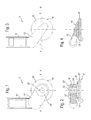
- a multi-part flap device 10 'for a wastegate valve according to the prior art is shown.
- the flap device 10 ' comprises a lever 12', which is coupled to a mechanical control device in the form of a linkage not shown here.
- the linkage is in turn connected to a donor on the compressor side of the associated turbocharger.
- the lever 12 ' is mounted in a bushing 14', wherein a radial clearance of the bearing ensures limited mobility of the lever 12 'in the bushing 14'.
- the lever 12 At its free end, the lever 12 'on a bore 16', in which a valve body 18 'is also mounted with a radial clearance.
- a valve body 18 ' At its free end, the lever 12 'on a bore 16', in which a valve body 18 'is also mounted with a radial clearance.
- the valve body 18 'in the bore 16' to a limited extent movable.
- the valve body 18 ' is divided into a plurality of axial sections with different diameters. On one side of the bore 16 'of the valve body 18' terminates with a wide flap portion 20 'from, on the other side with a compared to the bore 16' narrower end portion 22 '.
- the flap portion 20 'and the end portion 22' are interconnected by a central portion 24 'located in the bore 16' and a bearing portion 26 'disposed between the lever 12' and the flap portion 20 '.
- the end portion 22 ' is received in the opening of an annular disc 28' and fixedly connected thereto, for example by electron beam welding. Since the bearing portion 26 'and the annular disc 28' have a larger diameter than the bore 16 'of the lever 12', the valve body 18 'is loosely but captively mounted on the lever 12'.
- the flapper 10 ' may be transferred from the closed position to the open position and vice versa by the transmitter and linkage 14'.
- the sealing surface 30 'formed on the free end face of the flap section 20' covers an opposite bypass opening of the turbine housing of the turbocharger.
- the play between the lever 12 'and the sleeve 14' and the clearance between the valve body 18 'and the edge of the bore 16' for optimum alignment of the sealing surface 30 'with respect to the bypass opening.
- the flapper 10 ' releases the bypass opening.
- FIGS. 3 and 4 a flap device 10 according to the invention is shown. Those parts which correspond to those of the previously described flap device 10 'are provided with the same reference numerals, but without the addition, and reference is made to the above explanations in this respect.
- the flap device 10 is formed in one piece.
- "One-part" is to be understood here as one-piece, d. H. made of the same workpiece, without any subsequent parts were assembled.
- lever 12 and the valve body 18 with the flap portion 20 is a unit.
- a movable mounting of the valve body 18 by means of a bore in the lever 12 or an additional annular disc is not provided.
- a certain mobility of the one-piece flap device 10 is possible by the play provided bearing of the lever 12 in the socket 14.
- lever 12 and valve body 18 are corrosion-resistant nickel-based alloys or austenitic stainless steel.
- the operation of the flap device 10 according to the invention is the same as that of the flap device 10 'of the prior art with the exceptions that the valve body 18 can not automatically align relative to the lever 12 and that the mobility of the lever 12 in the socket 14 due to one-piece design of the flap device 10 is somewhat limited.
- the flap device shown is particularly suitable for twin-scroll turbocharger, which differ from other superchargers by the different design of the exhaust manifold and the two-part exhaust gas inlet of the turbine housing.
Landscapes
- Engineering & Computer Science (AREA)
- Chemical & Material Sciences (AREA)
- Combustion & Propulsion (AREA)
- Mechanical Engineering (AREA)
- General Engineering & Computer Science (AREA)
- Supercharger (AREA)
Applications Claiming Priority (1)
| Application Number | Priority Date | Filing Date | Title |
|---|---|---|---|
| DE102011083369A DE102011083369A1 (de) | 2011-09-26 | 2011-09-26 | Klappenvorrichtung für ein Turbolader-Wastegateventil |
Publications (1)
| Publication Number | Publication Date |
|---|---|
| EP2573357A1 true EP2573357A1 (fr) | 2013-03-27 |
Family
ID=46758680
Family Applications (1)
| Application Number | Title | Priority Date | Filing Date |
|---|---|---|---|
| EP12183139A Withdrawn EP2573357A1 (fr) | 2011-09-26 | 2012-09-05 | Soupape de décharge à turbocompresseur |
Country Status (2)
| Country | Link |
|---|---|
| EP (1) | EP2573357A1 (fr) |
| DE (1) | DE102011083369A1 (fr) |
Cited By (4)
| Publication number | Priority date | Publication date | Assignee | Title |
|---|---|---|---|---|
| DE102013222920A1 (de) | 2013-11-11 | 2015-05-13 | Schaeffler Technologies AG & Co. KG | Heissgasventil für Turbinengehäuse eines Turboladers einer Brennkraftmaschine und Verfahren zur Montage |
| EP2915977A1 (fr) * | 2014-03-06 | 2015-09-09 | Honeywell International Inc. | Soupape de décharge de turbine |
| US9556786B2 (en) | 2012-09-13 | 2017-01-31 | Honeywell International Inc. | Turbine wastegate |
| EP3660278A1 (fr) * | 2018-11-29 | 2020-06-03 | Toyota Jidosha Kabushiki Kaisha | Turbocompresseur |
Families Citing this family (1)
| Publication number | Priority date | Publication date | Assignee | Title |
|---|---|---|---|---|
| DE102011077766A1 (de) * | 2011-06-17 | 2012-12-20 | Elringklinger Ag | Betätigungseinrichtung für ein Abgasstrom-Steuerelement eines Abgasturboladers |
Citations (5)
| Publication number | Priority date | Publication date | Assignee | Title |
|---|---|---|---|---|
| US4245953A (en) * | 1979-01-18 | 1981-01-20 | General Motors Corporation | Engine turbocharger with cartridge wastegate valve |
| JPH0643227U (ja) * | 1992-06-01 | 1994-06-07 | 愛三工業株式会社 | ターボチャージャ用ウェイストゲートバルブ |
| JP2011058426A (ja) * | 2009-09-10 | 2011-03-24 | Ihi Corp | 調整バルブ及び過給装置 |
| US20110175025A1 (en) * | 2008-09-25 | 2011-07-21 | Borgwarner Inc. | Turbocharger and subassembly for bypass control in the turbine casing therefor |
| EP2444626A1 (fr) * | 2010-03-01 | 2012-04-25 | Mitsubishi Heavy Industries, Ltd. | Dispositif soupape de décharge |
Family Cites Families (7)
| Publication number | Priority date | Publication date | Assignee | Title |
|---|---|---|---|---|
| DE102007013612A1 (de) * | 2007-03-22 | 2008-09-25 | Deutz Power Systems Gmbh | Brennkraftmaschine mit einem Abgasturbolader |
| JP2009024584A (ja) * | 2007-07-19 | 2009-02-05 | Toyota Motor Corp | 内燃機関の排気通路制御装置 |
| DE102008014680A1 (de) * | 2008-03-18 | 2010-09-23 | Continental Automotive Gmbh | Leitgitteranordnung eines Abgasturboladers, Abgasturbolader und Verfahren zur Herstellung einer Leitgitteranordnung |
| EP2313636A4 (fr) * | 2008-07-10 | 2015-10-07 | Actuant Corp | Actionneur de soupape de recirculation de gaz d'échappement |
| DE102008032928A1 (de) * | 2008-07-12 | 2010-01-14 | Bosch Mahle Turbo Systems Gmbh & Co. Kg | Abgasturbolader für ein Kraftfahrzeug |
| DE102008032929A1 (de) * | 2008-07-12 | 2010-01-14 | Bosch Mahle Turbo Systems Gmbh & Co. Kg | Abgasturbolader für ein Kraftfahrzeug |
| DE102009015899B4 (de) * | 2009-04-01 | 2021-03-04 | Bayerische Motoren Werke Aktiengesellschaft | Verschlussklappe für einen Abgasturbolader |
-
2011
- 2011-09-26 DE DE102011083369A patent/DE102011083369A1/de active Pending
-
2012
- 2012-09-05 EP EP12183139A patent/EP2573357A1/fr not_active Withdrawn
Patent Citations (5)
| Publication number | Priority date | Publication date | Assignee | Title |
|---|---|---|---|---|
| US4245953A (en) * | 1979-01-18 | 1981-01-20 | General Motors Corporation | Engine turbocharger with cartridge wastegate valve |
| JPH0643227U (ja) * | 1992-06-01 | 1994-06-07 | 愛三工業株式会社 | ターボチャージャ用ウェイストゲートバルブ |
| US20110175025A1 (en) * | 2008-09-25 | 2011-07-21 | Borgwarner Inc. | Turbocharger and subassembly for bypass control in the turbine casing therefor |
| JP2011058426A (ja) * | 2009-09-10 | 2011-03-24 | Ihi Corp | 調整バルブ及び過給装置 |
| EP2444626A1 (fr) * | 2010-03-01 | 2012-04-25 | Mitsubishi Heavy Industries, Ltd. | Dispositif soupape de décharge |
Cited By (6)
| Publication number | Priority date | Publication date | Assignee | Title |
|---|---|---|---|---|
| US9556786B2 (en) | 2012-09-13 | 2017-01-31 | Honeywell International Inc. | Turbine wastegate |
| DE102013222920A1 (de) | 2013-11-11 | 2015-05-13 | Schaeffler Technologies AG & Co. KG | Heissgasventil für Turbinengehäuse eines Turboladers einer Brennkraftmaschine und Verfahren zur Montage |
| WO2015067254A1 (fr) | 2013-11-11 | 2015-05-14 | Schaeffler Technologies AG & Co. KG | Soupape de gaz chauds pour le carter de turbine d'un turbocompresseur de moteur à combustion interne et procédé de montage correspondant |
| EP2915977A1 (fr) * | 2014-03-06 | 2015-09-09 | Honeywell International Inc. | Soupape de décharge de turbine |
| EP3536929A1 (fr) * | 2014-03-06 | 2019-09-11 | Honeywell International Inc. | Soupape de décharge de turbine |
| EP3660278A1 (fr) * | 2018-11-29 | 2020-06-03 | Toyota Jidosha Kabushiki Kaisha | Turbocompresseur |
Also Published As
| Publication number | Publication date |
|---|---|
| DE102011083369A1 (de) | 2013-03-28 |
Similar Documents
| Publication | Publication Date | Title |
|---|---|---|
| EP2092176B1 (fr) | Turbocompresseur | |
| EP2715089B1 (fr) | Turbocompresseur à gaz d'échappement comportant une vanne à décharge/à boisseau sphérique pourvue d'un bras de manivelle à détente des contraintes | |
| DE112013002306T5 (de) | Abgasturbolader | |
| DE102010007600A1 (de) | Betätigungseinrichtung für ein Ventil, insbesondere ein Waste-Gate eines Abgasturboladers | |
| EP1290314B1 (fr) | Turbocompresseur pour moteur a combustion interne | |
| DE102009030482A1 (de) | Abgasbaugruppe | |
| DE112014001968T5 (de) | Ventilmechanismus mit variabler Durchflussrate und Turbolader | |
| EP2573357A1 (fr) | Soupape de décharge à turbocompresseur | |
| DE102009048125A1 (de) | Wastegate-Anordnung für eine Turbine, Turbine für einen Abgasturbolader, Abgasturbolader, Kraftfahrzeug und Verfahren zum Betreiben eines Abgasturboladers | |
| DE102017221403A1 (de) | Ventilklappeneinrichtung für ein Bypass-Ventil eines Abgasturboladers sowie Abgasturbolader | |
| DE102016208158A1 (de) | Turbine für einen Abgasturbolader mit zweiflutigem Turbinengehäuse und Ventil-Anordnung zur Flutenverbindung und Wastegate-Steuerung | |
| DE102006021185B4 (de) | Verschlussklappe für einen Abgasturbolader | |
| WO2018036757A1 (fr) | Matériau ferreux pour bagues de paliers résistant à haute température, bague pour palier réalisée dans ce matériau et turbocompresseur doté d'une telle bague de palier | |
| DE102016208160B4 (de) | Turbine für einen Abgasturbolader mit zweiflutigem Turbinengehäuse und einer Ventil-Anordnung mit verbesserter Abströmung | |
| WO2013182619A1 (fr) | Carter de turbine pour turbocompresseur à gaz d'echappement | |
| DE112012002572T5 (de) | Mehrstufiges Turboladersystem | |
| EP3199778A1 (fr) | Turbosoufflante de gaz d'échappement pour un moteur à combustion interne | |
| DE102012001236A1 (de) | Leiteinrichtung für eine Turbine eines Abgasturboladers | |
| DE102010020340A1 (de) | Regelklappe | |
| DE202009015888U1 (de) | Dichtanordnung einer Welle | |
| DE102008061687A1 (de) | Abgasturbolader für ein Kraftfahrzeug | |
| DE102016214840A1 (de) | Bypass-Ventil mit Ventilsitzschürze für einen Abgasturbolader und Abgasturbolader mit einem solchen Bypass-Ventil | |
| DE102007028346A1 (de) | Aufladeeinrichtung für Brennkraftmaschinen | |
| EP3867505A1 (fr) | Turbine à gaz d'échappement d'un turbocompresseur comprenant un dispositif de soupape wastegate étanchéifié, ainsi que turbocompresseur | |
| DE102010021973A1 (de) | Ladeeinrichtung |
Legal Events
| Date | Code | Title | Description |
|---|---|---|---|
| PUAI | Public reference made under article 153(3) epc to a published international application that has entered the european phase |
Free format text: ORIGINAL CODE: 0009012 |
|
| AK | Designated contracting states |
Kind code of ref document: A1 Designated state(s): AL AT BE BG CH CY CZ DE DK EE ES FI FR GB GR HR HU IE IS IT LI LT LU LV MC MK MT NL NO PL PT RO RS SE SI SK SM TR |
|
| AX | Request for extension of the european patent |
Extension state: BA ME |
|
| STAA | Information on the status of an ep patent application or granted ep patent |
Free format text: STATUS: THE APPLICATION IS DEEMED TO BE WITHDRAWN |
|
| 18D | Application deemed to be withdrawn |
Effective date: 20130928 |