EP2573467A2 - Chambre de combustion de turbine et procédé de régulation de température et d'amortissement d'une partie d'une chambre de combustion - Google Patents
Chambre de combustion de turbine et procédé de régulation de température et d'amortissement d'une partie d'une chambre de combustion Download PDFInfo
- Publication number
- EP2573467A2 EP2573467A2 EP12184186A EP12184186A EP2573467A2 EP 2573467 A2 EP2573467 A2 EP 2573467A2 EP 12184186 A EP12184186 A EP 12184186A EP 12184186 A EP12184186 A EP 12184186A EP 2573467 A2 EP2573467 A2 EP 2573467A2
- Authority
- EP
- European Patent Office
- Prior art keywords
- combustor
- temperature control
- wall
- holes
- outer member
- Prior art date
- Legal status (The legal status is an assumption and is not a legal conclusion. Google has not performed a legal analysis and makes no representation as to the accuracy of the status listed.)
- Withdrawn
Links
- 238000013016 damping Methods 0.000 title claims abstract description 30
- 238000000034 method Methods 0.000 title claims description 11
- 239000012530 fluid Substances 0.000 claims description 51
- 238000002485 combustion reaction Methods 0.000 claims description 20
- 239000007789 gas Substances 0.000 description 27
- 239000000446 fuel Substances 0.000 description 15
- 238000001816 cooling Methods 0.000 description 7
- 239000012809 cooling fluid Substances 0.000 description 4
- 238000004891 communication Methods 0.000 description 3
- 239000000203 mixture Substances 0.000 description 3
- 238000010586 diagram Methods 0.000 description 2
- VNWKTOKETHGBQD-UHFFFAOYSA-N methane Chemical compound C VNWKTOKETHGBQD-UHFFFAOYSA-N 0.000 description 2
- UFHFLCQGNIYNRP-UHFFFAOYSA-N Hydrogen Chemical compound [H][H] UFHFLCQGNIYNRP-UHFFFAOYSA-N 0.000 description 1
- 230000004075 alteration Effects 0.000 description 1
- 238000006243 chemical reaction Methods 0.000 description 1
- 238000010790 dilution Methods 0.000 description 1
- 239000012895 dilution Substances 0.000 description 1
- 239000001257 hydrogen Substances 0.000 description 1
- 229910052739 hydrogen Inorganic materials 0.000 description 1
- 239000007788 liquid Substances 0.000 description 1
- 238000004519 manufacturing process Methods 0.000 description 1
- 230000007246 mechanism Effects 0.000 description 1
- 239000003345 natural gas Substances 0.000 description 1
- 230000010355 oscillation Effects 0.000 description 1
- 230000009257 reactivity Effects 0.000 description 1
- 239000000126 substance Substances 0.000 description 1
- 238000006467 substitution reaction Methods 0.000 description 1
- 230000007704 transition Effects 0.000 description 1
Images


Classifications
-
- F—MECHANICAL ENGINEERING; LIGHTING; HEATING; WEAPONS; BLASTING
- F23—COMBUSTION APPARATUS; COMBUSTION PROCESSES
- F23R—GENERATING COMBUSTION PRODUCTS OF HIGH PRESSURE OR HIGH VELOCITY, e.g. GAS-TURBINE COMBUSTION CHAMBERS
- F23R3/00—Continuous combustion chambers using liquid or gaseous fuel
- F23R3/02—Continuous combustion chambers using liquid or gaseous fuel characterised by the air-flow or gas-flow configuration
- F23R3/04—Air inlet arrangements
- F23R3/06—Arrangement of apertures along the flame tube
-
- F—MECHANICAL ENGINEERING; LIGHTING; HEATING; WEAPONS; BLASTING
- F23—COMBUSTION APPARATUS; COMBUSTION PROCESSES
- F23R—GENERATING COMBUSTION PRODUCTS OF HIGH PRESSURE OR HIGH VELOCITY, e.g. GAS-TURBINE COMBUSTION CHAMBERS
- F23R2900/00—Special features of, or arrangements for continuous combustion chambers; Combustion processes therefor
- F23R2900/00014—Reducing thermo-acoustic vibrations by passive means, e.g. by Helmholtz resonators
-
- F—MECHANICAL ENGINEERING; LIGHTING; HEATING; WEAPONS; BLASTING
- F23—COMBUSTION APPARATUS; COMBUSTION PROCESSES
- F23R—GENERATING COMBUSTION PRODUCTS OF HIGH PRESSURE OR HIGH VELOCITY, e.g. GAS-TURBINE COMBUSTION CHAMBERS
- F23R2900/00—Special features of, or arrangements for continuous combustion chambers; Combustion processes therefor
- F23R2900/03042—Film cooled combustion chamber walls or domes
-
- F—MECHANICAL ENGINEERING; LIGHTING; HEATING; WEAPONS; BLASTING
- F23—COMBUSTION APPARATUS; COMBUSTION PROCESSES
- F23R—GENERATING COMBUSTION PRODUCTS OF HIGH PRESSURE OR HIGH VELOCITY, e.g. GAS-TURBINE COMBUSTION CHAMBERS
- F23R2900/00—Special features of, or arrangements for continuous combustion chambers; Combustion processes therefor
- F23R2900/03044—Impingement cooled combustion chamber walls or subassemblies
Definitions
- the subject matter disclosed herein relates to turbines. More particularly, the subject matter relates to combustion dynamics control and temperature control of a turbine.
- a combustor converts chemical energy of a fuel or an air-fuel mixture into thermal energy.
- the thermal energy is conveyed by a fluid, often air from a compressor, to a turbine where the thermal energy is converted to mechanical energy.
- a fluid often air from a compressor
- the thermal energy is converted to mechanical energy.
- factors influence the efficiency of the conversion of thermal energy to mechanical energy. The factors may include blade passing frequencies, fuel supply fluctuations, fuel type and reactivity, combustor head-on volume, fuel nozzle design, air-fuel profiles, flame shape, air-fuel mixing, flame holding, combustion temperature, turbine component design, hot-gas-path temperature dilution, and exhaust temperature.
- high combustion temperatures in selected locations in the turbine engine may enable improved combustion efficiency and power production.
- high temperatures may shorten the life and increase wear and tear of certain components.
- effective operation of turbine engines may also involve managing combustion dynamics, i.e., dynamic instabilities in operation.
- Dynamics are often caused by fluctuations in such conditions as the temperature of exhaust gases and oscillating pressure levels within regions of the turbine, such as within the combustor.
- High dynamics can limit hardware life and operability of an engine, due to such factors as mechanical and thermal fatigue.
- a turbine combustor includes an outer member coupled to a wall of the combustor, wherein there is at least one damping hole formed in outer member.
- the turbine combustor further includes at least one temperature control hole formed in the wall wherein the at least one temperature control hole is formed at an angle with respect to a line perpendicular to a hot gas path in the combustor.
- a method for temperature control and damping a portion of a combustor includes flowing a treatment fluid through at least one damping hole in an outer member coupled to a wall of the combustor, wherein the outer member forms a resonator cavity that receives the treatment fluid.
- the method further includes flowing the treatment fluid from the resonator cavity through at least one temperature control hole formed in the wall, wherein the at least one temperature control hole is formed at an angle with respect to a line perpendicular to a hot gas path in the combustor.
- FIG. 1 is a schematic diagram of an embodiment of a gas turbine system 100.
- the system 100 includes a compressor 102, a combustor 104, a turbine 106, a shaft 108 and a fuel nozzle 110.
- the system 100 may include a plurality of compressors 102, combustors 104, turbines 106, shafts 108 and fuel nozzles 110.
- the compressor 102 and turbine 106 are coupled by the shaft 108.
- the shaft 108 may be a single shaft or a plurality of shaft segments coupled together to form shaft 108.
- the combustor 104 uses liquid and/or gas fuel, such as natural gas or a hydrogen rich synthetic gas, to run the turbine engine.
- fuel nozzles 110 are in fluid communication with a fuel supply and pressurized air from the compressor 102.
- the fuel nozzles 110 create an air-fuel mix, and discharge the air-fuel mix into the combustor 104, thereby causing a combustion that creates a hot pressurized exhaust gas.
- the combustor 104 directs the hot pressurized exhaust gas through a transition piece into a turbine nozzle (or "stage one nozzle"), causing turbine 106 rotation as the gas exits the nozzle or vane and gets directed to the turbine bucket or blade.
- the rotation of turbine 106 causes the shaft 108 to rotate, thereby compressing the air as it flows into the compressor 102.
- hot gas flow through portions of the turbine such as the combustor 104, causes wear and thermal fatigue of turbine parts, due to non-uniform temperatures. Controlling the temperature of parts of the combustor 104 can reduce wear and enable higher combustion temperatures, thereby improving performance.
- oscillations and vibration due to pressure changes and combustion i.e. combustion dynamics, can also wear portions of the combustor 104.
- Combustion dynamics may be controlled and reduced by selected mechanisms, such as resonators, to reduce wear and improve life of the combustor 104. Controlling combustion dynamics of and temperatures of the combustor 104 are discussed in detail below with reference to FIGS. 2-3 .
- FIG. 2 is a detailed sectional view of a portion of an exemplary combustor 200.
- the combustor 200 includes an outer member 202 coupled to an outer side of a wall 204.
- One or more holes 206 or passages are formed in the outer member 202 to enable fluid flow 208 to a cavity 210 formed within the outer member 202 and wall 204.
- the outer member 202 and holes 206 (also referred to as "damping holes”) form a resonator apparatus coupled to the wall 204 to control and reduce combustion dynamics.
- a cooling fluid flow 212 also referred to as "treatment fluid”
- treatment fluid such as an air flow
- the wall 204 also includes one or more holes 214 or passages for directing fluid flow 216 inside the combustor toward a hot gas path 218 or flow.
- the holes 214 (also referred to as “cooling holes” or “temperature control holes”) may be located outside or within the outer member 202, wherein the holes within the outer member 202 are in fluid communication with the cavity 210.
- the holes 214 are formed at an angle 220 with respect to a line perpendicular to the hot gas path 218.
- the holes enable effusion temperature control and cooling of the combustor 200 and wall 204 via the fluid flow 216.
- the angle 220 ranges from about 10 to about 80 degrees. In other embodiments, the angle 220 ranges from about 15 to about 60 degrees.
- the angle 220 ranges from about 15 to about 45 degrees. It should be understood that examples may include discussion of cooling the combustor 20, however, embodiments may also include temperature control or treatment of the combustor, wherein the temperature of the combustor is maintained at a temperature or is allowed to rise at a selected rate.
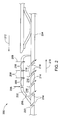
- FIG. 3 is a detailed sectional view of a portion of an exemplary combustor 300.
- the combustor 300 includes an outer member 302 coupled to an outside portion of a wall 304.
- One or more holes 306 or passages are formed in the outer member 302 to enable fluid flow 308 to a cavity 310 formed within the outer member 302 and wall 304.
- the outer member 302 and holes 306 (also referred to as "damping holes”) form a resonator apparatus coupled to the combustor 300 to control and reduce combustion dynamics.
- a portion of a cooling fluid flow 312 also referred to as "treatment fluid”
- treatment fluid forms the fluid flow 308 that is directed into the cavity 310.
- the wall 304 also includes one or more holes 314 or passages (also referred to as “cooling holes” or “temperature control holes”) configured to direct fluid flow 316 inside the combustor 300 and along one or more members 318 formed on an inner side 320 of the wall 304.
- the members 318 are configured to direct the fluid flow 316 along the inner side 320, to enable cooling of the wall 304.
- the members 318 may be any suitable shape to cause fluid flow 316 in a desired direction, such as airfoils, blades, ridges, wings or any other suitable geometry. As depicted, the members 318 are laterally offset or staggered, but may be arranged in any suitable fashion to control temperature of portions of the combustor 300 via fluid flow 316.
- the members 318 create a flow component for fluid flow 316 that is substantially parallel to a hot gas path 324 and an axis 325 of the combustor 300.
- the holes 314 may be located outside or within the outer member 302, wherein the holes within the outer member 302 are in fluid communication with the cavity 310.
- exemplary holes 314 may include one or more holes proximate members 318 while additional holes 314 may be positioned substantially away or removed from members 318.
- the holes 314 are formed at an angle 322 with respect to a line perpendicular to the hot gas path 324, thus enabling cooling of at lease a portion of the combustor 300 and wall 304 via the fluid flow 316.
- the angle 322 may range from about 10 to about 80 degrees. In other embodiments, the angle 322 may range from about 15 to about 60 degrees. In yet other embodiments, the angle 322 may range from about 15 to about 45 degrees.
- the holes 206, 214, 306, 314 may be any suitable geometry and orientation configured to direct fluid flow to portions of the combustors 200, 300. Exemplary geometries of the cross-sectional flow area of the holes may be circular, rectangular, oval, ellipses, rectangles or other suitable shapes.
- temperatures of the combustors 200, 300 inside the walls 204, 304 range from about 2500 to about 3500 degrees F.
- the flow of the cooling fluid 212, 312 to fluid flows 208, 308 and 214, 314 inside the combustors 200, 300 (and along with members 318 for combustor 300) provide improved temperature control and/or cooling to reduce wear for the turbine components.
- the arrangement of the outer member 202, 302 and holes 206, 306 act as a resonating apparatus to provide damping and control combustion dynamics.
- the outer members 202, 302 are coupled to walls 204, 302 to form Hemholtz resonators configured to provide damping and control combustion dynamics.
- the resonators are tuned to combustion dynamics frequency and are thereby configured to cause damping of combustion dynamics at the selected frequency.
- the depicted arrangement improves turbine reliability and performance by improving temperature control while controlling combustion dynamics for the exemplary combustors 200, 300.
- the depicted portions of the combustors 200, 300 may be any portion of the combustor, including but not limited to the liner or cap region.
Landscapes
- Engineering & Computer Science (AREA)
- Chemical & Material Sciences (AREA)
- Combustion & Propulsion (AREA)
- Mechanical Engineering (AREA)
- General Engineering & Computer Science (AREA)
- Turbine Rotor Nozzle Sealing (AREA)
Priority Applications (1)
| Application Number | Priority Date | Filing Date | Title |
|---|---|---|---|
| PT141841866T PT2844030E (pt) | 2012-09-13 | 2012-11-21 | Tecido de aquecimento |
Applications Claiming Priority (1)
| Application Number | Priority Date | Filing Date | Title |
|---|---|---|---|
| US13/240,290 US20130074471A1 (en) | 2011-09-22 | 2011-09-22 | Turbine combustor and method for temperature control and damping a portion of a combustor |
Publications (1)
| Publication Number | Publication Date |
|---|---|
| EP2573467A2 true EP2573467A2 (fr) | 2013-03-27 |
Family
ID=46888321
Family Applications (1)
| Application Number | Title | Priority Date | Filing Date |
|---|---|---|---|
| EP12184186A Withdrawn EP2573467A2 (fr) | 2011-09-22 | 2012-09-13 | Chambre de combustion de turbine et procédé de régulation de température et d'amortissement d'une partie d'une chambre de combustion |
Country Status (3)
| Country | Link |
|---|---|
| US (1) | US20130074471A1 (fr) |
| EP (1) | EP2573467A2 (fr) |
| CN (1) | CN103075744A (fr) |
Cited By (3)
| Publication number | Priority date | Publication date | Assignee | Title |
|---|---|---|---|---|
| EP2865947A1 (fr) * | 2013-10-28 | 2015-04-29 | Alstom Technology Ltd | Amortisseur pour turbines à gaz |
| EP3309457A1 (fr) * | 2016-10-13 | 2018-04-18 | General Electric Company | Système d'atténuation de la dynamique de combustion |
| US10451283B2 (en) | 2015-01-28 | 2019-10-22 | Ansaldo Energia Switzerland AG | Sequential combustor arrangement with a mixer |
Families Citing this family (12)
| Publication number | Priority date | Publication date | Assignee | Title |
|---|---|---|---|---|
| US10100737B2 (en) * | 2013-05-16 | 2018-10-16 | Siemens Energy, Inc. | Impingement cooling arrangement having a snap-in plate |
| EP2860451A1 (fr) * | 2013-10-11 | 2015-04-15 | Alstom Technology Ltd | Chambre de combustion d'une turbine à gaz avec amortissement acoustique amélioré |
| US9625158B2 (en) | 2014-02-18 | 2017-04-18 | Dresser-Rand Company | Gas turbine combustion acoustic damping system |
| EP3026346A1 (fr) * | 2014-11-25 | 2016-06-01 | Alstom Technology Ltd | Chemise de chambre de combustion |
| US20160245094A1 (en) * | 2015-02-24 | 2016-08-25 | General Electric Company | Engine component |
| US10513984B2 (en) | 2015-08-25 | 2019-12-24 | General Electric Company | System for suppressing acoustic noise within a gas turbine combustor |
| US20170226929A1 (en) * | 2016-02-09 | 2017-08-10 | General Electric Company | Fuel injector covers and methods of fabricating same |
| US20170234226A1 (en) * | 2016-02-16 | 2017-08-17 | Russell B. Jones | Cooled Combustor Case with Over-Pressurized Cooling Air |
| US10197275B2 (en) | 2016-05-03 | 2019-02-05 | General Electric Company | High frequency acoustic damper for combustor liners |
| JP2021063464A (ja) * | 2019-10-15 | 2021-04-22 | 三菱パワー株式会社 | ガスタービン燃焼器 |
| JP7393262B2 (ja) * | 2020-03-23 | 2023-12-06 | 三菱重工業株式会社 | 燃焼器、及びこれを備えるガスタービン |
| DE102020213836A1 (de) * | 2020-11-04 | 2022-05-05 | Siemens Energy Global GmbH & Co. KG | Resonatorring, Verfahren und Brennkorb |
Family Cites Families (19)
| Publication number | Priority date | Publication date | Assignee | Title |
|---|---|---|---|---|
| GB2017827B (en) * | 1978-04-04 | 1983-02-02 | Gen Electric | Combustor liner cooling |
| US4622821A (en) * | 1985-01-07 | 1986-11-18 | United Technologies Corporation | Combustion liner for a gas turbine engine |
| US4773593A (en) * | 1987-05-04 | 1988-09-27 | United Technologies Corporation | Coolable thin metal sheet |
| JP3590666B2 (ja) * | 1995-03-30 | 2004-11-17 | 株式会社東芝 | ガスタービン燃焼器 |
| FR2752916B1 (fr) * | 1996-09-05 | 1998-10-02 | Snecma | Chemise de protection thermique pour chambre de combustion de turboreacteur |
| US6250082B1 (en) * | 1999-12-03 | 2001-06-26 | General Electric Company | Combustor rear facing step hot side contour method and apparatus |
| US6530221B1 (en) * | 2000-09-21 | 2003-03-11 | Siemens Westinghouse Power Corporation | Modular resonators for suppressing combustion instabilities in gas turbine power plants |
| US6543233B2 (en) * | 2001-02-09 | 2003-04-08 | General Electric Company | Slot cooled combustor liner |
| US6546733B2 (en) * | 2001-06-28 | 2003-04-15 | General Electric Company | Methods and systems for cooling gas turbine engine combustors |
| US7086232B2 (en) * | 2002-04-29 | 2006-08-08 | General Electric Company | Multihole patch for combustor liner of a gas turbine engine |
| US7146815B2 (en) * | 2003-07-31 | 2006-12-12 | United Technologies Corporation | Combustor |
| US6868675B1 (en) * | 2004-01-09 | 2005-03-22 | Honeywell International Inc. | Apparatus and method for controlling combustor liner carbon formation |
| US7219498B2 (en) * | 2004-09-10 | 2007-05-22 | Honeywell International, Inc. | Waffled impingement effusion method |
| EP1832812A3 (fr) * | 2006-03-10 | 2012-01-04 | Rolls-Royce Deutschland Ltd & Co KG | Paroi de chambre de combustion de turbine à gaz avec amortissement des vibrations de la chambre de combustion |
| US8051663B2 (en) * | 2007-11-09 | 2011-11-08 | United Technologies Corp. | Gas turbine engine systems involving cooling of combustion section liners |
| US9587832B2 (en) * | 2008-10-01 | 2017-03-07 | United Technologies Corporation | Structures with adaptive cooling |
| US20100170257A1 (en) * | 2009-01-08 | 2010-07-08 | General Electric Company | Cooling a one-piece can combustor and related method |
| US8307657B2 (en) * | 2009-03-10 | 2012-11-13 | General Electric Company | Combustor liner cooling system |
| US20110185739A1 (en) * | 2010-01-29 | 2011-08-04 | Honeywell International Inc. | Gas turbine combustors with dual walled liners |
-
2011
- 2011-09-22 US US13/240,290 patent/US20130074471A1/en not_active Abandoned
-
2012
- 2012-09-13 EP EP12184186A patent/EP2573467A2/fr not_active Withdrawn
- 2012-09-21 CN CN2012103569941A patent/CN103075744A/zh active Pending
Non-Patent Citations (1)
| Title |
|---|
| None |
Cited By (4)
| Publication number | Priority date | Publication date | Assignee | Title |
|---|---|---|---|---|
| EP2865947A1 (fr) * | 2013-10-28 | 2015-04-29 | Alstom Technology Ltd | Amortisseur pour turbines à gaz |
| US10036327B2 (en) | 2013-10-28 | 2018-07-31 | Ansaldo Energia Switzerland AG | Damper with bent neck for gas turbine |
| US10451283B2 (en) | 2015-01-28 | 2019-10-22 | Ansaldo Energia Switzerland AG | Sequential combustor arrangement with a mixer |
| EP3309457A1 (fr) * | 2016-10-13 | 2018-04-18 | General Electric Company | Système d'atténuation de la dynamique de combustion |
Also Published As
| Publication number | Publication date |
|---|---|
| US20130074471A1 (en) | 2013-03-28 |
| CN103075744A (zh) | 2013-05-01 |
Similar Documents
| Publication | Publication Date | Title |
|---|---|---|
| EP2573467A2 (fr) | Chambre de combustion de turbine et procédé de régulation de température et d'amortissement d'une partie d'une chambre de combustion | |
| US9217373B2 (en) | Fuel nozzle for reducing modal coupling of combustion dynamics | |
| CN101220965B (zh) | 翼片、套筒及用于组装燃烧器组件的方法 | |
| US8904798B2 (en) | Combustor | |
| US10094568B2 (en) | Combustor dynamics mitigation | |
| EP1852614B1 (fr) | Tuyère propulsive à faible bruit pour éjecteur | |
| US9528701B2 (en) | System for tuning a combustor of a gas turbine | |
| EP3290805B1 (fr) | Ensemble de buse de combustible comportant un résonateur | |
| US20130000312A1 (en) | Turbomachine combustor assembly including a vortex modification system | |
| WO2013044197A2 (fr) | Section de résonateur de chambre de combustion avec un revêtement de barrière thermique interne et son procédé de fabrication | |
| US20150167979A1 (en) | First stage nozzle or transition nozzle configured to promote mixing of respective combustion streams downstream thereof before entry into a first stage bucket of a turbine | |
| US20150159878A1 (en) | Combustion system for a gas turbine engine | |
| KR20080090314A (ko) | 연소기 다이나믹스 감쇄 시스템 | |
| US11371699B2 (en) | Integrated front panel for a burner | |
| EP2629018A2 (fr) | Système à injection tardive pauvre | |
| EP2647799B1 (fr) | Chambre de combustion tubulaire de turbine à gaz avec l'extrémité de tête ovale ou elliptique | |
| US20140311156A1 (en) | Combustor cap for damping low frequency dynamics | |
| EP2669476A2 (fr) | Ensemble de refroidissement pour une aube d'un système de turbine et procédé de refroidissement associé | |
| US20140318140A1 (en) | Premixer assembly and mechanism for altering natural frequency of a gas turbine combustor | |
| CN205001072U (zh) | 燃料供应系统和燃气涡轮系统 | |
| US11280270B2 (en) | Igniter assembly for a gas turbine combustor | |
| US20150315981A1 (en) | Fuel supply system | |
| CN104654357A (zh) | 燃气轮机燃烧室 | |
| EP3184736A1 (fr) | Caisson de transfert de chaleur en biais | |
| US11428409B2 (en) | Combustor and gas turbine including the same |
Legal Events
| Date | Code | Title | Description |
|---|---|---|---|
| PUAI | Public reference made under article 153(3) epc to a published international application that has entered the european phase |
Free format text: ORIGINAL CODE: 0009012 |
|
| AK | Designated contracting states |
Kind code of ref document: A2 Designated state(s): AL AT BE BG CH CY CZ DE DK EE ES FI FR GB GR HR HU IE IS IT LI LT LU LV MC MK MT NL NO PL PT RO RS SE SI SK SM TR |
|
| AX | Request for extension of the european patent |
Extension state: BA ME |
|
| STAA | Information on the status of an ep patent application or granted ep patent |
Free format text: STATUS: THE APPLICATION IS DEEMED TO BE WITHDRAWN |
|
| 18D | Application deemed to be withdrawn |
Effective date: 20160401 |